
Part of the John Deere Repair Manuals.
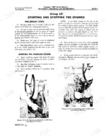
Wrenching on a John Deere 720 diesel? This 342-page John Deere 720 Service Manual PDF (OEM #SM2020) walks you through the two-cylinder diesel, the pony cranking engine, Powr-Trol hydraulics, transmission, and final drives from teardown to reassembly. Inside: factory wiring diagrams for the generator, voltage regulator, and lighting harness, a full troubleshooting section, and page after page of tune-up and adjustment procedures for both engines. Check compression at 450 to 490 psi, set the rockshaft relief valve between 1300 and 1400 psi, and verify cranking motor brush tension at 24 to 28 ounces before you button it up. These old two-bangers don't forgive guesswork. Bookmarked by section, this PDF opens on any laptop, tablet, or phone; carry it right out to the tractor and get to work.
What's Inside This John Deere 720 Manual
| System | Pages | Key Topics |
|---|---|---|
| Description, Operation and Specifications | 11-22 | Tractor Description (Pulls Five 14-Inch Plow Bottoms, General-Purpose and Standard Styles, Six Forward Speeds and One Reverse), Serial Number Locations for Tractor, Cranking Engine, Distributor, Powr-Trol Valve Housing and Remote Cylinder, General Specifications |
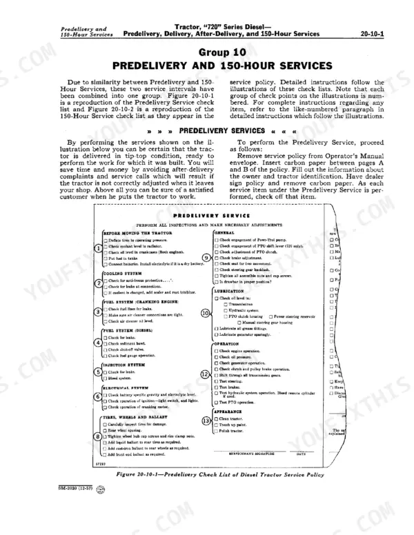
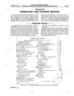
| Predelivery, Delivery, After-Delivery and 150-Hour Services | 23-48 | Dealer Service Policy Check Lists: Predelivery Inspection, Delivery Inspection and the 150-Hour Inspection, As Issued in the Booklet Accompanying Each New Tractor |
| Tune-Up and Adjustment | 49-76 | Purpose of Tune-Up and Adjustment, Diesel Engine Tune-Up, Cranking Engine Tune-Up and Clutch Adjustment |
| Diesel Engine | 77-112 | Description, Cylinder Head, Valves, And Related Parts, Pistons, Connecting Rods and Cylinder Block, Crankshaft, Flywheel |
| Cranking Engine and Accessories | 113-154 | Cranking Engine, Valve Mechanism, Governor, Camshaft, And Related Parts, Pistons and Connecting Rods, Crankshaft and Bushings, Cranking Engine Cooling System |
| Governor and Speed-Control Linkage | 155-170 | Governor Shaft Assembly, Governor Case and Fan Shaft Assembly, Fan Drive Assembly |
| Electrical System | 171-174 | Generator and Voltage Regulator, Battery, Lights, And Wiring Harness |
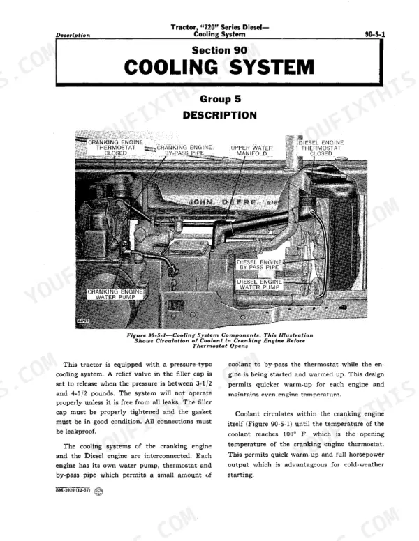
| Cooling System | 175-184 | Description, Radiator and Thermostat, Diesel Engine Water Pump |
| Diesel Engine Lubrication System | 185-196 | Oil Pump and Drive Assembly, Oil Filter, Pressure Regulator and Oil Lines |
| Fuel System | 197-212 | Description and Operation, Fuel Tank and Sediment Bowl, Fuel Transfer Pump, Fuel Filters, Fuel Injection Pumps, Injection Nozzles, Air Cleaner and Pipes |
| Pulley, Clutch and Pulley Brake | 213-224 | Pulley and Clutch, Pulley Brake, Clutch Parts, And Reduction Gear Cover |
| Transmission | 225-246 | Description and Operation, Shifter Mechanism, Transmission Shafts and Gears |
| Powershaft | 247-270 | Powershaft Driving and Shifting Mechanism, Powershaft Clutch, Clutch Drum and Oil Pump |
| Differential and Final Drive | 271-284 | Group 05 Differential (Spider with Three Bevel Pinions, Differential Ring Gear Driven Off the Transmission Countershaft, Differential Shaft on Tapered Roller Bearings, End Play Set by Shims), Final Drive Gears on the Rear Axles |
| Float-Ride Seat | 285-288 | Float-Ride Seat and Seat Cushions |
| Brakes | 289-292 | Brake Shoe Assembly, Brake Drum, Brake Shaft, Pedal, Cam, Adjusting Screw |
| Wheels and Tires | 293-308 | Front Wheels, Rear Wheels, Tires and Wheel Weights |
| Steering Mechanism and Front Axle | 309-332 | Steering Mechanism, Roll-O-Matic, Wide Adjustable-Tread Front Axle |
| Custom Powr-Trol | 333-342 | General Description and Pump, Remote Cylinder Valve Housings and Rockshaft Housing |
Quick Reference Specifications
| Specification | Value | Page |
|---|---|---|
| rockshaft relief valve opening pressure | 1300 to 1400 psi | p. 40 |
| single valve housing relief valve opening pressure | 1230 to 1300 psi | p. 43 |
| Compression pressure | 450 to 490 pounds per square inch | p. 53 |
| Cranking motor Brush Tension | 24-28 oz. | p. 143 |
| AB 4744 R Starts to Open | 160° F | p. 180 |
| AB 4744 R Fully Open | 182° F | p. 180 |
| Sediment bowl service interval | 10 hours of operation | p. 203 |
| 1st Stage Filter service interval | 450 hours of operation | p. 203 |
| Air cleaner service interval | 30 hours of operation | p. 211 |
| Fuel transfer pump pressure | 12 to 24 psi | p. 201 |
| Injection nozzle opening pressure | 2400 psi | p. 209 |
| Diesel Engine Rated Load Speed | 1125 rpm | p. 12 |
John Deere 720 Common Problems This Manual Covers
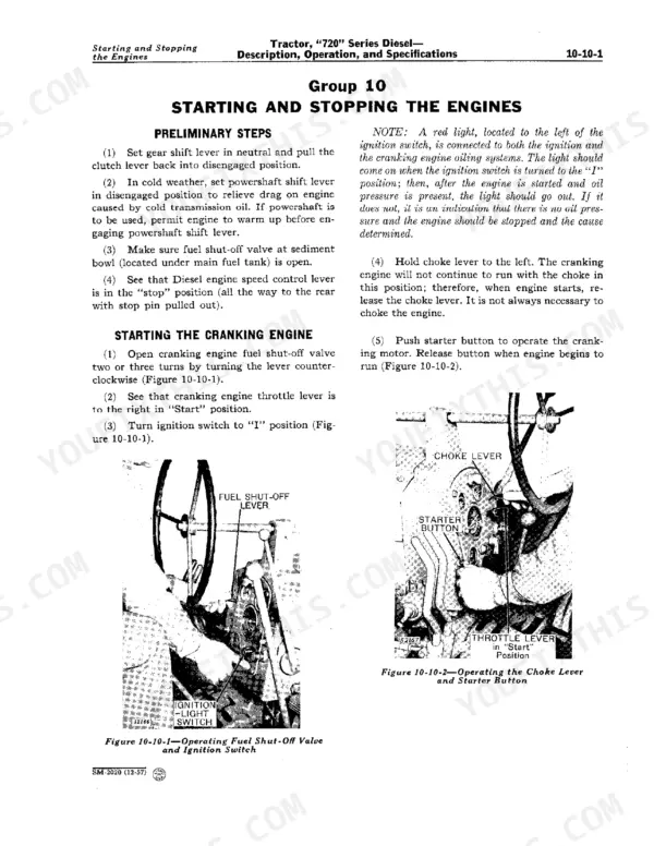
John Deere 720 diesel hard to start, needs bleeding after sitting, dies right after firing
Check the sediment bowl first; drain and clean it every 10 hours of operation. Test transfer pump output, which should hold 12 to 24 psi per the spec on page 201. If pressure is low, remove the pump and inspect the diaphragm, then bleed the filters and lines until fuel runs clear at the injection pump.
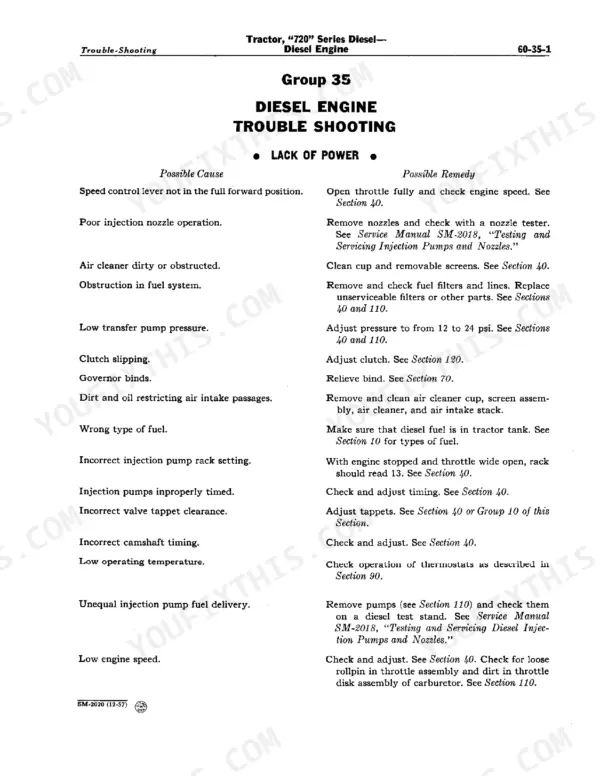
Manual Section: Fuel System p. 201Diesel loses power under load, black smoke, engine bogs down pulling a plow
Service the air cleaner; under normal conditions it needs attention every 30 hours of operation, sooner in dusty fieldwork. Replace the first stage fuel filter at 450 hours or when contaminated. Run a compression test next; a healthy engine reads 450 to 490 psi per the tune-up specs on page 53, and anything lower points to valve or ring work.
Manual Section: Diesel Engine Trouble Shooting p. 107Engine overheats after an hour of field work, coolant pushing out the overflow
Check coolant level and blow chaff out of the radiator core before condemning parts. Test the thermostats in heated water: the AB 4744 R unit starts opening at 160 degrees F and should be fully open at 182 degrees F, per the chart on page 180. Replace any thermostat that sticks closed, then pressure test the system for leaks.
Manual Section: Cooling System p. 180Powr-Trol hydraulics slow and weak, remote cylinder creeps down under load
Verify hydraulic oil level and inspect the pump and valve housing fittings for leaks. Test relief valve opening pressure with a gauge: a single valve housing should open at 1230 to 1300 psi per page 43, and the rockshaft relief valve at 1300 to 1400 psi. Low readings mean a weak relief valve spring or internal pump leakage.
Manual Section: Custom Powr-Trol p. 333Pony motor cranks the diesel slowly, starter drags and barely turns over when cold
Inspect the cranking motor brushes and commutator for oil film and wear. Check brush spring tension against the 24-28 oz. specification on page 143 and replace weak springs. Clean and tighten battery cable connections, then load test the battery. If the motor still drags, pull it and check the bushings and armature for scoring.
Manual Section: Cranking Engine and Accessories p. 143Frequently Asked Questions
What are the torque specifications for a John Deere 720 cylinder head?
The cylinder head nuts on the John Deere 720 must be tightened to 275 foot-pounds. It is important to note that these nuts must be retightened after the engine has reached operating temperature. p. 84
What are the replacement specifications for fuel filter elements?
The first stage fuel filter element should be changed every 450 hours of operation. The second stage filter element is typically replaced only at major overhaul, unless it is found to be extremely dirty or water-soaked. p. 203
What are the replacement specifications for air filter elements?
Under normal conditions the oil-bath air cleaner needs servicing about every 30 hours of operation, and the manual says to check it at least every 10 hours (page 211). Pull the cup and tray, wash them in solvent, blow the screen out and hold it up to the light: if light will not pass through the whole screen area it is still dirty and will choke the engine. Oil that is thick or extremely dirty means the cleaner has been serviced too late. p. 211
What is the proper torque for John Deere 720 wheel bolts?
The front wheel hub cap screws and rear wheel rim clamp nuts should be tightened to 100 foot-pounds of torque. p. 31
What is the correct valve tappet clearance for the Diesel engine?
The valve tappet clearance for both intake and exhaust valves on the Diesel engine should be 0.020-inch when the engine is hot. p. 85
How quickly can I access this John Deere 720 manual after buying?
A 342-page Service Manual in scanned PDF format, available the moment you complete checkout. View on computer, tablet, or phone, with no shipping wait.
Can I print pages of this John Deere 720 manual for my own shop?
Yes. Many mechanics print the section they need for their own shop and bring it to the bench.







Reviews
There are no reviews yet.