Part of the John Deere Repair Manuals.
This is CTM84, the Funk component technical manual for the DF150 and DF250 powershift torque-converter transmissions with digital electronic control. It covers the whole box from drive plate to output yoke: torque converter with fixed and free stator, charge pump and suction tube group, front cover input and idler gears, control valve with its cap screw tightening sequence and pressure/temperature check ports, clutch stage assemblies, disc brake group, and the digital Transmission Control Unit. You get the full ratings tables (DF150 at 142 kW/190 SAE hp, DF250 at 224 kW/300 SAE hp), fastener torque charts, symptom/problem/solution troubleshooting, clutch calibration, and TCU diagnostic coverage. If you are rebuilding or diagnosing one of these Funk boxes, this is the factory paper you want on the bench. This PDF actually bundles five factory publications: CTM84 (digital-control DF150/DF250, the main procedures above), a CTM148 analog-control supplement for the DF150, and CTM157 with full transmission wiring harness diagrams for the TCU system.
What's Inside This Funk DF150, DF250 Manual
| System | Pages | Key Topics |
|---|---|---|
| Safety | 9-16 | Vehicle Runaway Hazard, High-Pressure Fluid Safety, Protective Clothing, Safe Maintenance Practices |
| Specifications and General Information | 17-39 | Transmission Ratings, Torque Converter Sizes, Lubricants, Fastener Torque Tables, Service Intervals, Storage |
| Transmission Mounting | 40-45 | Lifting Equipment, Repair Stand, Mounting to Engine |
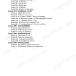
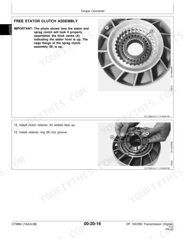
| Torque Converter | 46-68 | Drive Plate Group, Fixed Stator Assembly, Free Stator Assembly, Impeller, Front Cover |
| Charge Pump | 69-82 | Suction Tube Group, Auxiliary Pump Drive, Charge Pump Assembly |
| Front Cover Group | 83-105 | Input Assembly, Idler Gears, Driven Gear and Bearing, Magnetic Pickup |
| Control Valve | 107-113 | Cap Screw Tightening Sequence, Pressure and Temperature Check Ports |
| Main Case Front Housing | 115-139 | Output Yoke, Cylinder Housing, Bore Sleeves, Bearing Cup |
| Output Group and Clutch Stages | 141-177 | Clutch Stage Assemblies, Seal Rings, Disconnect Shaft, Shift Collar |
| Main Case Rear Housing | 179-193 | First Stage Cover Group, Bearing Retainer, Output End Play |
| Brake Group | 195-199 | Disc Brake Disassembly and Assembly |
| Special Tools | 201-211 | Assembly Stand Plate, Suction Leak Test, Clutch Solenoid Voltage Requirements |
| Test and Troubleshooting | 213-224 | Symptom Problem Solution Charts, Power Flow Diagrams, Clutch Calibration |
| Transmission Control Unit (Digital) | 225-243 | Engagement Override Valve, Engine Speed Magnetic Pickup, System Errors, Diagnostic Codes, Control Unit Mounting |
| CTM147 - DF150/DF250 Transmissions (Analog) | 249-489 | General Information, Transmission Mounting, Torque Converter, Charge Pump, Front Cover, Control Valve, Main Case Front Housing, Gear Ratio Group, Main Case Rear Housing, Brake Group, Special Tools, Test and Troubleshooting |
| CTM148 - DF150 Transmission, Analog Valve System | 490-730 | General Information, Transmission Mounting and Sensors, Charge Pump, Direct Drive Input Assembly, Control Valve, DF150 Gear Ratio Group, Main Case Housings, Brake Group, 8-4 Power Flow Diagrams, Clutch Calibration, Special Tools |
| CTM149 - DF250 Transmission, Analog Valve System | 731-958 | General Information, DF250 Ratings and Pressures, Charge Pump, Direct Drive Input Assembly, Control Valve, DF250 Gear Ratio Group, Main Case Housings, Brake Group, 4-4 and 8-4 Power Flow Diagrams, Transmission Control Unit, Special Tools |
| CTM157 - Transmission Control Unit Diagnostics | 959-1219 | Control Unit and Accessories, Proportional Valve Pinouts, Transmission Wiring Harness Diagrams, J6 Connector, Transient Voltage Protection, Test and Troubleshooting, Diagnostic Codes 105 to 199, Index |
Quick Reference Specifications
| Specification | Value | Page |
|---|---|---|
| DF-150 | ||
| Weight | 567 Kg (1250 lbs) | p. 17 |
| Input-to-Output Length | 500 mm (19.69 in) | p. 17 |
| Maximum Input Power | 142 kW (190 SAE hp) | p. 17 |
| Maximum Input No Load Speed | 3000 rpm | p. 17 |
| Maximum Turbine Torque | 1288 N-m (950 lb-ft) | p. 17 |
| DF-150/250 | ||
| Torque Converter Size | 298.5 mm (11.75 in) | p. 17 |
| Minimum Operating Temperature | -40°C (-40°F) | p. 18 |
| Maximum Continuous Operating Temperature | 110°C (230°F) | p. 18 |
| Normal Operating Temperature | 38-93°C (100-200°F) | p. 18 |
| Pump Pressure | 1758-1965 kPa (255-285 psi) | p. 18 |
| Pump Flow | 87-102 L/min (23-27 gpm) | p. 18 |
| Clutch Pressure | 1689-1931 kPa (245-280 psi) | p. 18 |
| Initial Oil Fill Volume | 19 liters (5 gal) | p. 25 |
| First Oil and Filter Change Interval | 50 hours | p. 27 |
| Routine Filter and Oil Change Interval | every 1000 hours | p. 27 |
| Oil Temperature Warning Signal (Converter Oil-Out) | 121°C (250°F) | p. 29 |
Funk DF150, DF250 Common Problems This Manual Covers
Transmission will not downshift or shifts erratically through the 4 forward/4 reverse ranges
Before tearing into the box, run the clutch calibration and check clutch solenoid voltage per the Test and Troubleshooting section. Downshift complaints on these units frequently trace to selector or calibration faults, not mechanical wear inside the clutch stages.
Manual Section: Test and Troubleshooting p. 223Converter oil running hot, overheat warning at 121C (250F)
Work the symptom/problem/solution charts systematically: verify the 19 liter fill level, confirm pump pressure sits in the 1758-1965 kPa range at the control valve check ports, then inspect cooling flow and the temperature sender before blaming the converter itself.
Manual Section: Test and Troubleshooting p. 29Intermittent TCU faults or system errors even though the machine starts and drives
The Transmission Control Unit section covers system errors, diagnostic codes, the engagement override valve, and the engine speed magnetic pickup. Connector and wiring faults can persist while the machine still runs, so check pickup gap and harness connections before replacing the TCU.
Manual Section: Transmission Control Unit (Digital) p. 231Play or clunk at the output yoke after high hours
The Main Case Rear Housing section covers the first stage cover group, bearing retainer, and the output end play check. Set end play to spec during reassembly, and inspect the output yoke and bearing cup in the front housing while the case is open.
Manual Section: Main Case Rear Housing p. 189Frequently Asked Questions
Does this manual cover the TCU diagnostic error codes for the DF150/DF250?
Yes. This set covers BOTH control generations - digital (CTM84) and analog (CTM147/148/149) - plus the dedicated CTM157 TCU diagnostics volume with fault codes 105 to 199. The Transmission Control Unit section covers system errors and diagnostic codes, plus the engagement override valve and the engine speed magnetic pickup that feed the TCU its signals. The Test and Troubleshooting section backs it up with symptom/problem/solution charts, so you can work from what the machine is doing back to the electrical or hydraulic cause instead of guessing. p. 231
Is the clutch calibration procedure in here? My shifts are getting harsh.
It is. The Test and Troubleshooting section covers clutch calibration and clutch solenoid voltage checks. On these digitally controlled boxes, harsh or delayed shifts are often a calibration issue, not worn clutches, so run the calibration before you pull the transmission. The manual also gives you the pressure check ports on the control valve so you can verify clutch pressures with a gauge while you are at it. p. 223
What is the oil capacity and how often do I change the fluid?
Initial fill is 19 liters (5 gal), listed on page 25. Change the oil and filter at 50 hours on a new or rebuilt unit to flush out break-in debris, then every 1000 hours after that (page 27). Stick to the 50 hour first change on a fresh rebuild - it is cheap insurance for the clutch packs and the charge pump. p. 25
What should charge pump pressure be, and how do I check it?
Pump pressure spec is 1758-1965 kPa (255-285 psi), from page 18. The Control Valve section identifies the pressure and temperature check ports so you can tee in a gauge without pulling anything apart. Low pressure points you at the charge pump, suction tube group, or internal leakage past the seal rings on the clutch stages - the troubleshooting charts walk you through narrowing it down. p. 111
At what temperature is this transmission actually overheating?
The converter oil-out overheat warning is 121C (250F), per page 29. If you are hitting that, the manual's troubleshooting charts help you sort out whether it is low fluid, a cooling problem, a slipping clutch, or a bad temperature sender before you condemn the converter. Overheating on these units rarely has just one cause, so work the chart in order. p. 29
Does this cover both the digital and analog control versions?
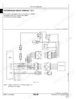
Yes. The main book is CTM84 (digital TCU control DF150/DF250). Bound in after its index is CTM148, a companion analog-control supplement for the DF150, plus CTM157 with the transmission wiring harness diagrams for the TCU system. p. 495