


Part of the John Deere Repair Manuals.
Need the factory rebuild specs for your John Deere 410D or 510D backhoe loader? This 976-page repair manual (OEM #TM1513) covers the complete machine: loader, backhoe, transaxle, axles, steering, brakes, electrical, and cab systems. Inside you get full wiring diagrams for every circuit, hydraulic schematics tracing fluid routing from the main radial piston pump through the loader and backhoe control valves, and a torque section covering everything from ROPS hardware to four-bolt flange fittings. Page after page of exploded views walks you through the transaxle, MFWD axle assemblies, and backhoe cylinders with complete disassemble-and-assemble sequences. Set main hydraulic system pressure to 19,000 kPa (2755 psi) and snug the pump drive shaft coupling to exactly 40 N·m: factory numbers, not forum estimates. Your machine is down. Bookmarked and keyword-searchable, open it on your tablet, walk to the backhoe, and get back to digging.
What's Inside This John Deere 410D, 510D Repair Manual
| System | Pages | Key Topics |
|---|---|---|
| General Information | 8-74 | Safety Information, Handle Fluids Safely-Avoid Fires, Prevent Battery Explosions, Prepare for Emergencies, Prevent Acid Burns, Handle Chemical Products Safely, Avoid High-Pressure Fluids, Park Machine Safely |
| Wheels | 75-85 | Powered Wheels and Fastenings, Rear Wheel Assembly, Front Wheel Assembly, Tire |
| Axles and Suspension Systems | 86-218 | Non-Powered Front Axle, Axle Bushings, Powered Front Axle, Powered Wheel Axle, Rear Axle |
| Transmission | 219-417 | Transaxle, Reverser with Torque Converter |
| Engine | 418-454 | Engine with Reverser, Fuel System |
| Engine Auxiliary Systems | 455-480 | Cold Weather Starting Aids, Engine Coolant Heater, Starting Aid Nozzle, Starting Aid Solenoid |
| Torque Converter | 481-484 | Turbine, Gears and Shafts |
| Steering System | 485-520 | Steering Column, Tilt Steering Column, Steering Valve, Non-Powered Axle Steering Cylinder, Steering Cylinder Bushings, APL745 MFWD Axle Steering Cylinder, APL2035 MFWD Axle Steering Cylinder, Tracking Angle for MFWD Axle |
| Service Brakes | 521-549 | Brake Piston Housing and Disk, Brake Disk and Pressure Plate, Transaxle Case Braking Surface, Transaxle Case Clean-Up Procedure, Pressure Test Brake Pressure Plate |
| Park Brake | 550-576 | Park Brake Cross Section, Park Brake Active Elements, Park Brake Active Element |
| Electrical Systems | 577-622 | Batteries |
| Frames | 623-636 | Frame Installation, Welding Repair of Major Structures |
| Operator’S Station | 637-726 | Cab or ROPS |
| Sheet Metal and Styling | 727-737 | Hood And Engine Enclosure, Miscellaneous Shields, Steps, Battery Box, MFWD Shaft Guard, Grille And Grille Housing, Fenders |
| Safety, Convenience and Miscellaneous | 738-743 | Radio, Radio and Speakers, Antenna |
| Main Hydraulic System | 744-768 | Charge Pump, Hydraulic Pump, Pump Drive Shaft, Stroke Control Valve Housing, Destroke Solenoid, Crankcase Relief Valve, Pressure Compensator Valve, Priority Valve |
| Loader | 769-837 | Bucket, Loader Bucket, Cutting Edge |
| Backhoe | 838-976 | Bucket, Bucket and Bucket Links, Bucket Bushings, Bucket Tooth Shank, Bucket Cutting Edge |
Quick Reference Specifications
| Specification | Value | Page |
|---|---|---|
| All Models | ||
| Hydraulic System Pressure setting | 19 000 kPa (2755 psi) | p. 32 |
| Pump Drive Shaft-to-Coupling Cap Screw Torque | 40 N·m (30 lb-ft) | p. 744 |
| Cooling System Capacity | 16 L (17 qt) | p. 422 |
| Brake Valve Check Valve Seat Torque | 34 N·m (25 lb-ft) | p. 544 |
| Steering Valve Check Valve Plug Torque | 11 N·m (100 lb-in.) | p. 485 |
| Engine Coolant Capacity | 16 L (17 qt) | p. 419 |
| Engine Oil Capacity (including filter) | 8.5 L | p. 57 |
| Fuel Tank Capacity | 129 L | p. 57 |
| 410D, 510D (SN 801200-) | ||
| Bucket Dump Circuit Relief Pressure | 31030 kPa (310 bar) (4500 psi) | p. 801 |
| 410D Std. Lift | ||
| Crowd Cylinder-410D Std. Lift Piston Cap Screw Snug Torque (Initial) | 300 N·m (220 lb-ft) | p. 884 |
| 410D Hvy. Lift and 510D | ||
| Crowd Cylinder-410D Hvy. Lift and 510D Rod Guide Cap Screws Torque | 570 N·m (420 lb-ft) | p. 884 |
| 410D SN 796855-, 510D SN 796891- | ||
| Hydraulic Reservoir Capacity | 41 L | p. 762 |
John Deere 410D, 510D Common Problems This Manual Covers
Hydraulic system pressure drops randomly during backhoe operation, boom drifts or hesitates
Test system pressure at the pump outlet; it should hold steady at 19,000 kPa (2755 psi) per page 32. If low, remove and inspect the charge pump on page 744 before condemning the main pump. Clean the hydraulic filter and check the reservoir for metal particles or water contamination.
Manual Section: Main Hydraulic System p. 744Engine coolant temperature rises abnormally fast at normal load, gauge pegged high
Check coolant level first: system holds 16 L (17 qt) per page 422. Inspect the radiator core for debris and verify the thermostat is opening correctly. Check the water pump impeller for erosion or cavitation damage. If the block is clear but temperature still climbs, follow the engine removal procedure on page 418 to access internal cooling passages.
Manual Section: Engine p. 418Brake pedal feels spongy or travel increases, machine won't stop within safe distance
Remove and inspect brake piston housing per the Service Brakes section starting on page 521. Check brake disk thickness and condition of the pressure plate. Torque the brake valve check valve seat to 34 N·m (25 lb-ft) per page 544 during reassembly. Pressure test the brake system after repair to verify activation pressure before returning the machine to service.
Manual Section: Service Brakes p. 521Steering feels heavy and wanders at speed, constant corrections needed on flat road
Inspect the steering valve on page 485 for internal leakage before pulling the cylinder. Torque the check valve plug to 11 N·m (100 lb-in.) during reassembly. On MFWD-equipped machines, verify front wheel toe-in is within 6 ± 3 mm per page 118; misalignment causes tire wear and wandering that mimics a steering valve fault.
Manual Section: Steering System p. 485Frequently Asked Questions
Torque specs for John Deere 410 backhoe hydraulic fittings?
The manual provides various torque specifications for hydraulic fittings. For 37° Flare and 30° Cone Seat Connectors, a 3/8 - 24 UNF fitting requires 8 N·m (6 lb-ft) of torque. For Flat Face O-Ring Seal Fittings, a 6.35 mm (0.250 in.) nominal tube O.D. requires a Swivel Nut torque of 16 N·m (12 lb-ft) and a Bulkhead Nut torque of 5.0 N·m (3.5 lb-ft). For Inch Series Four Bolt Flange Fittings, a 1/2 Nominal Flange Size with a 5/16-18 UNC Cap Screw requires 20-31 N·m (15-23 lb-ft). For Metric Series Four Bolt Flange Fittings, an M6 thread requires 12 N·m (9 lb-ft). p. 63
What are the replacement specifications for Crowd cylinder?
For the 410D Standard Lift Crowd Cylinder, the dry weight is 59 kg (130 lb) with a barrel and rod size of 100 mm x 56 mm. The Piston Cap Screw requires an initial snug torque of 300 N·m (220 lb-ft) and a final torque turn of 1/4 turn (90°). For the 410D Heavy Lift and 510D Crowd Cylinder, the dry weight is 97 kg (213 lb) with a barrel and rod size of 115 mm x 63 mm. The Spanner Nut torque for both is 170-237 N·m (125-175 lb-ft). p. 884
What are the replacement specifications for Hydraulic pump seals?
While specific replacement specifications for hydraulic pump seals (e.g., dimensions, materials) are not detailed, the manual does provide information on tools and torque for related components. The Hydraulic Pump-to-Support Cap Screws require a torque of 130 N·m (96 lb-ft). Tools such as the Hydrostatic Pump Input Shaft Seal Installation Tool JD321 (page 481) and Lip Seal Installation Tool JDG804 (page 883) are specified for installing seals in the control valve and converter shaft. p. 744
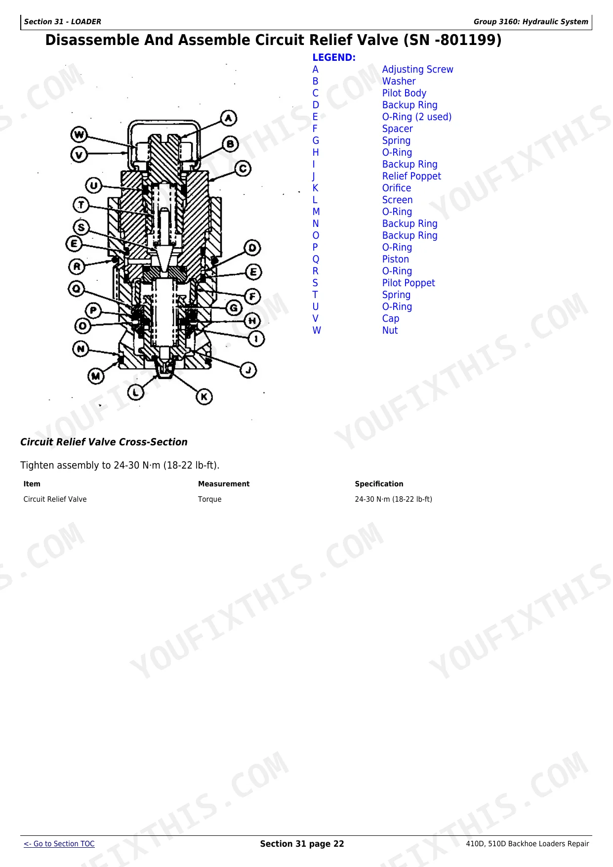
How do you fix john Deere 410D 510D crowd cylinder rebuilds every 10-20 hours, internal seals weeping oil?
Inspect the crowd cylinder bore for scoring and measure internal seal clearance before ordering parts. Verify hydraulic system pressure holds at 19,000 kPa (2755 psi) per page 32: low pressure accelerates seal wear. During rebuild, torque the piston cap screws to the values on page 884, which differ by machine configuration. p. 838
What format is this manual in?
A 976-page Repair Manual in searchable PDF format, available the moment you complete checkout. View on computer, tablet, or phone, with no shipping wait.
Am I able to print pages from this manual?
Yes. The PDF has no DRM restrictions, so print any page or section you need for your shop. Works with any standard printer.
Are there hydraulic schematics in this John Deere 410D, 510D manual?
Yes, complete hydraulic schematics with flow diagrams, valve configurations, and pressure specifications are included.


