


Part of the John Deere Repair Manuals.
This is the John Deere 310G Backhoe Loader repair technical manual, TM1886, a 780 page factory service reference for the machine and its POWERTECH 4.5L and 6.8L diesel engines.It walks through removal, repair, and installation across the full machine: wheels, axles and MFWD suspension, the power shift transmission and torque converter, engine and auxiliary systems, steering, service brakes, electrical systems, the operator's cab, the main hydraulic system, and both the loader and backhoe. Weights, clearances, and torque values are listed at the start of each group.This volume is the repair half of the set, so base engine internals are covered separately in CTM104. For the 310G owner or shop rebuilding hydraulics, driveline, or structure, it gives the exact procedures and specifications the factory intends.
What's Inside This John Deere 310G Manual
| System | Pages | Key Topics |
|---|---|---|
| General Information | 9-28 | Safety Information (Safety Features, Recognize Safety Information, Follow Safety Instructions, Operate Only If Qualified, Wear Protective Equipment) |
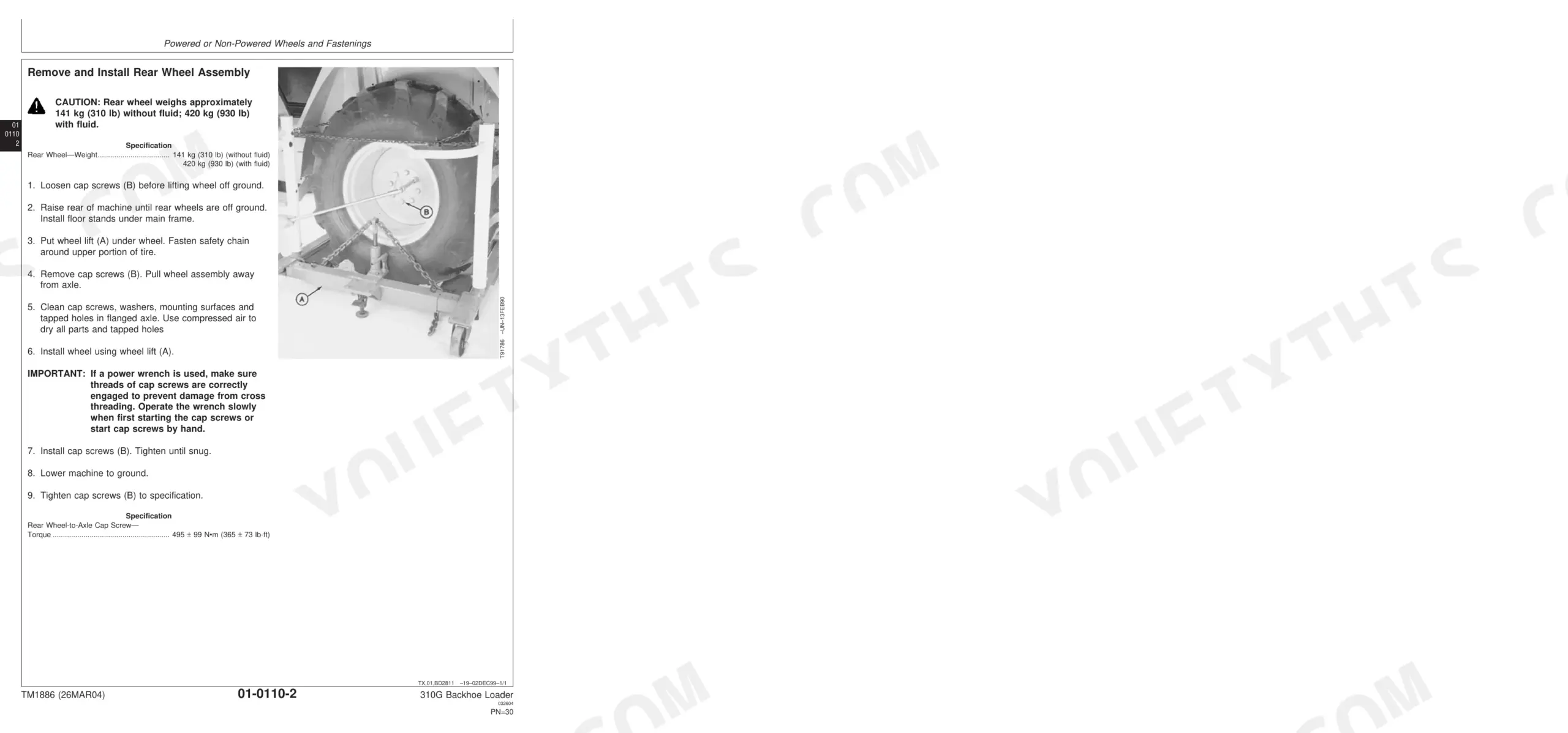
| Wheels | 29-38 | Service Equipment and Tools, Specifications, Rear Wheel Assembly, Front Wheel Assembly, Tire |
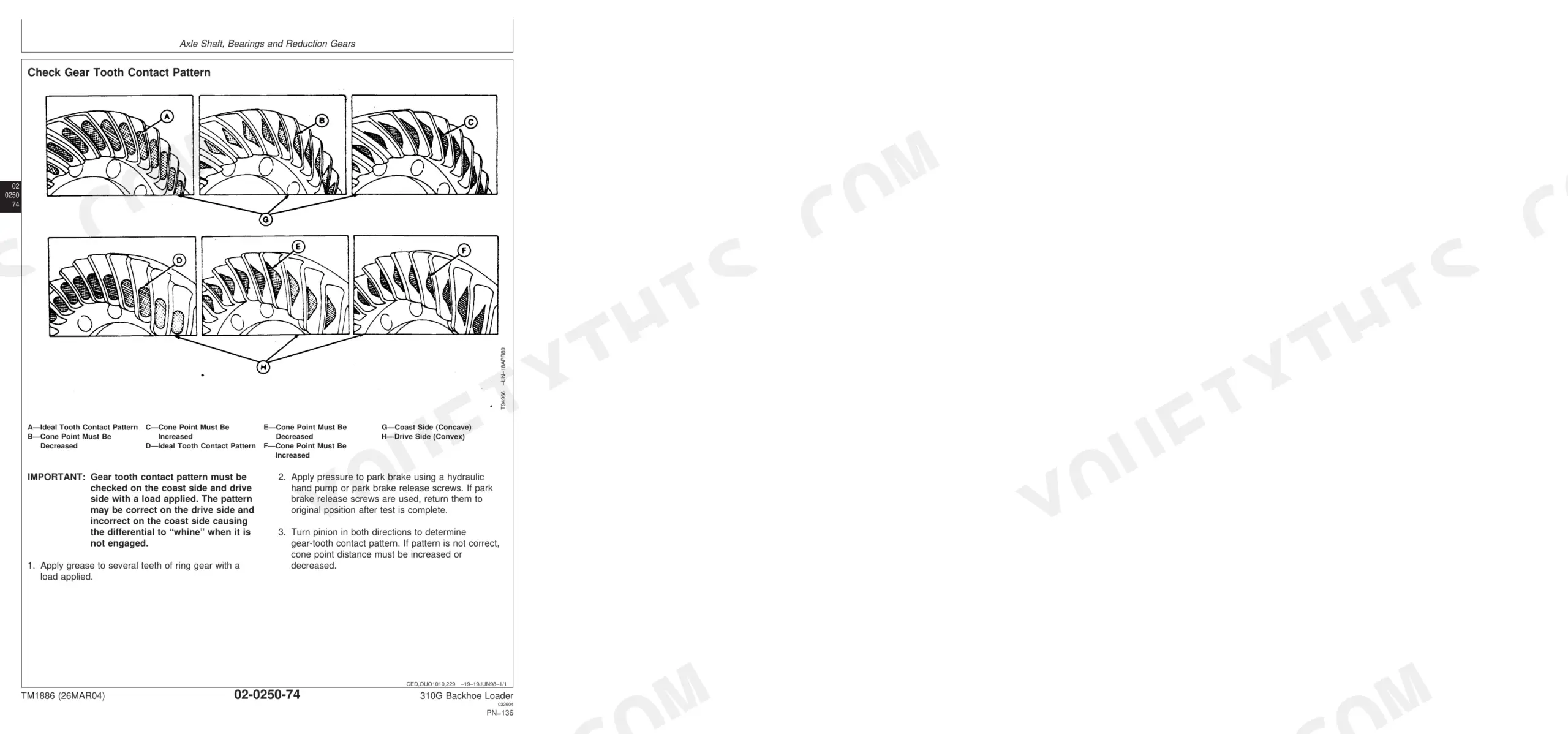
| Axles and Suspension Systems | 39-138 | Input Drive Shafts and U-Joints, Non-Powered Wheel Axles, Powered Wheel Axle (MFWD), Axle Shaft, Bearings and Reduction Gears, Service Brakes, Check Gear Tooth Contact Pattern |
| Transmission | 139-234 | Removal and Installation, Controls Linkage, Input Drive Shafts and U-Joint, Gears, Shafts, Bearings, And Power Shift Clutch, Hydraulic System |
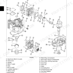
| Engine | 235-256 | Powertech 4.5L (4045) and 6.8L (6068) John Deere Engines, Service Equipment and Tools, Specifications, PowerTech 4.5 L (4045) John Deere Engine, Use CTM104 |
| Engine Auxiliary Systems | 257-290 | Cold Weather Starting Aid, Cooling System, Speed Controls, Intake System, Exhaust System, External Fuel Supply System |
| Torque Converter | 291-294 | Other Material, Remove and Install Torque Converter, Disassemble and Assemble Torque Converter |
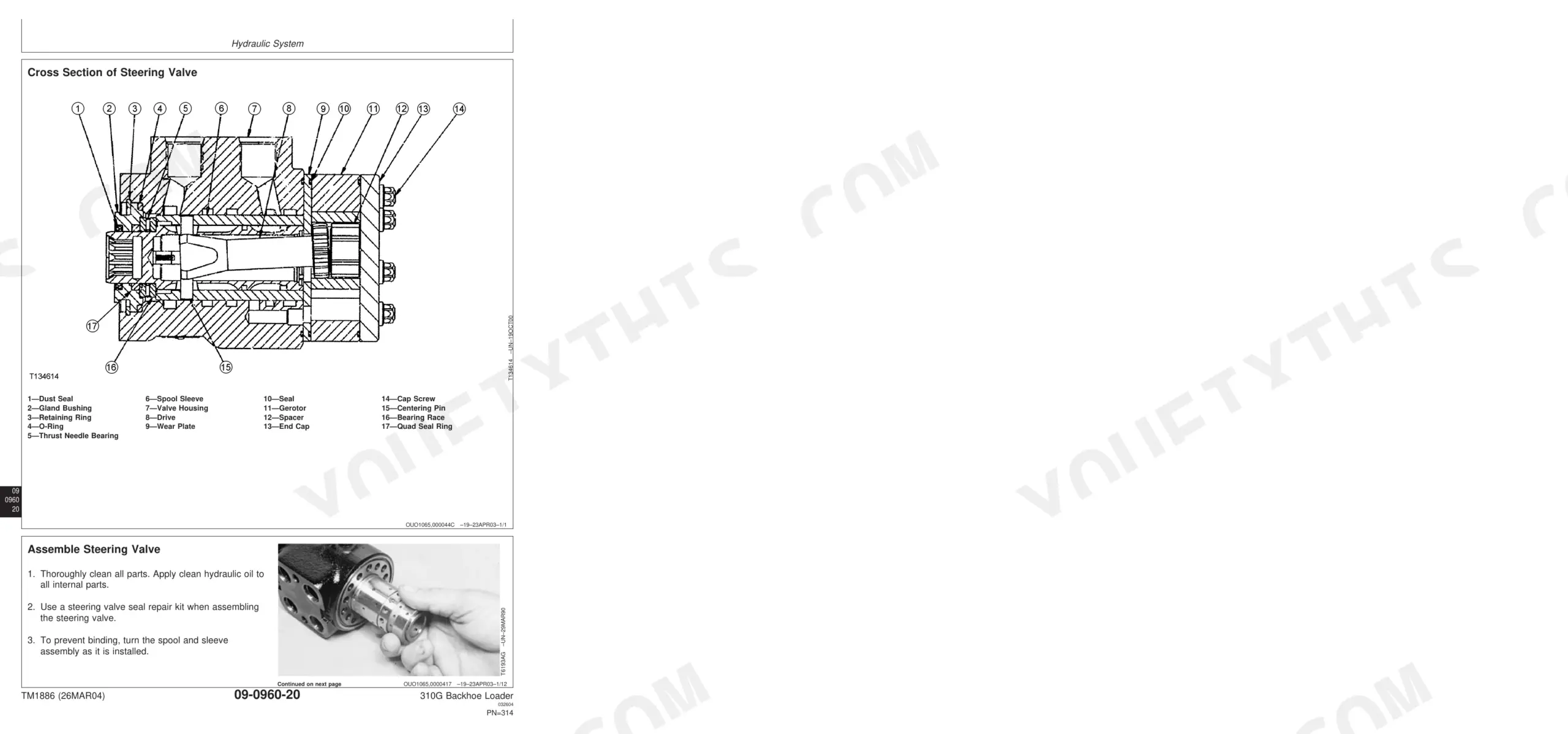
| Steering System | 295-340 | Steering Cylinder Repair for Front Wheel Drive Axles, As and Ms Series, Steering Column, Steering Valve, Non-Powered Axle Steering Cylinder, Apl-2025 MFWD Axle Steering Cylinder |
| Service Brakes | 341-364 | Active Elements, Hydraulic System, Service Brake, Brake Valve, Brake Pedals, Bleeding Brakes |
| Electrical Systems | 365-400 | Batteries, Alternator, Wiring Harness, Connectors, Fuel Gauge Sender, Starter Motor |
| Frames, Chassis or Supporting Structure | 401-410 | Welding Repair of Major Structures, Rivnut® (Kremnut) Fasteners, Main Frame Bushings, Counterweight |
| Operator's Station | 411-512 | Cab/ROPS, Wiper Motor, Windowpanes, Seat Assembly, Air Conditioning Compressor, Heater Core |
| Sheet Metal and Styling | 513-526 | Hood, Engine Enclosure, Battery Box, Grille, Fenders, Cab Skirt |
| Safety, Convenience and Miscellaneous | 527-536 | Radio, Speakers, Antenna, Horn, Back-Up Alarm |
| Main Hydraulic System | 537-560 | Hydraulic Pump, Hydraulic Filter, Reservoir, Hydraulic Oil Coolers, Transmission Oil Coolers |
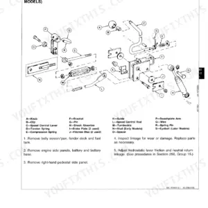
| Loader | 561-654 | Boom Cylinder, Loader Bucket, Loader Control Valve Linkage, Bucket Curl and Boom Raise Circuit Relief Valve, Ride Control Valve |
| Backhoe | 655 | Bucket, Bucket Links, Backhoe Valve Linkage, Dipperstick, Boom, Swing Frame |
| Dealer Fabricated Tool | 8 | DFT1146 Axle Mounting Bracket, DFT1147 Axle Rolling Torque Bar, DFT1143 Transmission Support Bracket, DFT1163 MFWD Snap Ring Removal and Installation Tool |
Quick Reference Specifications
| Specification | Value | Page |
|---|---|---|
| Fuel Tank Drain Screw—Torque | 59 N•m (44 lb-ft) | p. 287 |
| Fuel Tank Mounting Cap Screws—Torque | 59 N•m (44 lb-ft) | p. 287 |
| Hydraulic Pump—Weight | 30 kg (65 lb) Approximate | p. 141 |
| Filter Mounting Cap Screws—Torque | 33 ± 4 N•m (24 ± 3 lb-ft) | p. 547 |
| Hydraulic Reservoir—Weight | 27 kg (60 lb) Approximate | p. 550 |
| Backhoe Swing Section Spool End Screw—Torque | 9.5 N•m (84 lb-in.) | p. 719 |
| Engine Coolant Temperature Switch—Torque | 81 N•m (60 lb-ft) | p. 385 |
| Rear Wheel Weight (without fluid) | 141 kg | p. 31 |
| Drive Shaft Cap Screws Torque | 41 N•m | p. 41 |
| Axle Pivot Pin Cap Screw Torque | 215 N•m | p. 54 |
| Rear Axle Service Brake Disk Thickness | 5 mm Minimum | p. 68 |
| Transmission Weight | 227 kg Approximate | p. 141 |
John Deere 310G Common Problems This Manual Covers
Backhoe and stabilizers slow to lift
Stabilizers or the backhoe that will not raise or lower despite correct oil level usually point to a valve fault, crossed lines, or debris in the circuit. The main hydraulic system section covers the pump, filter, and reservoir.
Manual Section: Main Hydraulic System p. 537Hesitant or failed backhoe swing
A swing that engages slowly or not at all often traces to the swing circuit valve or worn linkage. The backhoe section covers the swing frame, control valve linkage, and cylinders.
Manual Section: Backhoe p. 655Engine drags and struggles to start
Hard starting with the engine dragging can mean blocked fuel delivery, a contaminated tank, or a failing lift pump. The engine auxiliary systems section covers the external fuel supply system.
Manual Section: Engine Auxiliary Systems p. 257No power to ECU or pump
A no-signal condition often comes from a poor ground, a broken supply, or high resistance in the ECU to pump wiring. The electrical systems section covers batteries, wiring harness, and connectors.
Manual Section: Electrical Systems p. 365Sluggish reverse or gear engagement
Delayed or weak engagement can indicate aerated or degraded oil, or wear in the power shift clutch. The transmission section covers the clutch, gears, shafts, and hydraulic control valve.
Manual Section: Transmission p. 139Weak or spongy service brakes
A soft pedal or reduced braking on a backhoe loader usually needs bleeding or brake valve service. The service brakes section covers the brake valve, pedals, and bleeding procedure.
Manual Section: Service Brakes p. 341Frequently Asked Questions
What machine and engines does this manual cover?
It is the repair technical manual, TM1886, for the John Deere 310G Backhoe Loader with the POWERTECH 4.5L and 6.8L diesel engines. Base engine internals are documented separately in CTM104.
Does it cover hydraulic repair and torque specs?
Yes. The main hydraulic system section covers the pump, filters, reservoir, and coolers, with weights and torque values listed at the start of each group for the loader and backhoe circuits. p. 537
Can I troubleshoot the electrical system and ECU wiring?
Yes. The electrical systems section covers batteries, alternator, starter, wiring harness, and connectors, which is where ECU power and ground faults are traced. p. 365
Does it include the transmission and torque converter?
Yes. The transmission section covers removal, controls linkage, gears, shafts, and the power shift clutch, and a separate section covers the torque converter. p. 139
How quickly can I access this manual after buying?
Immediate download of the complete 780-page searchable Technical Manual. Access it on any device, from a laptop at your desk to a phone in the field.
Can I print this manual?
Absolutely. No DRM or copy protection. Print the whole manual or just the pages you need. Any home or office printer works.
Can I find hydraulic circuit diagrams in this John Deere 310G manual?
A hydraulic system diagram for the John Deere 310G is included.


Reviews
There are no reviews yet.