
Part of the John Deere Repair Manuals.
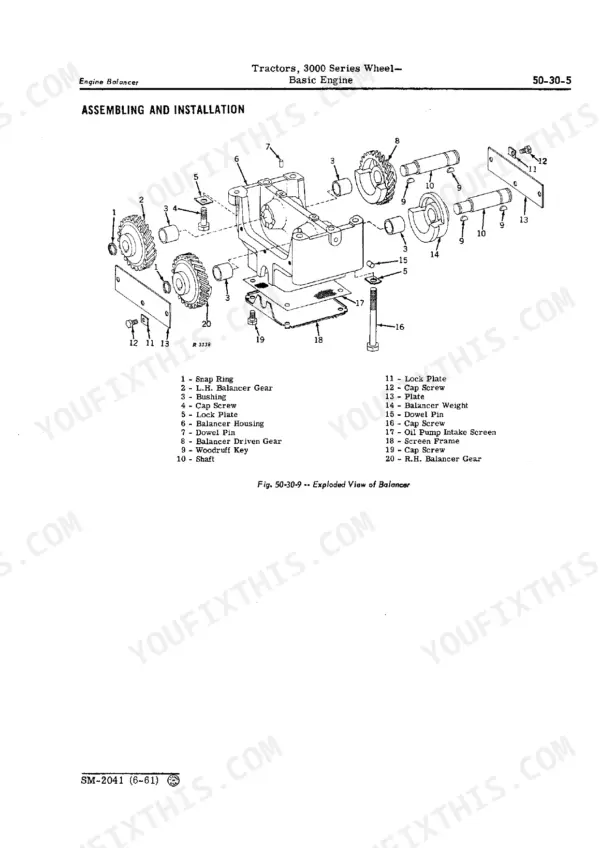
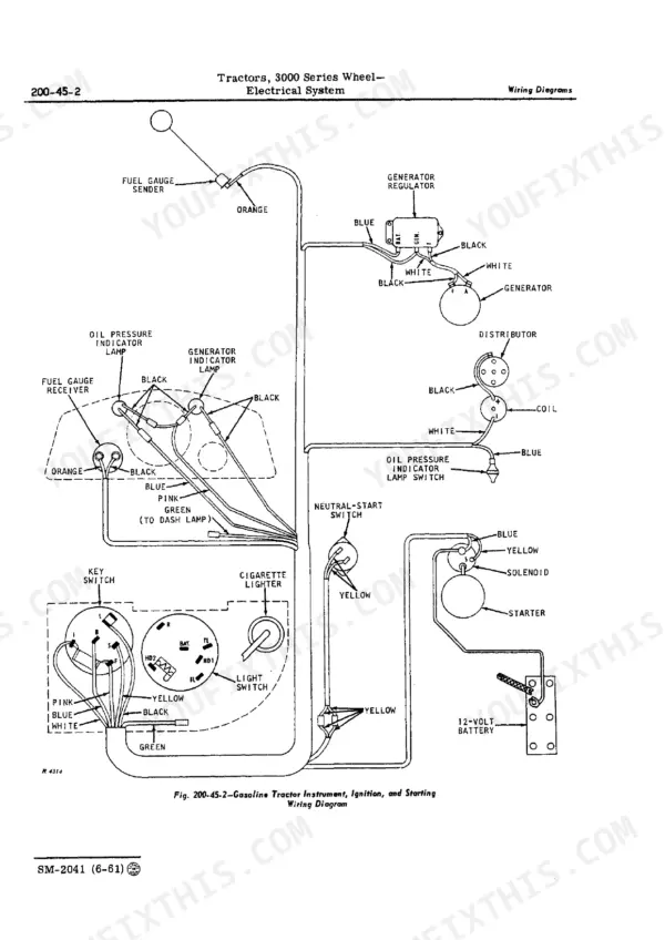
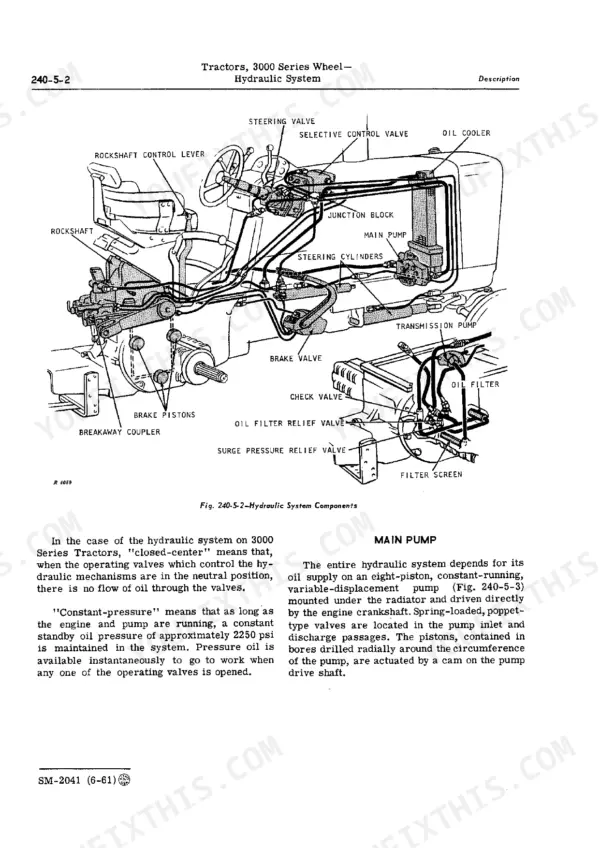
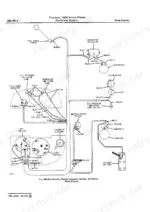
Rockshaft dropping a mounted implement halfway through a field pass? The John Deere 3000, 3010 service manual PDF answers it across 662 pages of factory procedure for these wheel tractors, covering both the gasoline and diesel builds. Wiring diagrams trace the ignition, generator, regulator and lighting circuits end to end, while hydraulic schematics follow oil from the reservoir through the transmission and main pumps into power steering, power brakes and the remote cylinder selective control valve. Troubleshooting charts close out the book, letting you work backward from a symptom in the engine, clutch, transmission or electrical system. Set injection nozzle holes at 0.011 in.; pull flywheel to crankshaft cap screws to 85 ft.-lbs. A guess costs you a second teardown and a ruined component. Bookmarked and searchable, the exploded views show you exactly which piece failed, so you order right the first time and finish the field before the weather turns.
What's Inside This John Deere 3010, 3000 Manual
| System | Pages | Key Topics |
|---|---|---|
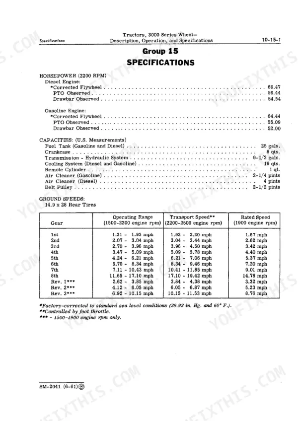
| Description, Operation, and Specifications | 5-22 | Description |
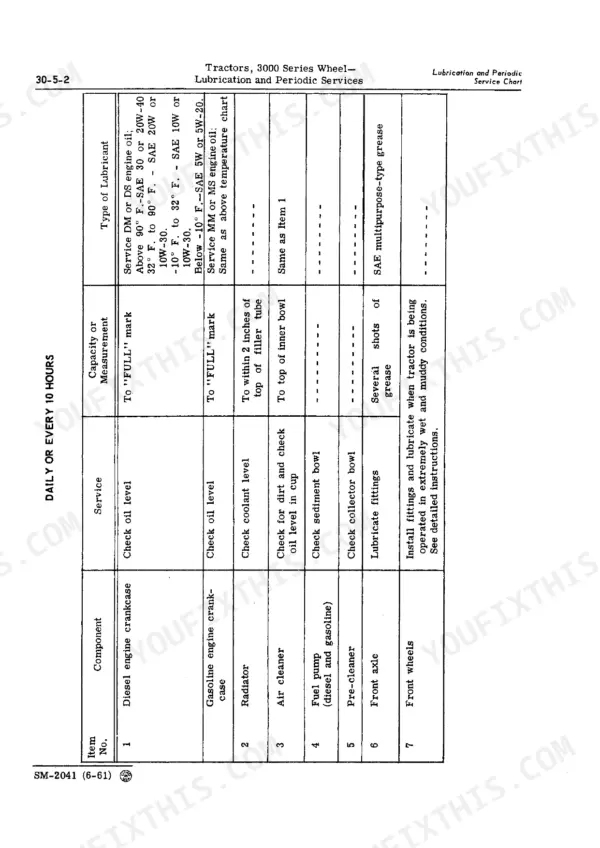
| Lubrication and Periodic Services | 23-38 | Lubrication and Periodic Service Chart, Detailed Periodic Services |
| Engine Tune-Up and Tractor Adjustments | 39-60 | Description, Engine Tune-Up |
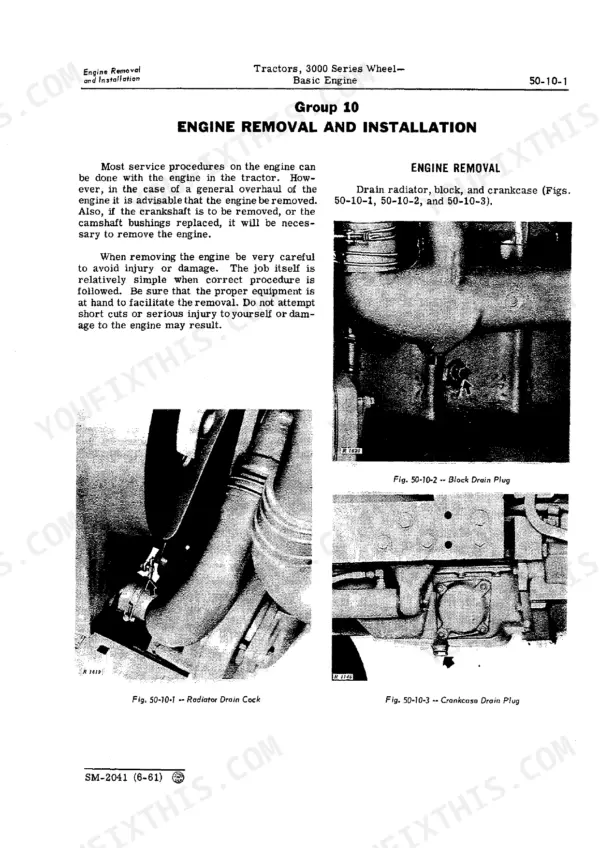
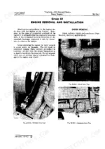
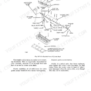
| Basic Engine | 61-136 | Description, Engine Removal and Installation, Cylinder Head, Valves, And Manifold, Pistons, Connecting Rods, And Blocks |
| Engine Lubrication System | 137-148 | Description, Oil Pump, Oil Filter Assembly |
| Governor, Crankcase Ventilator Pump, and Throttle Linkage | 149-160 | Description, Service |
| Cooling System | 161-172 | Description and Servicing, Radiator, Pressure Cap, And Fan, Water Pump and Thermostat |
| Gasoline Fuel System | 173-214 | Description, Gasoline Tank and Lines, Fuel Pump, Gasoline Carburetor, Air Cleaner |
| Diesel Fuel System | 215-240 | Description and Operation, Fuel Tank and Lines, Injection Pump and Governor, Injection Nozzles, Fuel Filter and Pump Assemblies |
| Engine Clutch | 241-268 | Description and Operation, Clutch Shafts and Controls, Clutch Assembly |
| Power Take-Off (PTO) Clutch | 269-272 | Description and Operation, Servicing the Power Take-Off Clutch |
| Collar-Shift Transmission | 273-310 | Description and Operation, Shifter Controls and Gear Shifters, Shafts and Gears |
| Differential | 311-318 | Description and Operation, Servicing the Differential |
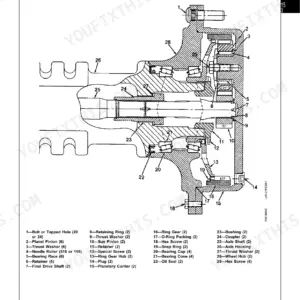
| Final Drives | 319-328 | Description and Operation, Servicing the Final Drive System |
| Power Take-Off (PTO) and Belt Pulley | 329-354 | Description and Operation, Servicing the Power Take-Off, Belt Pulley Assembly |
| Sheet Metal | 355-370 | Description, Cowl and Dash, Hood and Grille, Platform, Fenders |
| Electrical System | 371-440 | Description, Electrical Tests on the Tractor, Ignition System, Generators, Generator Regulators, Starters, Batteries, Lighting and Accessory Systems |
| Seats | 441-456 | Description, Regular Seat, Deluxe Seat |
| Front Axles | 457-462 | Front Axle Assembly |
| Wheels, Tires, and Weights | 463-472 | Front Wheels, Rear Wheels, Tires and Weights |
| The Hydraulic System | 473-486 | Description, Testing the System |
| Hydraulic Supply System | 487-496 | Description and Operation, Reservoir and Filter, Check Valve, Oil Filter, And Surge Pressure Relief Valves, Oil Cooler, Pipes and Connections |
| Hydraulic Pumps | 497-522 | Transmission Pump, Main Hydraulic Pump |
| Power Steering | 523-546 | Description and Operation, Steering Valve, Steering Cylinders |
| Power Brakes | 547-562 | Description and Operation, Brake Valves and Pedals, Cylinders, Shoes, And Disks |
| Remote Cylinder Selective Control Valve | 563-582 | Description and Operation, Operating Valve |
| Breakaway Couplers and Remote Cylinders | 583-594 | Description, Breakaway Couplers, Remote Cylinders |
| Rockshaft and 3-Point Hitch | 595-622 | Description and Operation, Rockshaft Housing and Valve Assembly, Load Control Arm and Load Shaft, Point Hitch |
| Drawbar Assembly | 623-626 | Description and Service |
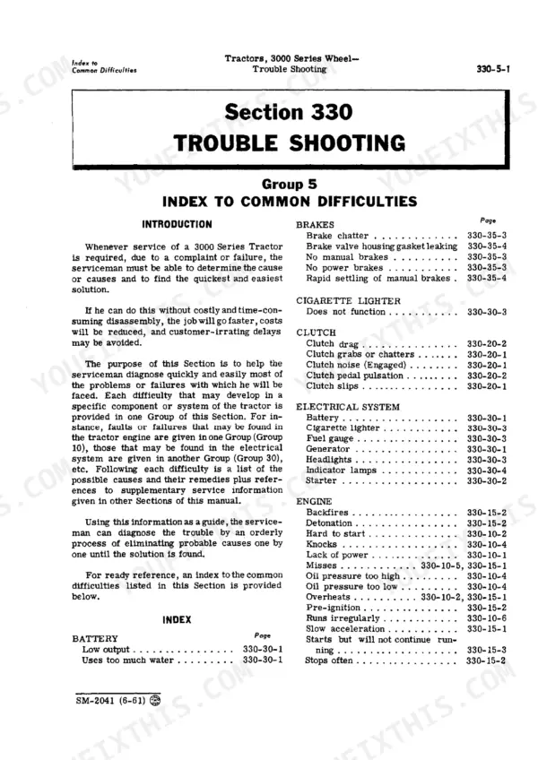
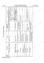
| Trouble Shooting | 627-662 | Index to Common Difficulties, Engine Difficulties, Ignition System Difficulties, Engine Clutch Difficulties, Transmission Difficulties, Electrical System Difficulties |
Quick Reference Specifications
| Specification | Value | Page |
|---|---|---|
| Flywheel to crankshaft cap screws | 85 ft.-lbs. torque | p. 267 |
| Nozzle holes | 0.011 in. | p. 240 |
| Diameter of drive gear | 2.312 to 2.316 in. | p. 147 |
| Diameter of driven and idler gears | 2.268 to 2.270 in. | p. 147 |
| Center hole in nozzle | 0.040 to 0.042 in. | p. 240 |
| Inside diameter of clutch shaft bushing | 1.205 to 1.207 in. | p. 267 |
| Diameter of drive dowels | 0.624 to 0.625 in. | p. 267 |
| Transmission case to clutch housing cap screws and nuts | 150 ft.-lbs. torque | p. 267 |
| 12-Volt Starter Pinion clearance | 0.010 to 0.140 in. | p. 439 |
| 12-Volt Starter Armature end-play | 0.005 to 0.050 in. | p. 439 |
| Knuckle spindle vertical end play | 0.036 in. maximum | p. 462 |
| Knuckle spindle end play adjusting washers | 0.036 in. thick | p. 462 |
John Deere 3010, 3000 Common Problems This Manual Covers
Power steering quits when the loader loads the system or the tractor bogs down
Verify pump supply before condemning the steering valve, since both circuits share oil. Test the unloading valve spring: 36 to 44 lb. compressed to 3-7/8 in. per page 546. Measure the steering valve piston at 3.370 to 3.372 in. against a 3.3740 to 3.3770 in. bore, and confirm front axle toe-in sits between 1/8 and 3/8 in.
Manual Section: Power Steering p. 523Cranks slowly or will not turn over, starter clicks and quits
Clean and torque the battery and ground cable ends first; corroded lugs fake a dead starter every spring. Trace the circuit on the wiring diagram. If the starter comes off, set pinion clearance to 0.010 to 0.140 in. and check armature end play, 0.005 to 0.050 in. on a 12-volt unit.
Manual Section: Electrical System p. 371Hard to shift, gears clash, or reverse will not engage
Inspect and adjust the shifter linkage for wear before you split anything. Run the checks in the transmission troubleshooting pages starting at 627, and confirm the engine clutch fully releases: measure disk thickness under load at 0.334 to 0.356 in. Torque transmission case to clutch housing fasteners to 150 ft.-lbs. on reassembly.
Manual Section: Collar-Shift Transmission p. 273Rockshaft raises slowly, settles under load, or will not lift the implement
Clean the filter and check oil level, then test rockshaft response per the procedures beginning on page 595. Look for bypassing at the piston packing and load control linkage. On reassembly, torque the two 9/16-inch piston cover cap screws to 115 ft.-lbs. and the four 1/2-inch screws to 85 ft.-lbs.
Manual Section: Rockshaft and 3-Point Hitch p. 595Frequently Asked Questions
How do you adjust the torque on a John Deere 3010 cylinder head?
To adjust the cylinder head cap screw torque, the engine should be hot. Tighten the cylinder head cap screws to 115 foot-pounds torque in the sequence shown in Figure 40-10-4. p. 48
What is the correct valve clearance for a gasoline engine on a John Deere 3010?
For a gasoline engine, the intake valve clearance should be 0.015-inch and the exhaust valve clearance should be 0.028-inch. p. 48
How do you fix john Deere 3010 hydraulic pump chatters, three-point hitch and power steering slow or intermittent?
Check reservoir level first, then work the testing procedures in the hydraulic system section starting on page 473 before pulling anything apart. Air drawn past a suction joint chatters the pump. Inspect the main pump per page 497, and measure valve bores against the 0.750 to 0.752 in. limit on page 582. p. 473
How do you fix engine fires, runs a few seconds, then dies during fieldwork?
Drain the water trap and change the fuel filter before chasing anything expensive. Test the transfer pump outlet: it should hold 2 to 4 psi as listed on page 240. If it falls short, pull the pump and check gear-to-body clearance against 0.002 to 0.006 in. on page 147, then bleed the lines. p. 215
Is this John Deere 3000 manual a PDF I download?
Straight to your device: 662 pages of searchable Service Manual, downloadable the moment payment goes through.
Can I print this John Deere 3000 manual?
Yes. Print the pages or sections you need for your own shop use. Any standard printer works.
Are there hydraulic schematics in this John Deere 3000 manual?
Included. Hydraulic system schematics cover all circuits, control valves, and component specifications for the John Deere 3000, 3010. See page 525 for an example.







Reviews
There are no reviews yet.