


Part of the John Deere Repair Manuals.
This is the complete John Deere factory diagnostic and repair manual (TM131019) for the 4044M, 4044R, 4049M, 4049R, 4052M, 4052R, 4066M and 4066R compact utility tractors. Across 2,285 pages it covers every system on these machines: engine teardown with piston, crankshaft, and valve specs; hydrostatic and power reverser transmission service; MFWD, differential, and PTO final drives; hydraulic system with rockshaft, range control, three-point hitch, and selective control valves; the full electrical system with wiring schematics and circuit diagrams; and complete ECU, ICC, PTH, and PTR diagnostic trouble code trees with step-by-step fault isolation routines. It is the same manual a John Deere dealer technician uses, with the torque values, bearing clearances, and pressure test specs that let you repair to factory tolerance the first time.
What's Inside This John Deere 4044M-4066R Repair Manual
| System | Pages | Key Topics |
|---|---|---|
| General Information | Safety Procedures, General References, Technical Specifications, Fuel and Lubricant Requirements, Serial Number Locations | |
| Engine Repair | Engine Removal and Installation, Rocker Arm Assembly, Cylinder Head Remove and Install, Valves and Valve Seats, Flywheel, Timing Gear Cover, Crankshaft and Main Bearings, Pistons and Connecting Rods, Camshaft, Cylinder Bore Inspection and Reboring | |
| Fuel, Air Intake, and Exhaust Repair | Fuel Pump, Fuel Filter, Water Separator, Fuel Injectors, Fuel Injection Nozzle, Injection Pump, Fuel Cooler, Fuel Tank, Air Cleaner, Turbocharger, Exhaust Valve Actuator | |
| Electrical Repair | Battery, Starter, Alternator, Electrical System Components, Wiring Harnesses | |
| Transmissions Repair | Separation, Hydrostatic Power Train, Power Reverser Transmission | |
| Final Drive Repair | MFWD, Differential, PTO | |
| Steering and Brake Repair | Steering System, Brakes | |
| Hydraulics Repair | Hydraulic Pump and Filter, Rockshaft, Range Control, Three-Point Hitch, Selective Control Valve | |
| Miscellaneous Repair | Hood and Side Panels, Fenders, Wheels | |
| Cab / Open Operator Station Repair | Seat and Support, Control Console, Roll-Gard, Cab Components, Open Operator Station Components, Heating System, Air Conditioning System, Temperature Control and Blower Motor | |
| Diagnostic Trouble Codes | ECU Engine Control Unit Codes, Icc Instrument Cluster Control Codes, Pth Hydrostatic Power Train Codes, Ptr Power Train Reverser Codes | |
| Observable Symptoms and System Diagnostics | Engine Diagnostics, Fuel and Cooling Diagnostics, Electrical Diagnostics, ECU Diagnostics, Drive Systems and Transmission Diagnostics, Steering and Brake Diagnostics, Hydraulic Diagnostics, Cab and Oos Diagnostics | |
| Engine Operation, Tests, and Adjustments | Calibrations, Preliminary and Operational Checks, Theory of Operation, Tests and Adjustments | |
| Fuel, Air, Exhaust, and Cooling Operation, Tests, and Adjustments | Calibrations, Theory of Operation, Component and Connector Information, Tests and Adjustments | |
| Electrical Theory, Schematics, and Component Information | Key Switch and Starter, Alternator, Accessory Power, Control Module, Headlights, Hydraulics and Rockshaft, Heating and AC, Cruise Control, Windshield Wiper, Icc, MFWD, Brakes, PTO, Speed Sensor, ECU, Tcu Circuits | |
| Electrical Schematics and Circuit Diagrams | Full Electrical Schematics, Circuit Diagrams, Connector Identification, Fuses and Relays, Ground Points, Interconnects | |
| Electronic Control Units | Icc, ECU, Pth, And Ptr Calibrations, Preliminary Checks, Theory of Operation, Component Information, Tests and Adjustments | |
| Power Train Transmission Operation, Tests, and Adjustments | Pth Hydrostatic and Ptr Power Reverser Calibrations, Theory of Operation, Schematics, Component Connector Information, Tests and Adjustments | |
| Hydraulics Operation, Tests, and Adjustments | Calibrations, Theory of Operation, Hydraulic Schematics, Component and Connector Information, Pressure Tests and Adjustments | |
| Cab and Oos Operation, Tests, and Adjustments | HVAC Theory of Operation, Seat Theory of Operation, Schematics, Component Information, Tests and Adjustments | |
| Service Tools | General References, Dealer-Fabricated Tools, Special Service Tools |
Quick Reference Specifications
| Specification | Value | Page |
|---|---|---|
| All models | ||
| Flywheel Cap Screw Torque | 86 N.m (63 lb-ft) | |
| Connecting Rod Cap Screw Torque | 49 N.m (36 lb-ft) | |
| Main Bearing Cap Screw Torque | 98 N.m (72 lb-ft) | |
| Crankshaft Pulley Cap Screw Torque | 117 N.m (86 lb-ft) | |
| Standard Piston Outside Diameter | 83.90 mm (3.303 in.) max | |
| Crankshaft End Play (Max) | 0.27 mm (0.011 in.) | |
| Main Bearing-to-Crankshaft Journal Clearance (Max) | 0.15 mm (0.006 in.) | |
| Connecting Rod Bearing-to-Crankshaft Clearance (Max) | 0.16 mm (0.006 in.) | |
| Hydraulic Reservoir Capacity | 47.3 L (12.5 gal.) | |
| 4044M, 4049M, 4052M, 4066M | ||
| Fuel Tank Capacity (Open Station) | 49.2 L (13.0 gal.) | |
| Coolant System Capacity (Open Station) | 6.0 L (1.6 gal.) | |
| 4044R, 4049R, 4052R, 4066R | ||
| Fuel Tank Capacity (Cab) | 52 L (13.8 gal.) | |
| Coolant System Capacity (Cab) | 8.0 L (2.1 gal.) | |
John Deere 4044M-4066R Common Problems This Manual Covers
Engine shuts down or fails to restart - fuel supply lost
Fuel line cracking and tank cap seal failure are the most reported causes on 4044M/4052R machines. Inspect the fuel hoses at the water separator and filter assembly as outlined in the Fuel Pump and Water Separator removal procedures in Section 30. Replace cracked hoses with John Deere-specification parts, bleed the fuel system using the bleeding steps in the same section, and verify the fuel shutoff valve is fully open before attempting a restart.
Manual Section: Fuel, Air Intake, and Exhaust Repair (Section 30)Hydraulic system loses pressure or steering becomes sluggish after extended use
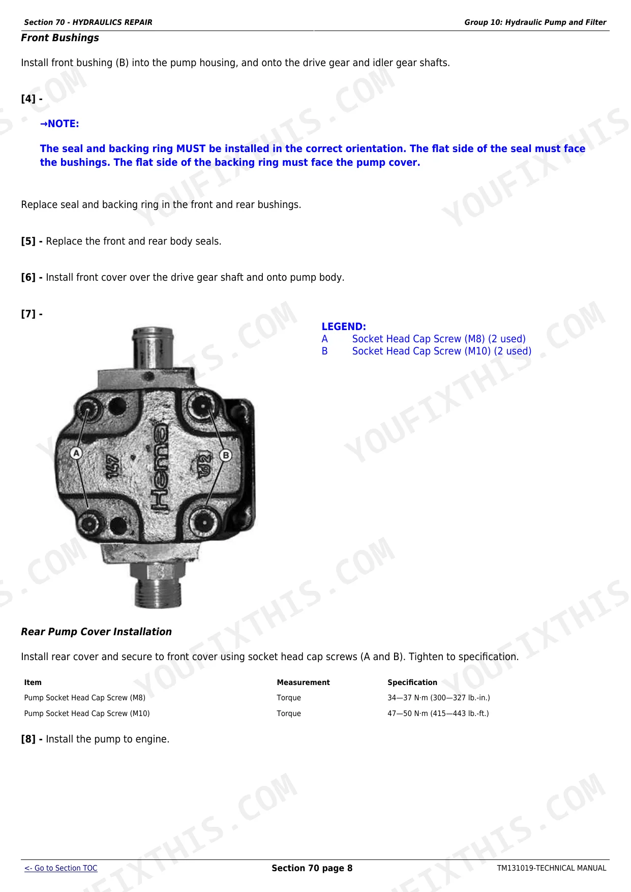
Worn pump seals and a clogged hydraulic filter are the primary culprits after 1,500 hours. Follow the hydraulic pump and filter removal and inspection steps in Section 70 to pull and inspect the pump seal kit. Section 270 gives the hydraulic pressure test procedure and minimum pressure spec so you can confirm whether the pump is at fault or the problem is internal cylinder leakage before committing to a rebuild.
Manual Section: Hydraulics Repair (Section 70) / Hydraulics Operation and Tests (Section 270)Hydrostatic transmission slips in gear or will not engage during PTO work
On 4049R and 4052R models, clutch plate wear and internal gear contamination are the frequent causes of slip under PTO load. Pull the PTH fault codes from the instrument cluster using the procedure in Section 211, then follow the PTH diagnostic routine in Section 250 which covers calibration checks and pressure testing of the hydrostatic circuit. The theory of operation in Section 250 identifies whether the fault is in the variable-displacement pump, the control valve, or the PTH control unit - narrowing the repair before splitting the machine.
Manual Section: Transmissions Repair (Section 50) / Power Train Diagnostics (Section 250)Engine overheats - coolant temperature warning during field work
Debris in the radiator fins is the most common cause on tractors working in dusty conditions. Section 20 covers radiator removal, inspection, and cleaning procedure: remove the grille, disconnect the hoses, and clean the fins with compressed air directed parallel to the fins to avoid bending them. Also inspect the thermostat and coolant pump O-ring (see CTM 120419 referenced in Section 20) and verify coolant capacity - open-station models hold only 6.0 L, so even a minor seep can drop the level enough to trigger overheating under load.
Manual Section: Engine Repair (Section 20)Frequently Asked Questions
What diagnostic trouble codes are covered in the John Deere 4044M/4066R diagnostic manual?
The manual covers ECU (Engine Control Unit), ICC (Instrument Cluster Control), PTH (Hydrostatic Power Train), and PTR (Power Train Reverser) fault codes. Section 211 lists each code with its description, and Sections 212 and 245 walk you through the diagnostic routines step by step so you can isolate the failed component before ordering parts.
How do you diagnose a hydrostatic transmission fault on the John Deere 4044M or 4066R?
Start in Section 211 to pull the PTH code from the instrument cluster, then go to Section 250 for the PTH theory of operation and the step-by-step diagnostic routine. The manual provides the calibration procedure, schematics, and pressure test specs so you can tell whether the fault is in the hydrostatic pump, the control valve, or the PTH control unit before pulling the transmission.
What are the engine torque specs for the John Deere 4052M/4052R?
Section 20 of TM131019 calls out the key values directly in the repair procedures: flywheel cap screws 86 N.m (63 lb-ft), connecting rod cap screws 49 N.m (36 lb-ft), main bearing cap screws 98 N.m (72 lb-ft), and crankshaft pulley cap screw 117 N.m (86 lb-ft). Every fastener-critical step in the engine section lists the spec inline.
Does the TM131019 cover the hydraulic system schematics and pressure test procedures?
Yes. Section 270 covers hydraulics operation, theory of operation, full system schematics, and pressure tests and adjustments. Section 70 covers the hydraulic pump and filter, rockshaft, range control and three-point hitch, and selective control valve removal and installation. Hydraulic connector identification is cross-referenced in Section 279.
What are the fuel and hydraulic fluid capacities for the John Deere 4044M/4066R series?
The open-station models hold 49.2 L (13.0 gal.) of fuel and the cab models hold 52 L (13.8 gal.). The hydraulic reservoir is 47.3 L (12.5 gal.) across all variants. Coolant capacity is 6.0 L (1.6 gal.) on open-station tractors and 8.0 L (2.1 gal.) on cab models. These specs are listed in Section 20 within the engine removal and coolant drain steps.
Is this John Deere 4044M, 4044R, 4049M, 4049R, 4052M, 4052R, 4066M, 4066R?
You get a 2285-page searchable PDF (106 MB) that downloads instantly after checkout. Open it on your laptop, tablet, or phone, and bring it right to the shop floor.
Am I able to print pages from this John Deere 4044M, 4044R, 4049M, 4049R?
Zero restrictions. The PDF is DRM-free. Print whatever sections you need to take out to the shop. Standard letter or A4 paper works.