


Part of the John Deere Repair Manuals.
This is the complete John Deere factory repair manual (TM4566) for the 6810, 6910 and 6910S tractors. Across 1,860 pages it covers every system on these machines: the 4045/6068 diesel engine at full depth, three transmission variants (Power Shift, AutoPowr, PowrQuad/AutoQuad), the full hydraulic system including the rockshaft and selective control valves, steering and brakes, and the entire electrical system with wiring harnesses and connector repair. It is the same reference a John Deere dealer technician works from, with the torque values, capacities and test pressures printed so the repair is done to spec the first time.
What's Inside This John Deere 6810, 6910, 6910S Repair Manual
| System | Pages | Key Topics |
|---|---|---|
| Safety | - | |
| General Information | Specifications, Tune-Up, Predelivery Inspection | |
| Engine | Engine Removal and Installation | |
| Fuel, Air Intake, Cooling and Exhaust Systems | Speed Control Linkage, Fuel System, Air Intake System, Cooling System, Cold Weather Starting Aids, Exhaust System | |
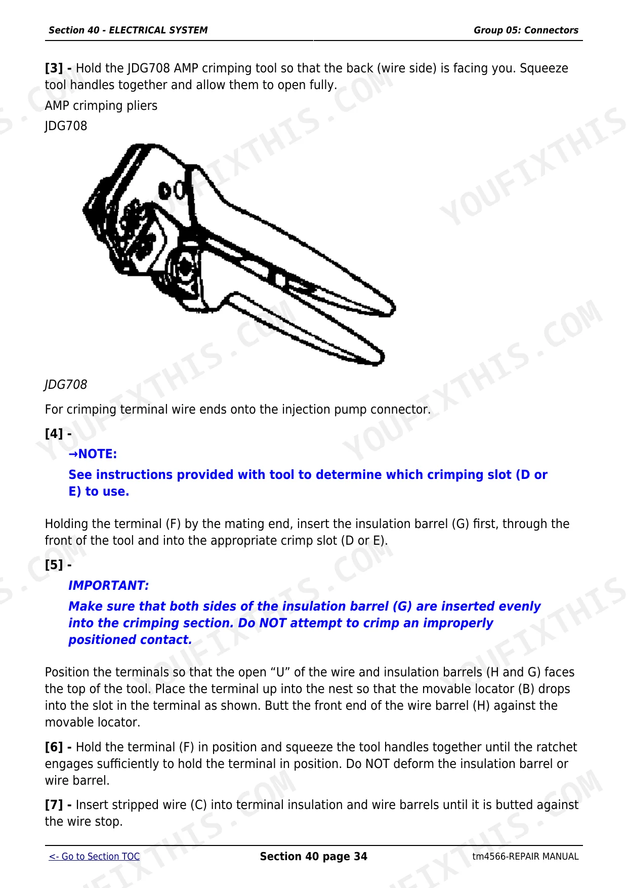
| Electrical System | Connectors, Wiring Harnesses, Charging Circuit, Starter Motor Circuit, Fuses, Relays and Switches, Monitoring Systems, Electrical Components | |
| Power Shift Transmission | Removing and Installing Power Shift Transmission, Shift Controls, Reduction Gearbox | |
| AutoPowr Transmission | Removing and Installing AutoPowr Transmission, Transmission Shift Controls, Input Housing, Output Housing, Differential Drive Shaft | |
| PowrQuad, PowrQuad Plus and AutoQuad Transmissions | Removal and Installation, Transmission Shift Controls, PowrQuad Module, Creeper Transmission, Range Transmission | |
| Drive Systems | U-Jointed Shafts and Torsion Damper, Front-Wheel Drive Clutch, Differential, Hydraulic Pump Drive, Final Drives, Rear PTO Options, Front PTO, Front Implement Drive | |
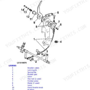
| Steering and Brakes | Hydrostatic Steering, Brake Valve (Power Fill Brakes), Brake Valve (with MFWD and Disk Brake), Rear Brakes, Handbrake, Hydraulic Trailer Brake, Air Brakes | |
| Hydraulic System | Controls, Hydraulic Pump and Charge Oil Pump, Valves, Rockshaft and Rockshaft Cylinder, Three-Point Hitch, Selective Control Valves and Couplers, Independent Control Valve | |
| Miscellaneous | Main Frame, Front and Rear Wheels, Trailer Hitch and Swinging Drawbar, Triple Link Suspension of FWD Axle, Pick-Up Hitch | |
| Operator's Cab | Tilting and Removing the Cab, Controls and Instruments, Electronic Hitch Control Components, Air Conditioning System, Heating System, Seats, Radio Installation Components | |
| Special Tools (Dealer-Fabricated) | - |
Quick Reference Specifications
| Specification | Value | Page |
|---|---|---|
| 6810, 6910, 6910S | ||
| Engine models | John Deere 4045 / 6068 diesel | |
| All models | ||
| Rated engine speed | 2100 rpm | |
| Fast idle (electronic actuation) | 2250 rpm (-10 / +20 rpm) | |
| Engine oil capacity | approx. 17 L (4.5 US gal.) | |
| Coolant capacity | approx. 15.5 L (4.1 US gal.) | |
| Radiator cap pressure valve (opens at) | 70 to 90 kPa (0.70 to 0.90 bar; 10 to 13 psi) | |
| Cooling system test pressure | 50 to 60 kPa (0.5 to 0.6 bar; 7 to 8.7 psi) | |
| All models with cab A/C | ||
| A/C refrigerant (R134a) capacity | 1.3 kg (2.86 lb) | |
| Tractor | ||
| Permissible total weight | 5244 kg | |
John Deere 6810, 6910, 6910S Common Problems This Manual Covers
Fuel system over-pressurizing or acting like it is losing rail pressure at high hours
Test the fuel lift pump output pressure as described in the Fuel System section and check for debris in the tank pickup. Replace the rail pressure sensor if the pump output is within spec but the ECU reads a pressure fault - owners with 6910s at very high hours report the sensor fails before the pump. Clearing the tank of sediment and fitting a new lift pump stops most recurrences on machines above 40,000 hours.
Manual Section: Fuel, Air Intake, Cooling and Exhaust SystemsHead gasket failure, typically between 8,000 and 10,500 hours under sustained heavy load
Follow the Engine section's head removal and refitting sequence. Replace the gasket with the OEM part, torque the head bolts to the factory sequence in the General Information specifications, then refill and bleed the cooling system per the Cooling System section. Running the tractor at moderate load for the first few hours lets the new gasket seat before returning to full demand.
Manual Section: EngineRear linkage cross shaft showing play or spline wear after approximately 8,000 hours
The rear linkage cross shaft splines wear progressively on 6810 and 6910 machines used for heavy lifting work. The Drive Systems section covers removing the rear PTO and linkage components and inspecting shaft spline condition. Catch it early - once the splines are badly worn the shaft and arm both need replacement, while catching it at first signs of play lets you fit just a new shaft.
Manual Section: Hydraulic SystemTransmission or hydraulic oil level dropping below sight-glass marks without an obvious leak
Check the hydraulic pump seals and the filter housing O-rings before assuming internal wear. A slow weep past a pump seal or a cracked filter housing O-ring drains the system gradually and is often missed during routine checks. The Hydraulic System section covers removing and resealing the hydraulic pump and charge oil pump so you can confirm the source without disassembling the full transmission.
Manual Section: Hydraulic SystemFrequently Asked Questions
What engines are fitted to the John Deere 6810, 6910 and 6910S tractors?
All three models run John Deere four- or six-cylinder turbocharged diesels - the 4045 or 6068 series depending on specification. Rated engine speed is 2100 rpm and the crankcase takes approximately 17 L (4.5 US gal.) of oil. The manual covers the full engine removal, rebuild and reinstallation procedure for both engine families.
Why does the 6910 keep over-pressurizing the fuel system or acting like it is losing rail pressure?
Owners with high-hour machines (some at 50,000 hours) report this pattern comes from a failing rail pressure sensor, a worn fuel lift pump, or debris in the fuel tank blocking the pickup. The Fuel System section covers testing the lift pump output pressure and replacing the rail pressure sensor so you can identify whether the fault is the sensor reading or actual mechanical pressure loss before ordering parts.
Which transmission variants does TM4566 cover?
The manual covers three transmissions fitted to the 6x10 series: the Power Shift (Section 52), the AutoPowr continuously variable transmission (Section 53), and the PowrQuad, PowrQuad Plus and AutoQuad powershift-on-the-go units (Section 55). Each section includes removal, disassembly, component inspection and reinstallation procedures so you can work on any variant fitted to your machine.
How do I check and maintain the transmission and hydraulic oil on a 6810 or 6910?
The oil level must read between the sight-glass marks on the reservoir. Low levels often trace to a slow leak rather than consumption, so inspect the hydraulic pump seals and filter housing. The Hydraulic System section covers removing and inspecting the hydraulic pump and charge oil pump, and the Drive Systems section has the final-drive oil service intervals and capacities.
Does this manual cover the head gasket replacement procedure on the 6810 or 6910?
Yes. The Engine section covers the full top-end strip, head removal, gasket replacement and torquing sequence. Head gasket failure is a known weak point on high-hour 6x10 machines, typically appearing after 8,000 to 10,000 hours under sustained heavy load. The manual gives the tightening sequence, coolant refill procedure and bleed steps so the job is done correctly the first time.
How will I receive this John Deere 6810, 6910, 6910S Repair?
Immediate download of the complete 1860-page searchable Repair (33 MB). Access it on any device, from a laptop at your desk to a phone in the field.
Am I able to print pages from this John Deere 6810, 6910, 6910S manual?
No restrictions at all. Print individual pages, full chapters, or the entire manual. The PDF is completely unlocked.


Reviews
There are no reviews yet.