
Part of the John Deere Repair Manuals.
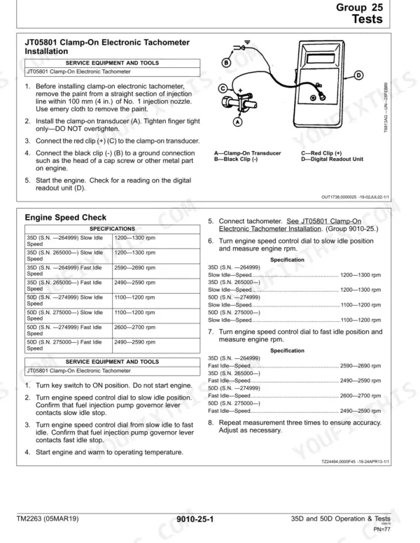
All 682 pages of this John Deere 35D Technical Manual (OEM TM2263) cover one pair of machines: the 35D and 50D mini excavators, from engine to undercarriage. Inside you get complete wiring diagrams for every harness on both models, from the Main Harness (W8) through the Cab, Engine, and A/C Compressor harnesses, each paired with component location diagrams and a master legend. You also get full hydraulic schematics covering the 35D and 50D separately, pilot system diagrams, and a structured troubleshooting section stepping through dig circuit faults, swing malfunctions, and travel system failures. Set engine valve lash to 0.15–0.25 mm cold, hold battery voltage between 10 and 14 volts, and cap cooling system pressure at 90 kPa. No more forum guesses when the machine sits dead. Bookmarked and searchable; pull up any spec by keyword and get back to wrenching.
What's Inside This John Deere 35D, 50D Manual
| System | Pages | Key Topics |
|---|---|---|
| General Information | 7-22 | Group 01 |
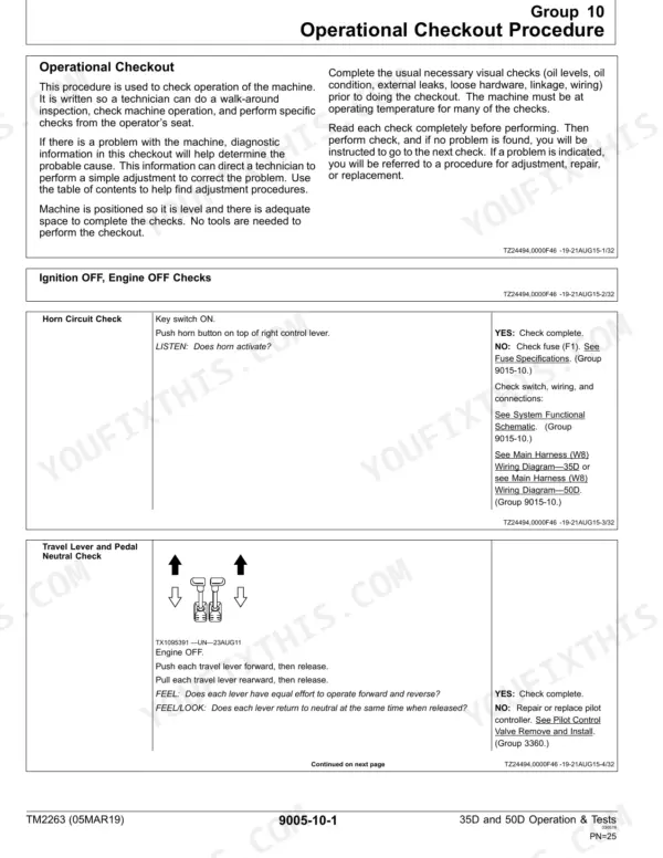
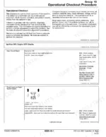
| Operational Checkout Procedure | 23-50 | Group 10, Operational Checkout Procedure (Ignition Off, Engine Off Checks, Ignition on, Engine on Checks), Operational Checkout, Ignition Off |
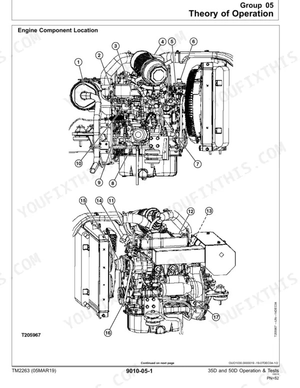
| Engine | 51-99 | Group 05, Theory of Operation (Engine Component Location, Cooling System, Engine Lubrication System, Engine Fuel System Operation), Group 15 |
| Electrical Diagram Information | 101 | Explanation of Wire Markings |
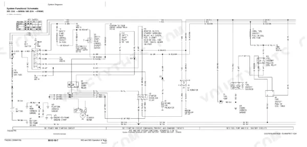
| System Functional Schematic Diagram | 102 | Key Switch, Battery, Starter Motor, Alternator, Fuses, Relays |
| System Functional Schematic | 103 | Power Supply, Ground Wires, Component Identification, Continuity Chart, Routing Location Information |
| Wiring Diagram | 104 | Splice Identification Number, Connector Pin Legend, Wire Number, Wire Color, Harness Branch, Connector End View |
| Component Location Diagram | 105-106 | Electrical Components, Connectors, Harness Main Ground Locations, Harness Band, Clamp Location |
| Electrical Schematic Symbols | 107-108 | Battery, Fuse, Relay, Switch, Motor, Sensor |
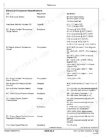
| Fuse (Blade-Type) Color Codes | 109-110 | Amperage Rating, Color |
| Fuse Specifications | 111 | Horn, Monitor, Safety Start, Work Lights, Travel Speed Selector, Glow Plug |
| System Functional Schematic, Wiring Diagrams, and Component Locations Master Legend | 112-432 | Fuel Shutoff Pull-In Coil Timer, Monitor Controller and Display, Auto-Idle Controller, Travel Alarm Controller, Heating and Air Conditioner Controller, Fuel Level Sensor |
| Power Train | 433-445 | Group 05, Theory of Operation (Track Adjuster and Recoil Spring, Travel Gearbox Operation), Group 15 |
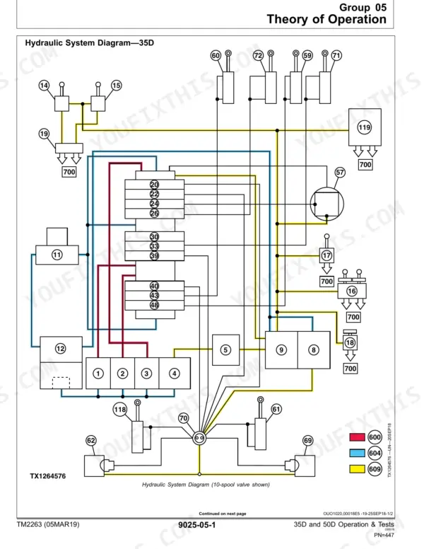
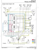
| Hydraulic System | 446 | Group 05 |
| Heating and Air Conditioning | 655-670 | Group 05, Theory of Operation (Air Conditioning System Cycle of Operation), Group 15 |
Quick Reference Specifications
| Specification | Value | Page |
|---|---|---|
| All Models | ||
| Battery Voltage | 10—14 volts | p. 414 |
| Engine Valve Lash (cold) Clearance | 0.15—0.25 mm | p. 83 |
| Air Intake System Pressure | 14—21 kPa | p. 91 |
| Cooling System Maximum Pressure | 90 kPa | p. 92 |
| Engine Compression Pressure | 3324—3530 kPa | p. 94 |
| Engine Oil Pressure at Fast Idle | 296 kPa | p. 95 |
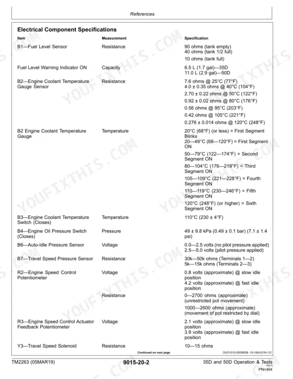
| Fuel Level Sensor Resistance (tank empty) | 90 ohms | p. 404 |
| Engine Coolant Temperature Switch (Closes) Temperature | 110°C | p. 404 |
| Travel Speed Solenoid Resistance | 10—15 ohms | p. 404 |
| 35D | ||
| Pilot Pressure Regulating Valve at Fast Idle, 35D | 3900—4900 kPa | p. 627 |
| 50D | ||
| Pilot Pressure Regulating Valve at Fast Idle, 50D | 6100—7100 kPa | p. 627 |
John Deere 35D, 50D Common Problems This Manual Covers
No hydraulic movement after engine starts, all boom and stick controls are dead
Confirm the pilot control shutoff lever is fully lowered (UNLOCKED); page 381 explains how fuse F3 energizes solenoid Y4, allowing pilot pressure to reach the controllers. If lever position is correct, measure pilot pressure at fast idle: 3900-4900 kPa on the 35D, or 6100-7100 kPa on the 50D (page 627). A reading below spec points to the pilot relief valve.
Manual Section: Diagnose Pilot Circuit Malfunctions p. 381Engine overheats during normal digging, coolant temperature warning triggers within an hour
Pressure-test the cooling system; maximum pressure is 90 kPa (page 92). Check coolant level and inspect the radiator screen for debris blocking airflow. Verify the cooling fan blade is intact. Check the engine coolant temperature switch: it should close at 110°C (page 404). Persistent overheating after those checks points to a failed thermostat or oil cooler core blockage.
Manual Section: Engine Overheats Diagnostics Procedure p. 92Boom or stick drifts down slowly in neutral, attachment won't hold position when stopped
Test boom cylinder drift with a 165 kg bucket load (page 625); maximum allowable is 5 mm over 5 minutes (page 625). If drift exceeds the limit, inspect the dig circuit starting and check pilot pressure at page 627. Excessive drift with normal pilot pressure isolates the fault to the control valve spool or cylinder seals.
Manual Section: Diagnose Dig Circuit Malfunctions p. 625Frequently Asked Questions
How to reset hydraulic pilot lock on John Deere 35D?
To reset the hydraulic pilot lock on the John Deere 35D, move the left armrest/pilot shutoff lever to the UNLOCKED (lowered) position. This action closes the contacts of the safety start pilot control shutoff switch, energizing the pilot control shutoff solenoid (Y4) and allowing hydraulic pilot pressure to flow to all pilot controllers. For more information on the pilot control shutoff circuit, see Starting Circuit Theory of Operation. (Group 9015-15.) p. 381
What are the replacement specifications for Fuel shutoff solenoid?
The replacement specification for the Fuel Shutoff Solenoid (Y4) is a resistance of 10–15 ohms. If the solenoid does not produce the specified resistance after testing, it should be replaced. For detailed testing procedures, refer to the Solenoid Test on page 409. p. 405
How do you fix john Deere 35D excavator won't start, dashboard powers up but no buzzer and engine won't crank?
Check battery voltage at the terminals; it must read 10-14 volts (page 414) before chasing deeper electrical faults. Inspect blade-type fuses next, referencing the Safety Start and Monitor fuse ratings on page 111. Clean all harness ground locations shown on page 105. Corroded terminals or an open Safety Start fuse account for most silent-no-crank failures. p. 414
How do you fix engine dies mid-shift after several hours running, restarts briefly then quits again?
Inspect the fuel shutoff solenoid circuit for intermittent voltage drop and check connections at the fuse block (page 111). Verify no air is entering fuel lines; bleed and retighten all fittings. Test engine compression when cold: spec is 3324-3530 kPa (page 94). If compression is good, suspect a failing solenoid or cracked fuel return line. p. 94
Is this John Deere 35D Technical Manual a digital download?
This is a 682-page searchable PDF ready for immediate download. Works on any device, so pull it up on your phone while you're under the hood. No shipping, no waiting.
Am I able to print pages from this John Deere 35D manual?
Yes. Print individual pages or full chapters for your own shop use, on letter or A4 paper.
Can I find wiring schematics in this John Deere 35D manual?
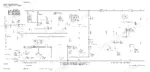
A wiring diagram for the John Deere 35D, 50D Excavator electrical system is included.







Reviews
There are no reviews yet.