
Part of the John Deere Repair Manuals.
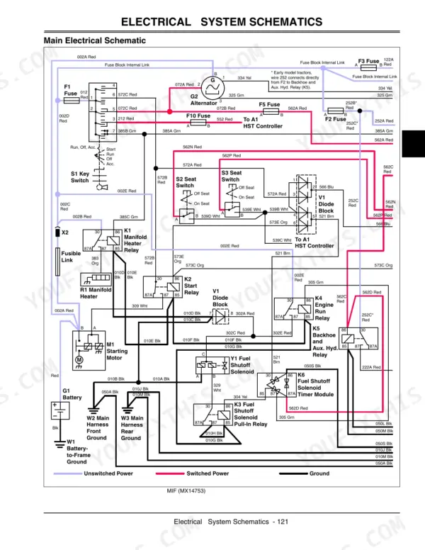
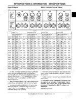
This 540-page John Deere 110 Tractor Loader Backhoe Technical Manual (OEM #TM1987 JUN02) puts the complete engine, electrical, power train, hydraulics, steering, brakes, loader, and backhoe repair reference in your hands. Open it and you get full wiring harness color codes with schematics for every circuit (charging, cranking, PTO, HST control), plus main hydraulic schematics covering the loader valve, backhoe valve, and rockshaft circuits. You'll also find test-and-adjustment procedures for cylinder compression, valve clearance, and HST calibration, right down to the fastener specs: torque that M10 Grade 7 bolt to 52 N-m into steel, or 41 N-m into aluminum, and set your HST potentiometer test input at 5.0 ± 0.2 volts. No more chasing an HST fault code with a multimeter and a guess. This PDF carries full bookmarks, so you jump straight from the index to the exact backhoe or hydraulic section your 110 needs, right there on the shop floor.
What's Inside This John Deere 110 Manual
| System | Pages | Key Topics |
|---|---|---|
| Introduction | 3-4 | Manual Description (Table of Contents, Specifications and Information, Engine-Diesel, Electrical, Power Train, Hydraulics, Steering, Brakes, Loader, Backhoe, Miscellaneous) |
| Safety | 5-10 | Recognize Safety Information, Understand Signal Words, Replace Safety Signs, Be Prepared for Emergencies |
| Specifications & Information | 11-28 | Table of Contents (Specifications, Metric Fastener Torque Values, Metric Fastener Torque Values - Grade 7, Inch Fastener Torque Values, Face Seal Fittings with Inch Stud Ends Torque, Face Seal Fittings with Metric Stud Ends Torque, O-Ring Face Seal Fittings, O-Ring Boss Fittings, Diesel Fuel, Diesel Fuel Lubricity, Diesel Fuel Storage, Dieselscan™ Fuel Analysis, Engine Oil, Engine Break-In Oil, Oilscan®, Oilscan Plus®, Coolscan™, And Coolscan Plus™, Alternative Lubricants, Synthetic Lubricants, Lubricant Storage, Mixing of Lubricants, Chassis Grease, Transaxle Oil, Engine Coolant, Testing Diesel Engine Coolant, Operating in Warm Temperature Climates, Flush and Service Cooling System, Disposing of Coolant, Engine Coolant Drain Interval, Machine Product Identification Number, Engine Serial Number Location, Interlock System) |
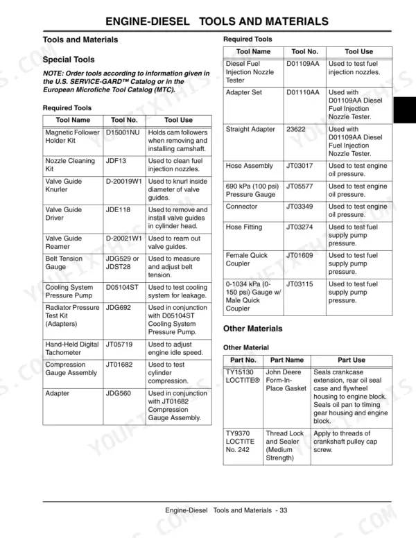
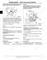
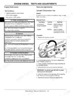
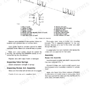
| Engine-Diesel | 29-110 | Specifications (Repair Specifications, Tests and Adjustment Specifications, Torque Values, Non-Standard Fasteners), Tools and Materials (Special Tools, Other Materials) |
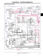
| Electrical | 111-270 | Air Filter Restriction Light, Alternator, Battery, Charging Circuit, Cranking Circuit, HST Control System |
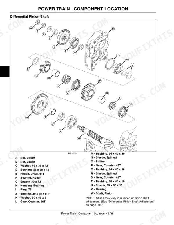
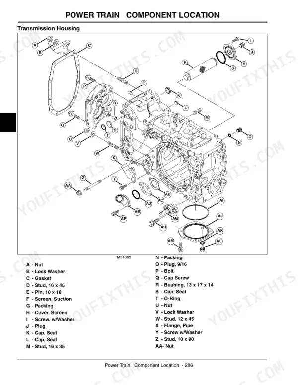
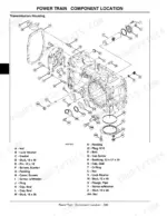
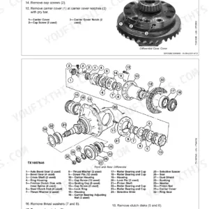
| Power Train | 271-364 | Specifications (Test and Adjustment Specifications, HST Repair Specifications, Final Drive Repair Specifications), Tools and Materials (Special or Essential Tools, Other Materials) |
| Hydraulics | 365-466 | Specifications (Test and Adjustment Specifications, Repair Specifications), Tools and Materials (Special or Essential Tools, Other Materials) |
| Steering | 467-478 | Steering Specifications, Steering Component Location, Steering System Schematic, Steering System Leakage Test, Steering Pump Pressure Test, Toe-In Adjustment |
| Brakes | 479-492 | Specifications (Brakes), Component Location (Brake Pedals and Linkage, Brake Housing, Park Brake), Theory of Operation (Brakes), Diagnostics (Brake System Diagnosis) |
| Loader | 493-502 | Repair Specifications, Loader Component Location, Loader Removal/Installation, Boom Repair, Quik-Tatch® Attachment Plate Removal/installation |
| Backhoe | 503-518 | Repair Specifications, Backhoe Components, Bucket and Bucket Link Removal/Installation, Backhoe Control Valve Linkage Removal/Installation, Dipperstick Removal/Installation |
| Miscellaneous | 519-532 | Table of Contents (Specifications, Repair Specifications, Repair, Seat and Seat Support Removal/Installation, Seat Closeout Panel Removal/Installation, Rear Fender Removal/Installation, Loader Joystick Removal/Installation, Fuel Tank Removal/Installation, Roll Over Protection System Removal/Installation, Front Wheel Removal/Installation, Rear Wheel Removal/Installation, Operator’s Platform Removal/Installation) |
Quick Reference Specifications
| Specification | Value | Page |
|---|---|---|
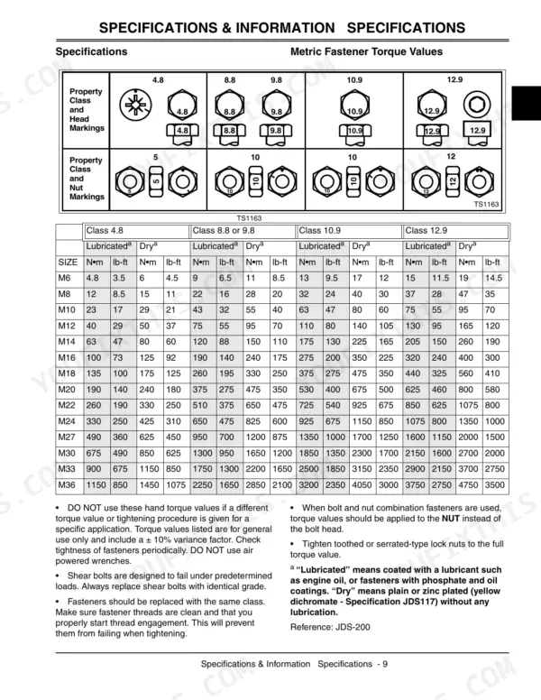
| Metric Fastener Torque Values - Grade 7, M10, Steel or Gray Iron Torque | 52 (38) N•m (lb-ft) | p. 14 |
| Metric Fastener Torque Values - Grade 7, M10, Aluminum Torque | 41 (30) N•m (lb-ft) | p. 14 |
| HST Forward and Reverse Pedal Potentiometer Test Input Voltage | 5.0 ± 0.2 volts | p. 258 |
| Engine Oil Capacity (Approximate) | 4.9 L | p. 31 |
| Cooling Capacity (Approximate) | 8.7 L | p. 31 |
| Slow Idle Speed | 1050 rpm | p. 31 |
| High Idle (No Load) | 2800 rpm | p. 31 |
| Cylinder Head Bolt Torque (Lubricating Oil Applied) | 85-91 N•m | p. 36 |
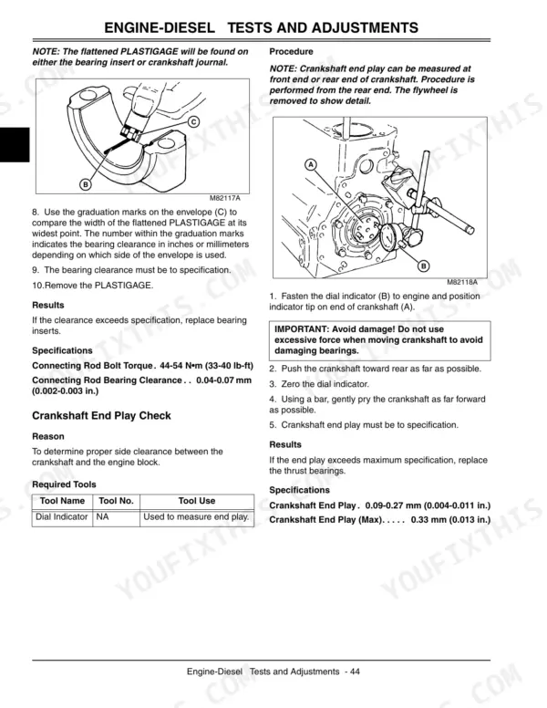
| Connecting Rod Bolt Torque (Lubricating Oil Applied) | 44-54 N•m | p. 36 |
| Main Bearing Bolts (Lubricating Oil Applied) | 96-100 N•m | p. 36 |
| Battery Voltage | 12VDC | p. 113 |
John Deere 110 Common Problems This Manual Covers
John Deere 110 TLB hydraulic functions fade after use with loud pump noise and no cylinder response.
Inspect the hydraulic suction hose and manifold for deterioration causing pump aeration. Drain the system and replace any damaged hoses. When reinstalling hydraulic components on page 427, torque the relief valve to 45 N•m (33 lb-ft). Refill the fluid and test loader operation to confirm the noise is gone.
Manual Section: Hydraulics Repair p. 427Forward or reverse drive surges and creates an erratic on and off motion during smooth travel.
Test the HST forward and reverse pedal potentiometer input voltage on page 258. Verify the sensor reads exactly 5.0 ± 0.2 volts. Replace the potentiometer if out of spec. Inspect the pedal linkage for wear or binding and lubricate pivot points to ensure smooth directional control.
Manual Section: Electrical Circuit Operation and Diagnosis p. 258Loose loader mast and frame bolts create heavy stress concentrations and cracked bell or transmission housings.
Inspect the bell housing for hairline cracks. Remove the loader frame bolts and check the mounting holes for elongation. Replace damaged hardware and tighten the M10 steel bolts to 52 N•m (38 lb-ft) as noted on page 14. Weld or replace the housing if cracked and retest.
Manual Section: Loader Repair p. 14Electrical starting circuit faults create a sudden no crank and no start condition.
Test the battery voltage to ensure it reads a minimum of 12VDC as specified on page 113. Inspect the battery cables for corrosion and clean the terminal connections. Check the standard alternator rating of 40 amps to confirm charging system health before replacing the main starting relay.
Manual Section: Electrical Circuit Operation and Diagnosis p. 113Frequently Asked Questions
What is the meaning of the John Deere 110 error code '• - • •'?
The flash sequence '• - • •' on the HST status light indicates a problem with the Forward Pedal Potentiometer. This means the voltage signal is out of range or the input is not calibrated, leading to no drive in either direction. The recommended action is to get the signal in range and recalibrate the potentiometer. p. 145
What error code indicates that the John Deere 110 won't move?
If the John Deere 110 won't move and the HST status light flashes '• - • •', it indicates a problem with the Forward Pedal Potentiometer. This issue, where the voltage signal is out of range or input is not calibrated, results in no drive in either direction. The solution involves getting the signal in range and recalibrating the potentiometer. p. 145
How do I reset the hydraulic code on a John Deere 110?
For HST control system service codes, such as those related to potentiometers, the reset action involves cycling controller power to clear the code after ensuring the signal is back in range or recalibrating the potentiometer. For example, after correcting a Forward Pedal Potentiometer issue, cycle controller power to clear the code. p. 145
How do I reset the John Deere 110 HST control system to factory specifications?
To reset the HST control system to factory specifications, enter the automatic calibration mode by moving the 10-amp fuse from the F11 (storage) position to the F12 socket with the key switch in OFF position. This process resets all controller values to zero, so the calibration procedure must be completed before driving the tractor. p. 265
What are the general torque specifications for M10 metric fasteners on the John Deere 110?
For M10 metric fasteners on the John Deere 110, the lubricated torque value is 43 N•m (32 lb-ft) and the dry torque value is 55 N•m (40 lb-ft). These values are for general use and include a ± 10% variance factor. p. 13
What do I get after purchasing this John Deere 110?
You get a 540-page searchable PDF that downloads instantly after checkout. Open it on your laptop, tablet, or phone, and bring it right to the shop floor.
Am I free to print this John Deere 110 Technical Manual?
Yes. Print the pages or sections you need for your own shop use. Any standard printer works.








Reviews
There are no reviews yet.