


![John Deere 330CLC 370C Repair Manual [Excavator]](https://youfixthis.com/wp-content/uploads/2012/02/Manual_Download-300x300.jpg)
Part of the John Deere Repair Manuals.
Need the factory teardown procedures for your John Deere 250D, 300D Articulated Dump Trucks? All 560 pages of this repair manual (OEM #TM2116) walk through every major system: axles and suspension, transmission and transfer drive, steering, service and park brakes, main hydraulic circuits, pneumatic systems, and body lift. Inside you get hydraulic schematics showing complete fluid routing through the main pump and manifold assembly, page after page of torque specifications, full exploded views of drivetrain components, and step-by-step procedures from differential rebuilds to transfer case alignment. Torque the hydraulic manifold tie bolt nut to 80 N·m (59 lb-ft); for the body lift cylinder, the piston-to-rod nut goes to 500-550 N·m (369-406 lb-ft). Your truck is parked and the clock is running. One download, bookmarked by section, opens on any device. Bring it right to the machine and start wrenching.
What's Inside This John Deere 250D, 300D Repair Manual
| System | Pages | Key Topics |
|---|---|---|
| General Information | 7-18 | Recognize Safety Information, Follow Safety Instructions, Operate Only If Qualified, Wear Protective Equipment, Avoid Unauthorized Machine Modifications, Inspect Machine |
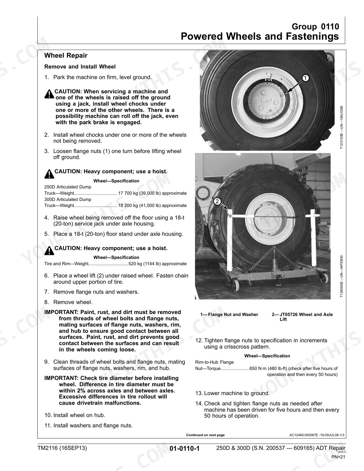
| Wheels | 19-24 | Wheel Repair, Remove and Install Wheel, Disassemble and Assemble Wheel, Inflate Tire |
| Axles and Suspension Systems | 25-146 | Group 0200 |
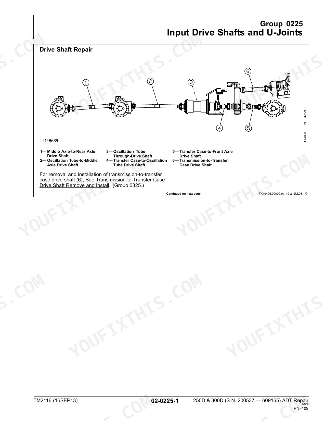
| Transmission | 147-280 | Group 0300, Removal and Installation (Engine and Transmission Remove), Group 0325, Input Drive Shafts and U-Joints (Transmission-to-Transfer Case Drive Shaft Remove and Install) |
| Engine | 281-296 | Engine Repair (Mount Engine on Repair Stand), 250D and 350D Crankshaft Damper Removal Procedure, Torque Wrench Adapter Torque Calculation |
| Engine Auxiliary System | 297-314 | Group 0510, Cooling System (Fan Belt Repair, Radiator Repair), Group 0520, Intake System (Air Intake System Leakage Check, Charge Air Aftercooler Repair), Group 0530 |
| Connector Drive (Flexplate) | 315-318 | Connector Drive Repair, Remove Connector Drive, Install Connector Drive |
| Transfer Drive | 319-368 | Transfer Case Remove, Transfer Case Install, Transfer Case Alignment, Drive Shaft Alignment, Transfer Case Housing Disassemble, Transfer Case Housing Assemble |
| Steering System | 369-386 | Secondary Steering Pump Repair, Steering Valve Remove and Install, Steering Valve Disassemble and Assemble, Steering Cylinder Repair |
| Service Brakes | 387-398 | Service Brake Bleed System, Service Brake Pad Repair, Service Brake Caliper Repair, Service Brake Disk Repair, Brake Valve Repair, Brake Accumulator Repair |
| Park Brake | 399-404 | Park Brake Repair, Remove and Install Park Brake Pads, Remove and Install Park Brake Caliper, Remove and Install Park Brake Disk |
| Frame and Supporting Structure | 405-426 | Welding on Machine, Front and Rear Frame Separation, Articulation Frame Repair, Oscillation Joint Bushings Inspect, Oscillation Joint Sleeves Remove and Install |
| Operator's Station | 427-468 | Group 1810, Operator Enclosure (Cab Remove and Install, Cab Mount Repair, Cab Tilt Pump and Cylinder Repair, Windowpanes Remove and Install, Cab Door Window Installation) |
| Sheet Metal and Styling | 469-476 | Hood Repair, Remove and Install Hood, Adjust Hood, Adjust Latch Linkage, Adjust Stoppers |
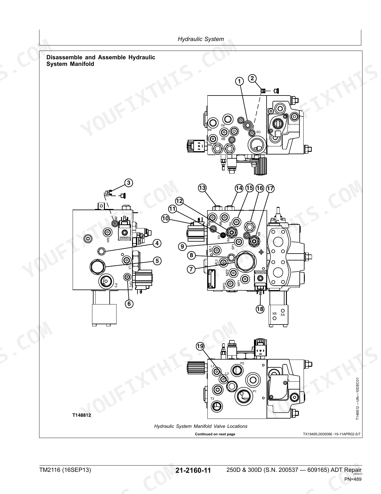
| Main Hydraulic System | 477-492 | Main Hydraulic Pump Repair, Hydraulic Reservoir Repair, Hydraulic Suction Strainer Repair, Hydraulic System Manifold Assembly Repair |
| Pneumatic Systems | 493-510 | Group 2261, Pumps and Drives (Air Compressor: Repair, Drive Gear Repair), Group 2262 |
| Haulage Device | 511 | Body Repair (Remove and Install Body, Align Body) |
| Dealer Fabricated Tools | 6 | DFT1132 Removal and Installation Tool, DFT1178 Lifting Tool, DFT1182 Transfer Case Mounting Bracket, DFT1183 Rolling Drag Torque Bar, DFT1197 Front Support |
Quick Reference Specifications
| Specification | Value | Page |
|---|---|---|
| All Models | ||
| Piston-to-Rod Nut—Torque | 500—550 N·m (369—406 lb-ft) | p. 521 |
| Rod Guide-to-Cylinder Barrel Socket Head Cap Screw—Torque | 145 N·m (107 lb-ft) | p. 521 |
| Oil Filter Cover—Torque | 23 N·m (204 lb-in.) | p. 265 |
| Hydraulic System Manifold Assembly Tie Bolt Nut—Torque | 80 N·m (59 lb-ft) | p. 485 |
| Dump Body Control Valve Seal and O-ring Replacement | Replace all seals and O-rings. | p. 486 |
| Wheel Rim-to-Hub Flange Nut Torque | 650 N·m (480 lb-ft) | p. 21 |
| Front Axle Weight | 1111 kg (2450 lb) | p. 27 |
| Front and Rear Differential Pinion Nut Torque | 750 N·m (553 lb-ft) | p. 45 |
| Transmission Weight | 345 kg (760 lb) | p. 149 |
| Engine and Transmission Weight | 1179 kg (2600 lb) | p. 287 |
| 250D | ||
| Middle Axle Weight | 930 kg (2050 lb) | p. 30 |
| 300D | ||
| Middle Axle Weight | 1066 kg (2350 lb) | p. 30 |
John Deere 250D, 300D Common Problems This Manual Covers
Dump body pivot hinge bushings worn, excessive play or clunking at body pins
Inspect all dump body pivot points for wear and measure bushing clearance. Press new bushings into both head end and rod end locations per Section 35. The body lift cylinder weighs 191 kg (420 lb) (page 518); support it fully before unbolting. Grease all pivot points at reinstallation and verify free dump body movement through a full raise-lower cycle.
Manual Section: Haulage Device p. 518Service brake pads worn thin, pedal travel excessive or grinding noise on stops
Measure pad thickness; replace any pad worn to 2.0 mm (0.08 in.) or less, per the spec on page 389. Remove the caliper following Service Brake Pad Repair procedures and inspect the disk surface for scoring. After fitting new pads, bleed the brake system and verify pedal feel through several firm stops before returning the machine to full haul duty.
Manual Section: Service Brakes p. 389Park brake won't hold on grade, machine creeps or rolls when parked on a slope
Inspect park brake pad thickness and measure actuator rod travel; the maximum is 50.8 mm (2.0 in.) per page 402. Remove and replace pads if rod travel exceeds the limit, following Park Brake Repair procedures in Section 11. Inspect the brake disk for scoring. Reinstall and test brake hold on grade before returning to service.
Manual Section: Park Brake p. 402Frequently Asked Questions
What are the torque specs for John Deere 250D wheel lug nuts?
The torque specification for the Rim-to-Hub Flange Nut on the John Deere 250D is 650 N·m (480 lb-ft). This torque should be checked after five hours of operation and then every 50 hours to ensure proper fastening. p. 21
How do you fix john Deere 250D/300D body lift cylinders not moving, hydraulic pump running but dump body won't raise?
Check hydraulic fluid level first. Remove and inspect each body lift cylinder (191 kg / 420 lb per page 518; use a rated hoist) for rod scoring and seal damage. During reassembly, replace all O-rings and seals. Torque the piston-to-rod nut to 500-550 N·m (369-406 lb-ft) and rod guide cap screws to 145 N·m (107 lb-ft) per page 521. p. 521
How do you fix dump body control valve clogged or leaking, body raises slowly or stops mid-cycle?
Remove the hydraulic system manifold assembly and disassemble the dump body control valve; inspect all bores for scoring and debris. Replace all seals and O-rings per page 486. Reinstall the manifold and torque the tie bolt nuts to 80 N·m (59 lb-ft) per page 485. Test the dump body through three full raise-and-lower cycles before returning to service. p. 486
How do you fix hydraulic fluid appears dark, foamy, or cloudy and pump begins cavitating under load?
Drain the hydraulic reservoir and remove the suction strainer screen; inspect for tears and debris. Trace return lines using the hydraulic schematic on page 489 to locate the contamination source. Refill with fresh ISO VG 46 fluid, torque manifold tie bolt nuts to 80 N·m (59 lb-ft), and run at low idle 10 minutes before checking clarity. p. 485
What format is this manual in?
This is a 560-page searchable PDF ready for immediate download. Works on any device, so pull it up on your phone while you're under the hood. No shipping, no waiting.
Are there any print restrictions on this manual?
Absolutely. No DRM or copy protection. Print the whole manual or just the pages you need. Any home or office printer works.
Does this John Deere 250D, 300D Repair Manual cover the hydraulic system?
Yes, complete hydraulic schematics with flow diagrams, valve configurations, and pressure specifications are included.


Reviews
There are no reviews yet.