

Part of the John Deere Repair Manuals.
This is the John Deere Component Technical Manual for the 4045 (4.5L) and 6068 (6.8L) PowerTech diesels with electronic fuel systems - the CTM the dealer tech has open on the bench. It covers the high pressure common rail fuel system end to end: pump removal and timing, injector service, ECU mounting and connector repair, plus full theory of operation for the HP pump, turbo, CAN bus and every sensor on the engine. You get the complete DTC list with Service ADVISOR diagnostic procedures, ECU replacement steps, torque specs for the fuel-system fasteners plus the standard metric and inch torque charts, and 12V/24V ECU wiring diagrams for both displacements. If your 4045 or 6068 is deratied, smoking or throwing codes, the answer is in here.
What's Inside This John Deere 4045, 6068 Manual
| System | Pages | Key Topics |
|---|---|---|
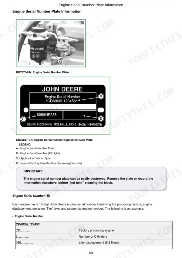
| General Information | 69-112 | Engine ID, Fuel/Oil/Coolant Specs, Storage |
| Fuel System - Repair and Components | 113-234 | Fuel Injection, ECU Mounting, Connector Repair |
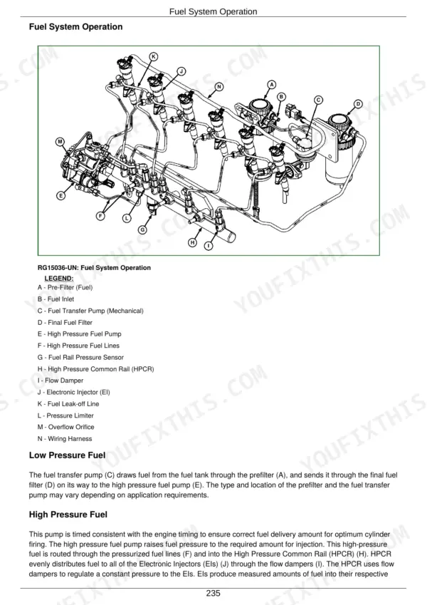
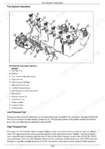
| Fuel System and Engine Control - Theory of Operation | 235-330 | HP Pump Operation, Turbocharger, CAN, Sensors |
| Diagnostics | 469-581 | DTC List, Service ADVISOR, ECU Replacement |
| Tools and Other Materials | Special Tools, Lubricants, Sealants | |
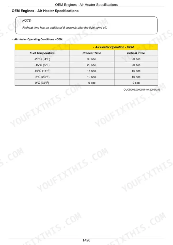
| Specifications | 1419-1426 | Torque Values, Application and Derate Specs |
| Wiring Diagrams | 1427-1507 | 4.5L / 6.8L 12V and 24V ECU Wiring Diagrams |
John Deere 4045, 6068 Common Problems This Manual Covers
Engine derates or throws codes after a sensor or wiring fault, and swapping parts blindly gets expensive fast.
The Diagnostics section pairs each DTC with a test procedure, so you verify the circuit with a meter against the ECU wiring diagrams before buying anything. It also covers ECU replacement correctly if the controller itself is at fault.
Manual Section: Diagnostics p. 316High pressure pump replaced but the engine runs rough or will not start because pump timing or torques were guessed.
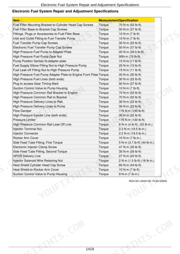
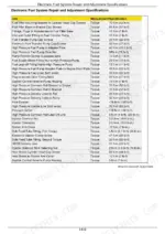
The Fuel System repair section gives the gear timing mark access procedure and the torques the factory actually prints: gear nut 95 N·m (70 lb-ft), pump to adapter plate 40 N·m (30 lb-ft), and a two-stage high pressure line torque of 5 N·m (4 lb-ft) to seat, then 22 N·m (16 lb-ft) plus a 60 degree turn at both ends. Follow that order and the pump goes back on without a weeping line.
Manual Section: Fuel System - Repair & Components p. 124Intermittent electrical faults from damaged ECU connectors, with codes that come and go on rough ground.
The connector repair procedures in the Fuel System section show pin extraction and terminal replacement for the ECU harness connectors, and the 12V/24V wiring diagrams let you trace each intermittent circuit back to the exact pin.
Manual Section: Wiring Diagrams p. 201Frequently Asked Questions
My engine suddenly lost power and is derating itself. Will this manual help me figure out why?
Yes, this is exactly what the Diagnostics section is built for. Sudden power loss on these engines is usually a plugged fuel filter, intake restriction, turbo fault or the ECU pulling power on purpose because of a sensor reading. The manual walks you through reading the DTCs, understanding how the ECU cuts fuel delivery once it detects a fault, and testing the actual components instead of guessing and throwing parts at it. p. 316
Does it cover the high pressure fuel pump - removal, timing and torque specs?
Yes, with the numbers the factory actually prints. The Fuel System repair section walks pump removal and installation including the drive gear timing procedure, and each fastener carries its own spec: pump to adapter plate 40 N·m (30 lb-ft), gear nut 95 N·m (70 lb-ft), pump position sensor 15 N·m (11 lb-ft), fuel supply elbow fitting nut 20 N·m (15 lb-ft). The high pressure lines are a two-stage job and that is where people get burned: 5 N·m (4 lb-ft) to seat them, then 22 N·m (16 lb-ft) plus a 60 degree turn at both ends. Torque them like ordinary fittings and you get a weeping rail connection. p. 125
Can I diagnose trouble codes without a dealer Service ADVISOR subscription?
The manual lists the DTCs and the diagnostic procedures behind them, so you can work most codes with a multimeter and the wiring diagrams included here. Some functions like ECU programming still need Service ADVISOR or a compatible tool, and the manual is honest about which steps those are. For sensor circuits, wiring faults and mechanical causes, this book plus basic tools gets you most of the way. p. 440
My 6068 is blowing black smoke and drinking fuel. Where do I start?
Start with the fuel system theory section so you understand what the ECU is trying to do, then follow the diagnostic procedures for fuel restriction and turbocharger problems. Black smoke on these engines is almost always air or fuel delivery: restricted filter, tired turbo, boost leak or the engine simply overloaded. The manual gives you the test sequence so you check the cheap stuff first. p. 359
Does it include wiring diagrams for both 12V and 24V systems?
Yes, the Wiring Diagrams section has ECU wiring for the 4.5L and 6.8L in both 12V and 24V configurations. That covers marine, generator and industrial applications that run 24V electrics. It also includes connector repair procedures, which is worth its weight because half the electrical gremlins on these engines are corroded or backed-out pins, not dead sensors. p. 1439
What happens when the ECU detects a sensor fault - does it just shut down?
The ECU will decrease fuel delivery, set a specific engine speed, or shut the engine down when sensor inputs exceed normal operating ranges, and a Diagnostic Trouble Code (DTC) will always accompany a derate. p. 316







