

Part of the John Deere Repair Manuals.
This 904-page John Deere Technical Manual (TM1638) covers the 444H, 544H, TC44H, and TC54H loaders and tool carriers down to the last bolt. Whether you're chasing this John Deere 544h technical manual pdf for a torque spec or a full transmission teardown, you get wiring diagrams for the electrical system, hydraulic schematics covering steering, brakes, and the loader circuit, and step-by-step procedures from axle removal to torque converter installation. Set the wheel cap screw torque to 675 N·m (500 lb-ft) and the wheel retainer cap screws to 620 N·m (460 lb-ft) before you roll it back into service. Guessing on transmission clutch clearances is how you end up pulling it apart twice. Bookmarked by system, so you jump straight from Park Brake to Electrical without scrolling through 900 pages.
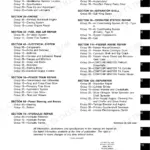
What's Inside This John Deere 444H, 544H, TC44H, TC54H Manual
| System | Pages | Key Topics |
|---|---|---|
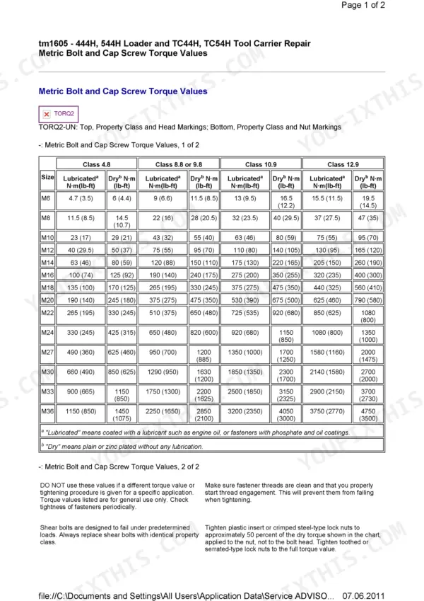
| General Information | 1-90 | Safety Information, Torque Values, Fuels and Lubricants |
| Wheels | 91-96 | Powered Wheels and Fasteners |
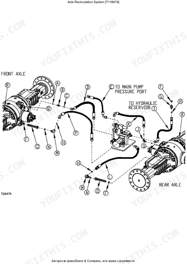
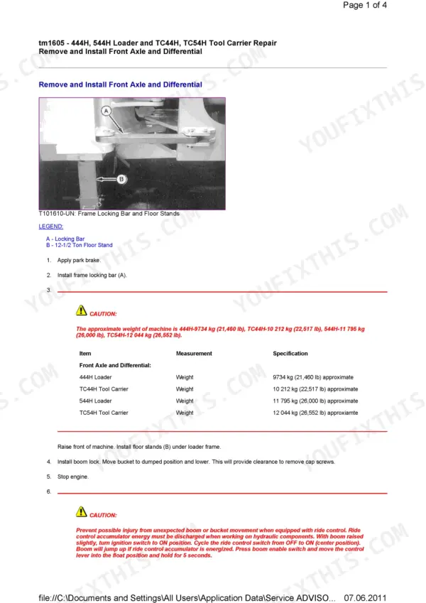
| Axles and Suspension Systems | 97-162 | Remove and Install Front Axle and Differential, Remove and Install Rear Axle and Differential, Remove and Install Universal Joint and Drive Shaft, Disassemble, Inspect |
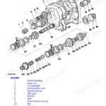
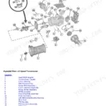
| Transmission | 163-305 | Remove and Install Transmission, Remove Torque Converter and Housing, Install Torque Converter and Housing, Remove Clutches, Input and Output Shafts, Install Clutches |
| Engine | 306-361 | Remove and Install Engine, Remove and Install Fluid Starting Aid Assembly, Remove and Install Fan and Fan Drive, Remove and Install Radiator and Oil Cooler |
| Engine Auxiliary Systems | 362-382 | Cold Weather Starting Aids, Cooling System, Speed Controls, Intake System, External Exhaust System, External Fuel Supply Systems |
| Dampener Drive | 383-385 | Elements |
| Steering System | 386-398 | Loader Start-Up Procedure (Steering Cylinder) |
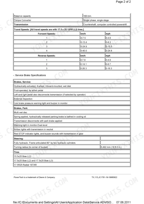
| Service Brakes | 399-411 | Remove and Install Brake Assembly, Remove and Install Brake Accumulator |
| Park Brake | 412-433 | Remove and Install Park Brake, Disassemble and Assemble Park Brake, Remove and Install Park Brake Release Solenoid Valve |
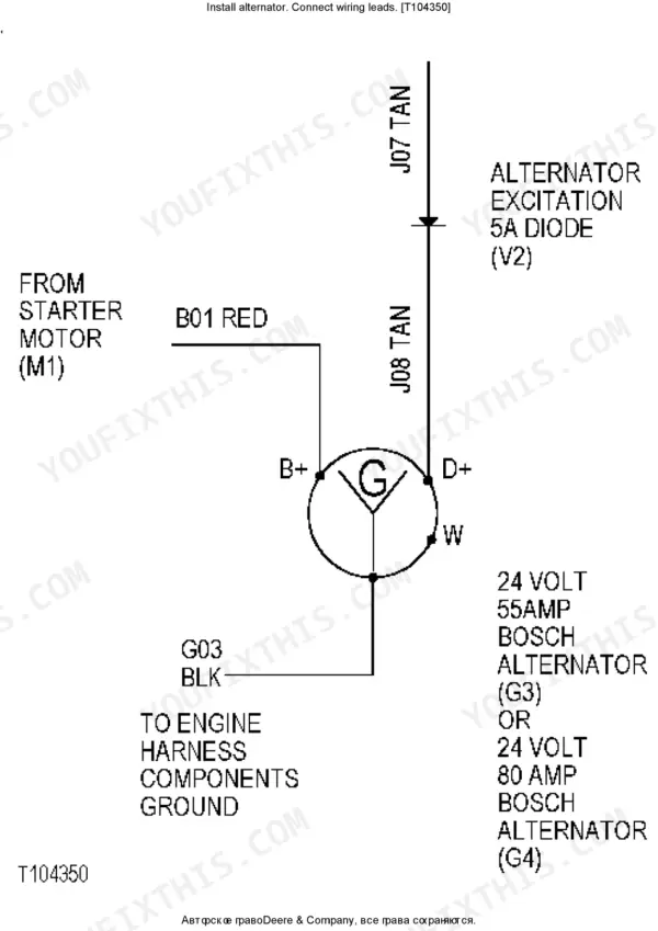
| Electrical System | 434-521 | Service Batteries Carefully, Battery Charging Procedure, Install Alternator Connect Wiring Leads, Remove and Install Work Lights, Replace Halogen Bulbs, Service Equipment and Tools |
| Frame or Supporting Structure | 522-575 | Welding Major Structure, Separate Engine and Loader Frame, Remove and Install Lower Pivot Bearing and Seals, Remove and Install Cab or Canopy |
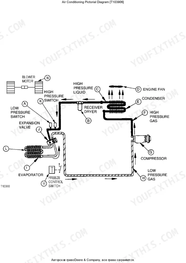
| Operator's Station | 576-655 | Essential Tools, Refrigerant Theory of Operation, R134a Refrigerant Recovery Recycling and Charging Station Installation Procedure, Charge R134a System |
| Sheet Metal and Styling | 656-672 | Hood or Engine Enclosure, Miscellaneous Shields, Grille and Grille Housing |
| Safety and Convenience | 673-684 | Mirror, Fire Extinguisher, Horn and Warning Devices |
| Loader | 685-904 | Remove and Install Bolt-On Cutting Edges and Wear Plates, Upper Tool Carrier Tilt Linkage-TC44H/TC54H, Specifications, Remove and Install Loader Hydraulic Pump |
Quick Reference Specifications
| Specification | Value | Page |
|---|---|---|
| Wheel Cap Screw Torque | 675 N·m (500 lb-ft) | p. 91 |
| Transmission Housing Cover Hex Nut | 9.5 N·m (85 lb-in.) | p. 181 |
| Hydraulic Oil Reservoir Capacity | 106 L (28 gal) approximate | p. 719 |
| Hydraulic Pump Weight | 38 kg (84 lb) approximate | p. 719 |
| Piston Shoe Wear (maximum dimension between shoe wear at outer dimension) | 0.025 mm (0.001 in) maximum | p. 719 |
| Boom Float Detent Pressure | 4137-4480 kPa (41-45 bar) (600-650 psi) in detent | p. 720 |
| Boom Power Down Pressure | 1860-2082 kPa (19-21 bar) (270-302 psi) | p. 720 |