
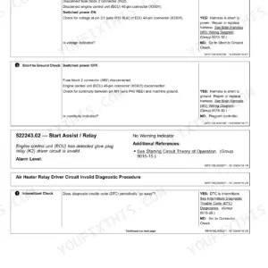
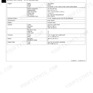
Part of the John Deere Repair Manuals.
Test and troubleshoot the John Deere 9410, 9510 and 9610 combines with TM1702, the Diagnosis and Tests manual from John Deere Harvester Works. It covers operational checkouts, electrical diagnostics with schematics, hydrostatic and hydraulic pressure tests, four-wheel drive, brakes, steering, DIAL-A-MATIC and R-134a air conditioning.
You trace electrical faults circuit by circuit with a multimeter, using the seven step electrical test procedure, connector end views and a circuit code listing. This is a test manual. Repair procedures are in the companion repair manual TM1701. Engine work is in CTM86 (6081) and CTM104 (6068).
What's Inside This John Deere 9410, 9510, 9610 Manual
| System | Pages | Key Topics |
|---|---|---|
| Contents and Companion Manuals | 1-10 | Cover, Companion Technical Manual List, Section and Group Contents |
| Safety and Combine Identification | 11-22 | Safety Messages, Combine and Component Serial Number Identification |
| General Specifications and Diagnostic Procedures | 23-42 | 9410, 9510 and 9610 Machine Specifications, Unified Inch and Metric Bolt Torque Values, Fitting Torque Charts, Diagnostic and Testing Procedures |
| Electrical System Operational Checkout | 43-78 | Road, Field and Warning Light Checks, Wiper, Fuel Pump, Gauges, HarvesTrak, Oil Pressure Warning, Grain Tank Full, Park Brake, Header Lift and Four-Wheel Drive Checks |
| Engine Operation | 79-90 | Cooling System and Rotary Screen, 6068 Engine (9410) and 6081 Bosch Engine (9510, 9610) Operation |
| Fuel and Air Intake | 91-102 | Air Intake System and Fuel System Operation and Tests |
| Electrical Diagnostic Information | 103-142 | Schematic Symbols, How to Use the Diagnostic Information, Service Tools, Seven Step Electrical Test Procedure, Visual Inspection, Wiring Diagram Information, Ground Points |
| Electrical Diagnostics: Seat Through Dial-A-Matic Type a | 143-344 | Air Suspension Seat, Alternator and Battery, Auxiliary Lights and Power Outlet, Backshaft Speed, Combine Data Center, Concave, Contour Master, Corn Head Deck Plates, Corner Post Gauges, Cylinder Speed, Dial-A-Matic Identification and Type a |
| Electrical Diagnostics: Dial-A-Matic Type B Through Injection Pump | 345-598 | Dial-A-Matic Type B, Dial-A-Speed, Digital Tachometer, Electric Fuel Pump, Engine Relay Panel, Oil Pressure Monitor, Fan Speed, Four-Wheel Drive, HarvesTrak, Header Engage and Raise/Lower, Heating and Air Conditioning, Horn, Injection Pump Systems for 6081 and 6068 |
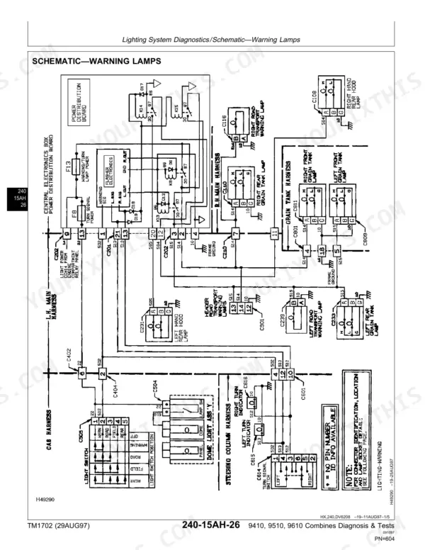
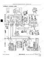
| Electrical Diagnostics: Lighting Through Power Distribution | 599-724 | Lighting System Schematics, Low Shaft Speed Monitor, Parking Brake, Power Distribution Board |
| Electrical Diagnostics: Radio Through Wiper | 725-888 | Radio, Reel/Belt Speed, Reel Fore/Aft and Raise/Lower, Separator Engage, Shoe Lighting, Starting Aid, Starting System, Unloading Auger Engage and Swing, Warning Display Panel, Wiper System |
| Circuit Code and Connector Listings | 889-974 | Circuit Code Listing, Connector Number Listing and End Views |
| Power Train | 975-1056 | Hydrostatic Drive Specifications, Transmission and Final Drives, Hydrostatic Adjustments and Operational Checks, Charge Pressure Low Diagnostics, Transmission Lubrication Pump, Hydrostatic Theory of Operation |
| Four-Wheel Drive | 1057-1094 | Four-Wheel Drive Operational Checkout, Diagnostics and Theory of Operation |
| Service and Park Brakes | 1095-1126 | Service Brake Diagnostics and Theory, Mechanical Park Brake Specifications, Diagnostics and Theory |
| Hydraulic System Diagnostics | 1127-1306 | Hydraulic Symbols, Diagnostic Specifications, Operational Tests and Adjustments, Backshaft Speed, Chaff Spreader, Corn Head Deck Plates, Cylinder Speed, Header Raise/Lower and Tilt, Overheating, Reel and Unloading Auger Swing Diagnostics with Circuit Diagrams |
| Hydraulic Theory of Operation | 1307-1418 | Theory of Operation for Backshaft Speed, Chaff Spreader, Deck Plates, Cylinder Speed, Header Raise/Lower and Tilt, Overheating, Overall Hydraulic System, Reel and Unloading Auger Swing |
| Main Engine Gearcase, Steering and Separator Drive | 1419-1508 | Engine Gearcase Hydraulic Specifications, Steering System Specifications, Diagnostics and Theory, Separator Drive Diagnostics, Unloading Auger Engage System |
| Dial-A-Matic System | 1509-1570 | Dial-A-Matic Adjustments, Identification, Type a and Type B Systems, Header Theory of Operation |
| Heating and Air Conditioning | 1571-1615 | Specifications and Special Tools, R-134a System Tests, Diagnostics and Theory of Operation |
| Index | 1616-1622 | Alphabetical Index |
Quick Reference Specifications
| Specification | Value | Page |
|---|---|---|
| Manual | TM1702 Diagnosis and Tests (29AUG97) | p. 1 |
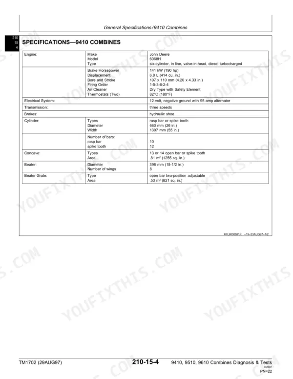
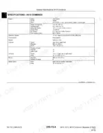
| Engine, 9410 | John Deere 6068H, 141 kW (190 hp), 6.8 L (414 cu. in.) | p. 26 |
| Engine, 9510 | John Deere 6081H, 8.1 L (499 cu. in.) | p. 28 |
| Engine, 9610 | John Deere 6081H, 8.1 L (499 cu. in.) | p. 30 |
| Electrical system | 12 volt, negative ground with 95 amp alternator | p. 26 |
| Grain tank capacity, 9410 | 6410 L (182 bu) | p. 27 |
| Grain tank capacity, 9510 | 7200 L (204 bu) | p. 29 |
| Grain tank capacity, 9610 | 8460 L (240 bu) | p. 31 |
| Hydraulic/hydrostatic reservoir capacity | 34 L (36 U.S. qts) | p. 27 |
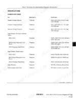
| Neutral charge pressure | 1586-2000 kPa (15.9-20.0 bar) (230-290 psi) | p. 979 |
| Forward/reverse charge pressure | 1413-1827 kPa (14.1-18.3 bar) (205-265 psi) | p. 979 |
| Reel/belt pickup relief pressure | 15 100 kPa (2190 psi) ± 250 psi | p. 1149 |
| Engine gearcase regulated pressure | 1207 kPa (12.1 bar) (175 psi) | p. 1423 |
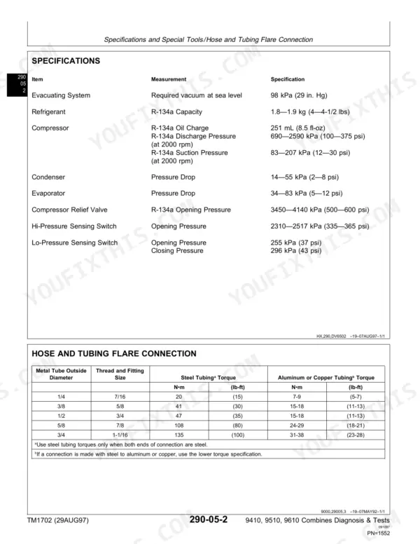
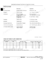
| Refrigerant | R-134a | p. 1574 |
| R-134a capacity | 1.8-1.9 kg (4-4-1/2 lbs) | p. 1574 |
| Compressor oil charge | 251 mL (8.5 fl-oz) | p. 1574 |
John Deere 9410, 9510, 9610 Common Problems This Manual Covers
Hydrostatic drive weak or charge pressure low
Check the hydraulic/hydrostatic reservoir level first. The reservoir is 34 L (36 U.S. qts). Then run the hydrostatic operational checks and adjustments in the Power Train section. If charge pressure reads low, follow the charge pressure low diagnostics and test the transmission lubrication pump.
Manual Section: Power Train: Hydrostatic Adjustments, Operational Checks and Charge Pressure Low Diagnostics p. 1009Reel speed not changing
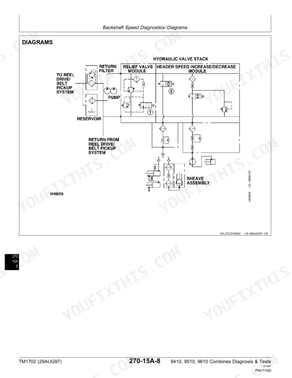
Find out whether the fault is electrical or hydraulic. Walk the Reel/Belt Speed electrical diagnostics with the schematics, then the hydraulic reel diagnostics and circuit diagrams. Reel/belt pickup relief pressure should be 15 100 kPa (2190 psi) plus or minus 250 psi. Use a pressure gauge rated for 34 475 kPa (5000 psi).
Manual Section: Electrical Diagnostics: Reel/Belt Speed; Hydraulic System Diagnostics: Reel p. 1149Unloading auger will not swing or engage
Swing and engage are separate systems, so test them separately. For swing, run the Unloading Auger Engage and Swing electrical diagnostics, then the hydraulic unloading auger swing diagnostics. For engage, the Main Engine Gearcase section covers the unloading auger engage system. It lists engine gearcase regulated pressure as 1207 kPa (12.1 bar) (175 psi).
Manual Section: Electrical Diagnostics: Unloading Auger Engage and Swing; Main Engine Gearcase: Unloading Auger Engage System p. 1497Warning lights or gauges not working
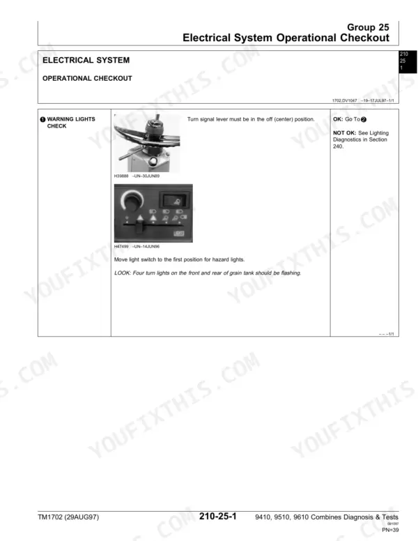
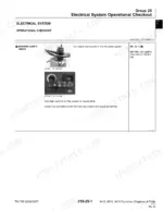
Start with the Electrical System Operational Checkout. It checks the warning lights and road lights, and the turn signal lever must be in the off (center) position. A failed step sends you to the warning display panel, corner post gauges or power distribution board diagnostics. Check the listed ground points along the way.
Manual Section: Electrical System Operational Checkout; Electrical Diagnostics: Warning Display Panel, Corner Post Gauges, Power Distribution Board p. 43Frequently Asked Questions
What is the charge pressure on a John Deere 9610 hydrostatic drive?
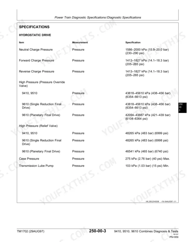
Neutral charge pressure is 1586-2000 kPa (15.9-20.0 bar) (230-290 psi). Forward and reverse charge pressure is 1413-1827 kPa (14.1-18.3 bar) (205-265 psi). Take the reading in neutral and in gear. The charge pressure low diagnostics in the Power Train section start from those two readings. p. 979
Which engine is in a John Deere 9510 combine?
The 9510 uses the John Deere 6081H, 8.1 L (499 cu. in.), with Bosch fuel injection. The 9610 also uses the 6081, and the 9410 runs the 6068. This book covers engine operation, the cooling system and rotary screen, fuel and air intake tests, and the injection pump circuits. Engine service information is in CTM86 (6081) and CTM104 (6068). p. 85
How do I test the DIAL-A-MATIC header height control on a 9610?
First work out whether the combine has type A or type B, because the book splits the diagnostics that way. The electrical groups for each type include schematics and use the seven step electrical test procedure. The hydraulic side is tested under header raise/lower and tilt. The DIAL-A-MATIC section adds the adjustments and header theory of operation. p. 1515
How much refrigerant does a 9410 combine air conditioner take?
The system takes R-134a refrigerant, capacity 1.8-1.9 kg (4-4-1/2 lbs), with a compressor oil charge of 251 mL (8.5 fl-oz). The Heating and Air Conditioning section also lists the special tools, R-134a system tests and diagnostics. That lets you confirm a charge problem before you open the system. p. 1574
Does this manual list fault codes for the electrical system?
Yes, for the engine. The 6081 Type B engine control section lists numbered ECU diagnostic error codes shown on the dual display digital tachometer, starting with 21 Sensor Supply Voltage - High (p. 564). For the rest of the electrical system you trace faults with a multimeter, the seven step electrical test procedure, schematics, connector end views and ground point locations. The system is 12 volt, negative ground with 95 amp alternator. Circuits from the air suspension seat to the wiper system each have their own diagnostic group. p. 129








Reviews
There are no reviews yet.