
Part of the John Deere Repair Manuals.
Engine removal, cooling, fuel and air, electrical, power train and the hydrostatic drive are each covered step by step for the 9410, 9510 and 9610 straw walker combines. Each one goes through remove, disassemble, inspect, assemble and adjust. Steering and brakes, hydraulics, R134a air conditioning, feeder house, separator, grain tank and unloading, and the engine gearcase follow the same pattern.
This is the repair book, TM1701. Diagnosis and tests are in TM1702. Engine service information is in CTM86 for the 6081 and CTM104 for the 6068. Torque values are printed at the steps that need them.
What's Inside This John Deere 9410, 9510, 9610 Repair Manual
| System | Pages | Key Topics |
|---|---|---|
| Contents and Companion Manuals | 1-6 | Cover, Companion Technical Manual List, Section Contents |
| General: Safety, Tune-Up, Fuels and Lubricants | 7-18 | Safety, Tune-Up and Adjustment, Fuels and Lubricants |
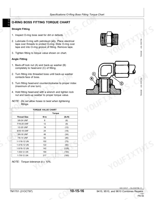
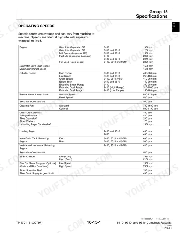
| Identification and Specifications | 19-60 | Combine and Component Serial Number Locations, 9410, 9510 and 9610 Machine Specifications, Operating and Ground Speeds, Bolt and Fitting Torque Charts |
| Engine | 61-106 | Remove and Install Engine (6068 on 9410, 6081 on 9510 and 9610), Cooling System, Lower Engine Repair |
| Fuel and Air Repair | 107-126 | Air Intake System, Diesel Fuel System |
| Electrical System | 127-216 | Components, Bulbs and Switches, Batteries, Harness and Connector Repair, Gauges and Monitors, Wiper and Radio, Alternator, Starting Motor, Electrical Engine Control |
| Power Train Repair | 217-400 | Transmission and Differential, Ring and Pinion Final Drive, Planetary Final Drive, Hydrostatic System, Cam Lobe Motor, Tires and Wheels |
| Power Steering and Brakes | 401-446 | Steering, Brakes, Steering Pump, Steering Valve, Steering Cylinder, Toe-In Adjustment, Brake Shoe, Master Cylinder |
| Hydraulic Repair | 447-542 | Hydraulic Reservoir, Pumps, Valves, Cylinders, Motors, Accumulator, Reel/Belt Pickup Pump Drive |
| Separator Shell | 543-548 | Gull Wing Doors, Cleaning Fan Shields |
| Operator Station Repair | 549-684 | Air Conditioning System (R134a), System Components |
| Feeder House Repair | 685-808 | Feeder House Conveyor, Conveyor Drum, Conveyor Shaft and Slip Clutch, Feeder House Drives and Reverser, Contour Master Platform Driveshafts, Tilt Cylinder and Tilt Frame |
| Separator | 809-1068 | Separator Repair, Cylinder Drives, Straw Walkers and Crankshafts, Straw Chopper and Spreader, Shoe Supply Augers and Cleaning Fan, Tailings Elevator, Primary Countershaft Gearcase, Header Electromagnetic Clutch |
| Grain Tank and Unloading System Repair | 1069-1190 | Grain Tank Cross Augers, Unloading Auger Drives, Vertical and Horizontal Unloading Augers, Clean Grain Elevators, Grain Tank Extensions |
| Engine Gearcase and Control Valve Repair | 1191-1238 | Engine Gearcase and Valve, Separator Drive Wet Clutch, Hydrostatic Gear Set, Hydrostatic Pump Drive, Oil Screen |
| Index | 1239-1246 |
Quick Reference Specifications
| Specification | Value | Page |
|---|---|---|
| Manual | TM1701 Repairs (31OCT97) | p. 1 |
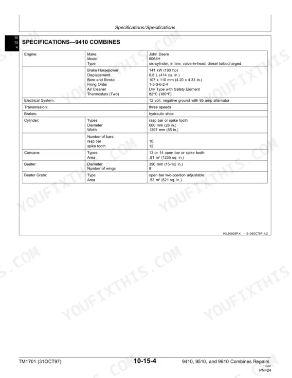
| Engine, 9410 | John Deere 6068H, 141 kW (190 hp), 6.8 L (414 cu. in.) | p. 26 |
| Engine, 9510 | John Deere 6081H, 8.1 L (499 cu. in.) | p. 28 |
| Engine, 9610 | John Deere 6081H, 8.1 L (499 cu. in.) | p. 30 |
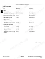
| Electrical system | 12 volt, negative ground with 95 amp alternator | p. 26 |
| Grain tank capacity, 9410 | 6410 L (182 bu) | p. 27 |
| Grain tank capacity, 9510 | 7200 L (204 bu) | p. 29 |
| Transmission capacity | 9.6 L (10 U.S. qts) | p. 27 |
| Hydraulic reservoir capacity | 34 L (36 qt) | p. 447 |
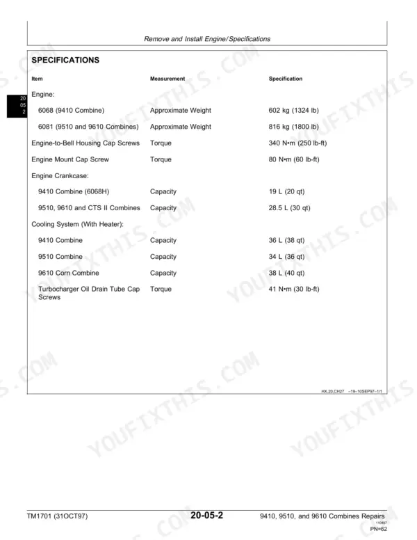
| Engine-to-bell housing cap screws | 340 N·m (250 lb-ft) | p. 64 |
| Engine mount cap screws | 80 N·m (60 lb-ft) | p. 64 |
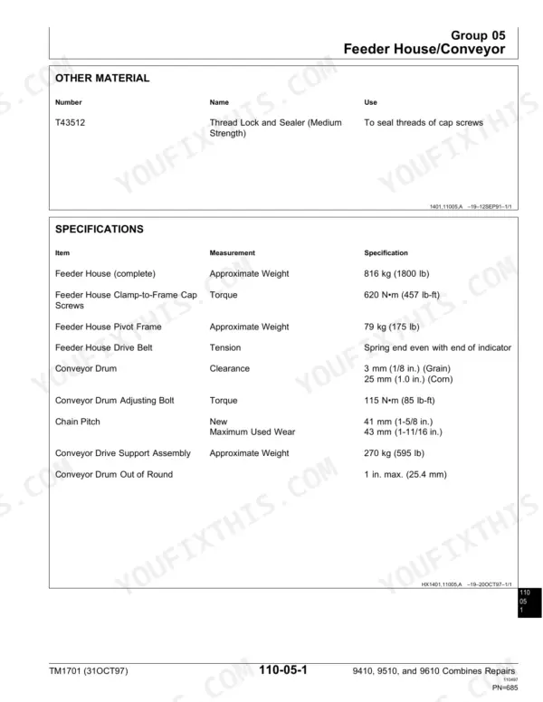
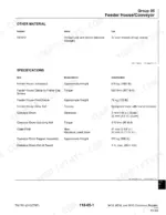
| Feeder house clamp-to-frame cap screws | 620 N·m (457 lb-ft) | p. 687 |
| Refrigerant | R134a | p. 549 |
John Deere 9410, 9510, 9610 Common Problems This Manual Covers
Hydrostatic drive leaking or weak
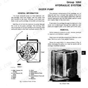
Power train repair covers the hydrostatic system and the cam lobe motor with removal, disassembly, inspection and assembly steps. Replace seals and worn parts using that procedure. If the drive is weak but not leaking, check pressures first with the companion Diagnosis and Tests volume, which this book names for complete service information.
Manual Section: Power train repair: hydrostatic system, cam lobe motor p. 289Unloading auger drive worn
Grain tank and unloading system repair takes apart the unloading auger drives, then the vertical and horizontal unloading augers and the grain tank cross augers. Inspect gears, bearings and flighting as each piece comes out, then assemble and adjust following the section.
Manual Section: Grain tank and unloading system repair: unloading auger drives p. 1077Straw walker crankshaft bearings worn
The Separator section has its own procedure for straw walkers and crankshafts. It takes you through pulling the walkers, removing the crankshafts, and inspecting the bearings before assembly. If the drive side is worn too, the cylinder drives and primary countershaft gearcase are in the same section.
Manual Section: Separator: straw walkers and crankshafts p. 919Brakes worn
Power steering and brakes covers brake removal, disassembly, inspection and assembly, with steering repair right beside it. Work through the brake components, replace the worn parts, then adjust them the way the section directs before the combine moves under its own power again.
Manual Section: Power steering and brakes: brakes p. 425Frequently Asked Questions
How do I remove the engine from a John Deere 9610 combine?
The Engine section covers remove and install for the 6081 used in the 9510 and 9610. Lift it with the JDG-23 lifting sling. Engine-to-bell housing cap screws go back at 340 N·m (250 lb-ft), and engine mount cap screws at 80 N·m (60 lb-ft). Internal engine repair is in CTM86, not this book. p. 63
Which engine is in a John Deere 9510 combine?
The 9510 runs a John Deere 6081H, 8.1 L (499 cu. in.), the same engine family as the 9610. The 9410 gets the 6068H, 141 kW (190 hp), 6.8 L (414 cu. in.). This manual handles removal, cooling and lower engine repair. The matching CTM covers the rest. p. 28
How do I replace the feeder house chain on a 9610?
Feeder house repair covers the conveyor, the conveyor drum, and the conveyor shaft and slip clutch, so the chain and drum come out in order. Feeder house clamp-to-frame cap screws take 620 N·m (457 lb-ft). The drives, reverser, tilt cylinder and tilt frame are in the same section. p. 694
What refrigerant does a 9410 combine air conditioner use?
R134a. The air conditioning system is under Operator station repair, with removal and installation of the cab system components. Pressure checks and diagnosis of a system that will not cool are in the separate TM1702 manual. p. 549
Does this manual include wiring diagrams or diagnostic tests?
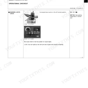
No. This is the repair volume: remove, install, disassemble, inspect, assemble and adjust. Schematics, operational checkouts and test procedures are in TM1702 Diagnosis and Tests. The Electrical section here covers harness and connector repair, gauges, the alternator and the starting motor. p. 127









Reviews
There are no reviews yet.