Part of the John Deere Repair Manuals.
Need real factory data for your John Deere 1010 U, 1010 R, or 1010 O? This 568-page John Deere 1000 and 1010 service manual PDF (OEM SM2033) covers every variant, Row-Crop Utility, Special Row-Crop Utility, Single Row-Crop, Grove and Orchard, gasoline and diesel alike. Inside you get wiring diagrams for the full electrical system, hydraulic schematics for both single and dual systems, engine teardown and rebuild procedures for gas and diesel blocks, plus transmission, differential, final drive, power steering, and 3-point hitch service. Torque tables and a troubleshooting section back up every job. Test the hydraulic pump, set the relief valve to the printed factory pressure, then check valve clearance during tune-up before you button it up. Your tractor is sixty years old; forum guesses won't cut it. Bookmarked and keyword-searchable: type the spec, find the page, start wrenching.
What's Inside This John Deere 1010 RU, RUS, RS, U, R, O Manual
| System | Pages | Key Topics |
|---|---|---|
| Description | 5-22 | Tractor Models, Common Features, Engine Specifications, Axle Types, Hydraulic System |
| Periodic Lubrication | 23-36 | Lubrication Timetable, Engine Oil Viscosity, Grease Types, Service Intervals, Detailed Service Procedures |
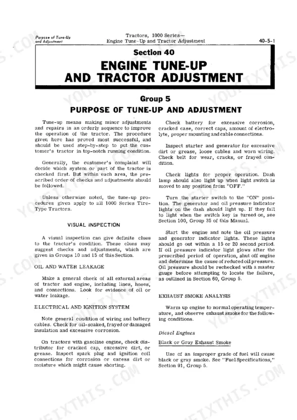
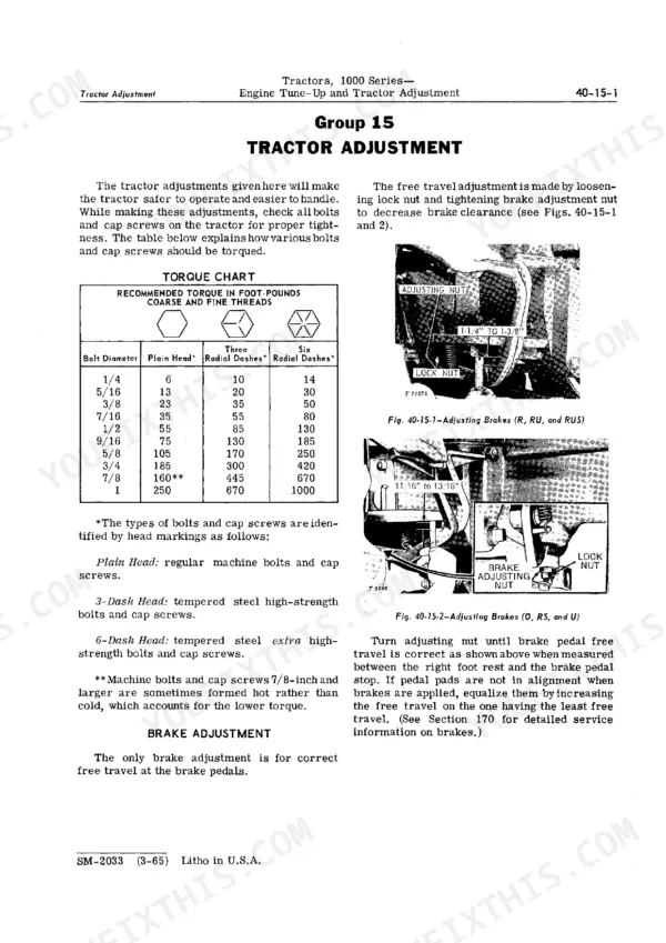
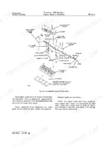
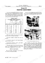
| Engine Tune-Up and Tractor Adjustment | 37-54 | Visual Inspection, Compression Test, Ignition Timing, Valve Clearance, Fuel System Adjustments |
| Engine (Basic) - Gasoline | 55-88 | Four-Cylinder 115 Cu in Gasoline Engine (7.9:1 Compression, 85 Ft-Lb Max Torque), Carburetor and Ignition Components, Sleeve-and-Deck Cylinder Assembly, Cylinder Head Service, Piston and Rod Service, Crankshaft and Bearings |
| Engine (Basic) - Diesel | 89-122 | Four-Cylinder 145 Cu in Diesel Engine (19:1 Compression, 85 Ft-Lb Max Torque), Injection Pump and Fuel Filters, Sleeve-and-Deck Cylinder Assembly, Cylinder Head Service, Piston and Rod Service, Crankshaft and Bearings |
| Engine Lubrication System | 123-132 | Oil Pump Description, Oil Pump Removal, Oil Pump Inspection, Oil Filter Service, Lubrication System Specifications |
| Governor and Speed Control Linkage | 133-168 | Governor Operation, Governor Removal, Speed Control Linkage Adjustment, Throttle Stop Adjustment, Fast/Slow Idle Adjustment |
| Gasoline Fuel System | 169-242 | Carburetor Description, Carburetor Disassembly, Fuel Tank Removal, Fuel Filter Servicing, Air Cleaner Service |
| Transmission and Differential | 243-346 | Transmission Operation, Shifter Mechanism, Differential Removal, Output Shaft Adjustment, Transmission Specifications |
| Belt Pulley | 347-358 | Belt Pulley Description, Disassembly and Repair, Bearing Adjustment, Pinion Shaft Preload, Belt Pulley Specifications |
| Final Drives | 359-368 | Final Drive Description, Removal and Disassembly, Axle Shaft Bearings, Pinion Gear Inspection, Final Drive Specifications |
| Brakes | 369-376 | Brake System Description, Brake Removal, Actuating Disk Assembly, Brake Pedal Adjustment, Brake Specifications |
| Steering Mechanism | 377-392 | Steering Wheel and Shaft, Steering Gear Disassembly, Front End Support Removal, Axle Pivot Shaft, Toe-In Adjustment |
| Power Steering | 393-412 | Power Steering Description, Steering Valve Operation, Steering Cylinder Service, Relief Valve Adjustment, Oil Line Servicing |
| Front Axles | 413-428 | Adjustable Front Axles, Tricycle Front Axles, Roll-O-Matic Wheels, Spindle and Knuckle, Toe-In Adjustment |
| Hydraulic System | 429-558 | Single Hydraulic System, Dual Hydraulic System, Remote Hydraulic Control, Hydraulic Pump Testing, Relief Valve Adjustment |
| Seats | 559-568 | Regular Seat Adjustment, Deluxe Seat Description, Seat Removal, Spring Arm Disassembly, Adjuster Handle Service |
Quick Reference Specifications
| Specification | Value | Page |
|---|---|---|
| All Models | ||
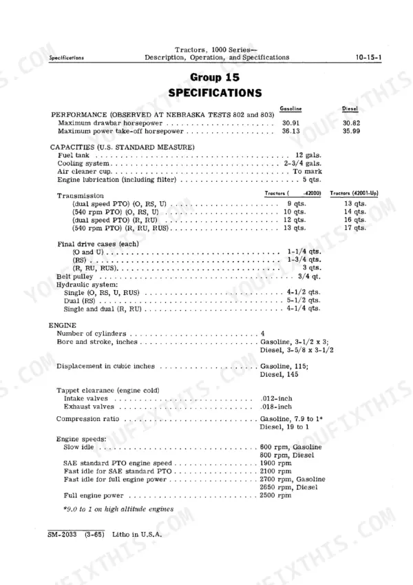
| Engine bore | 3-1/2 in. | p. 6 |
| Engine stroke | 3 in. | p. 6 |
| Cylinder head bolt torque | 150 ft-lb | p. 44 |
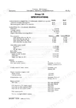
| Hydraulic relief valve pressure setting | 1,040 to 1,080 psi | p. 434 |
| Lubrication interval | Every 100 hours | p. 29 |
| Coolant level check interval | At least every 200 hours | p. 29 |
| gasoline | ||
| Gasoline engine displacement | 115 cu in., 4-cylinder, 7.9:1 compression | p. 55 |
| diesel | ||
| Diesel engine displacement | 145 cu in., 4-cylinder, 19:1 compression | p. 89 |
John Deere 1010 RU, RUS, RS, U, R, O Common Problems This Manual Covers
John Deere 1010 engine cranks slowly or won't start, battery drains down after sitting overnight
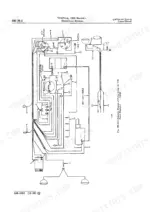
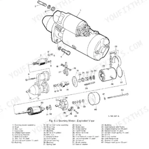
Test each cell with a hydrometer; anything below 1.225 specific gravity means half charge or worse, so recharge at 15 amperes for 30 minutes. These tractors ground the positive post, noted on page 238, so hook the charger accordingly. Clean both terminals and the ground strap before condemning the starter.
Manual Section: Gasoline Fuel System p. 212Hydraulic lift raises slowly or not at all, pump makes a whining noise under load
Connect a pressure gauge and check the relief valve against the 1,040 to 1,080 psi setting on page 434. If pressure reads low, turn the adjusting screw in to raise it or out to lower it, per page 451. A whining pump usually means cavitation, so verify reservoir level and prime the pump after any replacement.
Manual Section: Hydraulic System p. 434Clutch chatters and throw-out bearing squeals or growls every time the pedal is depressed
Grease the throw-out bearing carrier fitting every 100 hours of operation with SAE multipurpose grease; page 240 covers the fitting. A dry bearing squeals first, then seizes, and replacing it means splitting the tractor. If the noise continues after greasing, pull the clutch housing and inspect the bearing and carrier for wear.
Manual Section: Periodic Lubrication p. 29Engine overheats and pushes coolant during heavy fieldwork, temperature gauge climbs into the red
Drain and refill the cooling system to its full 2-3/4 gallon capacity listed on page 19, then blow out the radiator core and cooling fins with compressed air. Service the air cleaner, since a plugged element makes the engine run rich and hot. Check fan belt tension and the thermostat before blaming the head gasket.
Manual Section: Engine Tune-Up and Tractor Adjustment p. 37Transmission jumps out of gear or grinds when shifting, no power reaching rear wheels
Check the shifter linkage for misalignment and worn detents before pulling the transmission apart. Drain the fluid and look for metal; contaminated oil chews up synchronizer surfaces fast. If the case has been off, torque the transmission to center-frame cap screws to 170-180 foot-pounds as listed on page 320, then recheck gear engagement.
Manual Section: Transmission and Differential p. 243Frequently Asked Questions
How to adjust the hydraulic lift arm maximum raise on John Deere 1010?
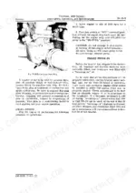
To adjust the lift arm maximum raise, pull the control lever to the extreme rear position, hydraulically raising the lift arms as far as they will go. Then push the arm up by hand until it comes to rest against the stop in the rockshaft housing. The angle of the inner lift arm when fully raised should be 56 degrees for Row-Crop and Row-Crop Utility Tractors, and 50 degrees for Single Row-Crop Tractors. p. 497
What are the torque specifications for the cylinder head bolts on a John Deere 1010 tractor?
The cylinder head bolts on a John Deere 1010 tractor should be torqued to 150 foot-pounds. This specification is consistent for both gasoline and diesel models. p. 87
How do you adjust valve lash on a John Deere 1010 engine?
To adjust valve clearance, ensure the engine is cold and the No. 1 cylinder piston is at top dead center on its compression stroke. Set intake valves to .012-inch and exhaust valves to .018-inch. Then, turn the crankshaft 1/2 revolution (180°) to set valves for cylinders No. 3, No. 4, and No. 2 in sequence. p. 44
How can internal hydraulic lift leaks be diagnosed on a John Deere 1010?
To diagnose internal leaks, install a heavy implement on the lift arms and leave it in a raised position for 15 to 20 minutes with the engine shut off. If the lift arms move down, possible causes include leaking check valve, piston sealing rings, pipe plugs in oil passages, or cylinder head seals. p. 435
What are the replacement conditions for the clutch throw-out bearing on a John Deere 1010?
The clutch throw-out bearing should be replaced if there is evidence of overheating, such as blue discoloration of the surface, or if the bearing feels rough. No specific dimensions are provided for replacement, only conditions for serviceability. p. 239
What do I get after purchasing this John Deere 1010 RU & variants manual?
You get a 568-page searchable PDF that downloads instantly after checkout. Open it on your laptop, tablet, or phone, and bring it right to the shop floor.
Can I print pages of this manual for my own shop?
Yes. Print the pages or sections you need for your own shop use. Any standard printer works.