


Part of the John Deere Repair Manuals.
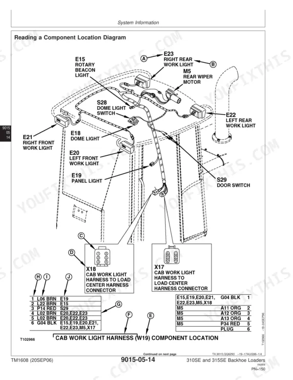
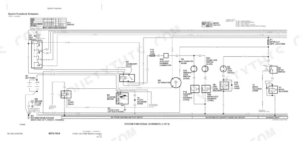
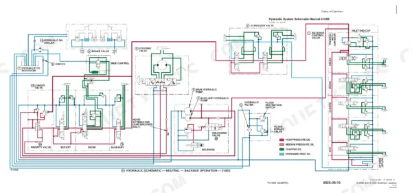
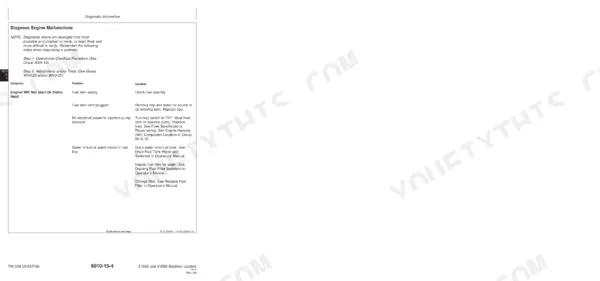
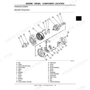
Need the factory specs for your backhoe loader? This 624-page John Deere 310se, 315se technical manual pdf (OEM #TM1608) breaks down the complete engine, power train, and hydraulic systems. Inside, you get detailed electrical wiring diagrams, full-system hydraulic schematics, and extensive troubleshooting charts to track down stubborn faults. Open up to page after page of calibration procedures, exploded views, and torque tables to rebuild your equipment right. Keep in mind that the torque tolerance for flat face O-ring seal fittings is +15 to 20 percent, and confirm your rear tires (without MFWD) are running the correct 19.5L-24 setup before rolling out of the shop. Your machine is sitting dead in the dirt, costing you money. Grab this text-searchable, bookmarked file, pull it up on your laptop or tablet, and fix it today.
What's Inside This John Deere 310SE, 315SE Manual
| System | Pages | Key Topics |
|---|---|---|
| General Information | 7-62 | Safety Information (Handle Fluids Safely, Avoid Fires, Prevent Battery Explosions, Prepare for Emergencies, Prevent Acid Burns, Handle Chemical Products Safely) |
| Operational Checkout Procedure | 63-90 | Fnr, Neutral Start Circuit, Reverse Warning Alarm, Park Brake, Charge Indicator Light, Tachometer/Hour Meter Circuit, Engine Speed Control Linkage, Brake System |
| Engine | 91-134 | PowerTech 4.5 L (4045) John Deere Engine, JT05801 Clamp-On Electronic Tachometer, Cylinder Block, Crankshaft, Piston, Fuel Injection Pump, Turbocharger, Radiator |
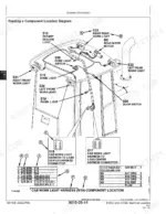
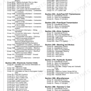
| Electrical System | 135-296 | Lock Harness, Air Conditioning Compressor Harness, Radio Harness, Selective Flow Valve Harness, Ride Control Harness, Pin Disconnect Harness, Cab Roof Harness, Cab Side Console Harness |
| Power Train | 297-434 | Clutch Pack, Torque Converter, Synchronizer, Transmission Pump, Transmission Filter, Manual Shift Transmission, MFWD, Transmission Control Valve |
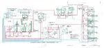
| Hydraulic System | 435-568 | Open-Center Hydraulic System, Hydraulic System Component, Hydraulic Pumps, Unloading Valve, Hydraulic Filter, Steering Valve, Priority Valve, Ride Control Hydraulic Component |
| Heating and Air Conditioning | 569-624 | Refrigerant, Air Conditioning Circuit, Blower Circuit, Receiver/Dryer, Expansion Valve, Compressor Relief Valve, Temperature Control, Compressor |
Documents This Manual Refers To
The manufacturer cites these publications by number. We carry them:
Quick Reference Specifications
| Specification | Value | Page |
|---|---|---|
| Alternators and Starting Motors | CTM77 | p. 1 |
| Tire pressure | Always maintain the correct tire pressure. Do not inflate the tires above the recommended pressure. | p. 16 |
| Tires | Front w/o MFWD—11L-15, 8 PR F3; Front w/o MFWD—11L-16, 12PR F3; Front with MFWD—12.5/80, 10PR; Rear w/o MFWD—16.9-24, 8PR R4; Rear w/o MFWD—19.5L-24, 8PR R4; Rear with MFWD—19.5L-24, 8PR R4 | p. 32 |
| Air cleaner | Dual stage dry, with element and precleaner | p. 32 |
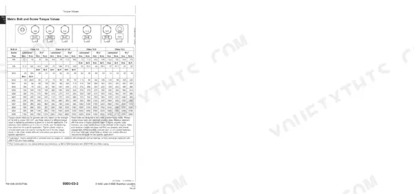
| Torque tolerance for Flat Face O-Ring Seal Fittings | +15-20% | p. 46 |
| Air filter replacement | when indicator shows red or when there is excessive smoke or loss of power | p. 99 |
| Battery-Minimum Open Circuit Voltage | 12.50 volts | p. 288 |
| 100% Charged Stabilized Open Circuit-Voltage | 12.5 volts or more | p. 288 |
| System relief valve (J) for both loader and backhoe or stabilizer functions | pilot operated and screw adjustable with anti-cavitation | p. 459 |
| System Relief Valve (S.N. —943225) | S.N. —943225 | p. 470 |
| Priority valve problem | Test operation of priority valve. Do Steering Priority System Relief Test in Group 9025-25. | p. 510 |
John Deere 310SE, 315SE Common Problems This Manual Covers
John Deere 310SE, 315SE hydraulics slow or dead on the backhoe, bucket barely lifts under load
Check the dual stage system relief valve on page 468; it's a common failure point causing pressure loss. Connect a gauge to the backhoe circuit and confirm relief pressure reaches 25 000 kPa (3625 psi) per page 30. If it falls short, remove the valve, inspect the seat, and replace it.
Manual Section: Hydraulic System Problems p. 468Slow hydraulics on the loader combined with sluggish or unresponsive steering at idle
Test the priority valve using the Steering Priority System Relief Test on page 510. Connect a gauge to the load sense circuit and confirm relief pressure holds at 19650 kPa (2850 psi) per page 538. If pressure won't hold, the spool is likely sticking or worn; remove, clean, and inspect before replacing.
Manual Section: Hydraulic System Problems p. 510No-start or hard start condition with dim lights and slow cranking in the morning
Check battery open circuit voltage with a multimeter; a fully charged battery should read 12.50 volts or more per page 288. Verify the battery meets the 750 amp cold cranking rating on page 289 before condemning the starter. Clean and tighten both terminals, then retest for slow cranking.
Manual Section: Electrical System Diagnostics - Power Circuit p. 288Hydraulic oil overheats and turns foamy after extended digging cycles during hot weather operation
Check the hydraulic oil cooler for a clogged core; pressure differential should not exceed 379 kPa (55 psi) per page 544. Drain the reservoir, which holds 37 L (39 qt) per page 34, and check for water contamination. Replace the filter if the by-pass valve chatters, per page 518, then refill with clean fluid.
Manual Section: Hydraulic System Problems p. 544Excessive tire wear or uneven tread pattern developing much sooner than expected
Check tire pressure at every shift; never inflate above the recommended pressure noted on page 16, since overinflation accelerates wear. Confirm tire size matches spec on page 32; rear tires without MFWD should be 19.5L-24, 8PR R4. Rotate tires on a set interval and inspect sidewalls for cuts or bulges.
Manual Section: General Information p. 32Frequently Asked Questions
What are the replacement specifications for the System relief valve (old style replacement) on John Deere 310SE and 315SE backhoe loaders?
For the 310SE and 315SE (S.N. -870248) models, the Loader System Relief Valve Setting Pressure is 20 684 kPa (207 bar) (2900 psi) and the Backhoe System Relief Valve Setting Pressure is 24 821 kPa (248 bar) (3525 psi). The High Pressure Lock Nut Torque and Low Pressure Lock Nut Torque are both 45 N•m (33 ft-lb.). p. 529
What is the engine oil capacity for the John Deere 310SE and 315SE backhoe loaders?
The engine oil capacity, including the filter, for the John Deere 310SE and 315SE backhoe loaders is 8.5 L (9.0 qt). p. 34
What is the specified torque for ROPS mounting bolts on the John Deere 310SE and 315SE?
The ROPS mounting bolts should be tightened to a torque of 420 ± 84 N•m (310 ± 62 lb-ft). p. 39
What are the slow and fast idle engine speeds for the John Deere 310SE and 315SE?
The specified slow idle speed is 900 + 25 - 0 rpm, and the fast idle speed is 2375 + 25 - 0 rpm. p. 120
How will I receive this John Deere 310SE Technical Manual?
Instant PDF download. You get the full 624-page searchable Technical Manual immediately after payment. Open it on your laptop, tablet, or phone right in the shop.
Am I able to print pages from this John Deere 310SE manual?
Yes. Print a chapter or just the pages for the job at hand, for use in your own shop. Any home or office printer works.
Does this John Deere 310SE Technical Manual have electrical diagrams?
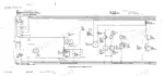
A wiring diagram for the John Deere 310SE, 315SE electrical system is included.








