


Part of the John Deere Repair Manuals.
All 446 pages of this John Deere X495, X595 Technical Manual (OEM #TM2024) target one machine family: the X495 and X595 Lawn and Garden Tractors, diesel-powered and built for real work. Inside, you get complete wiring schematics with circuit-level detail across the full electrical system, hydraulic schematics tracing every fluid path through the hydrostatic drive, and a thorough troubleshooting section covering engine, electrical, power train, steering, brakes, and attachment systems. Exploded views run deep through the manual, backed by fastener torque tables and step-by-step repair procedures for everything from mower deck spindles to the hydrostatic transmission. Torque the cylinder head bolts to 59-64 N•m (44-47 lb-ft) with lubricating oil applied, then fill the engine with 2.8 L after every filter swap. Your X595 diesel is down and you need real numbers, not forum guesses. Bookmarked and searchable: jump to any section, find the spec, fix the machine.
What's Inside This John Deere X495, X595, X595 4WD DIESEL Manual
| System | Pages | Key Topics |
|---|---|---|
| Introduction | 3-4 | Manual Description, Table of Contents, Specifications and Information, Identification Numbers, Tools and Materials, Component Location |
| Safety | 5-10 | Recognize Safety Information, Understand Signal Words, Handle Fluids Safely - Avoid Fires, Prevent Battery Explosions, Use Care in Handling and Servicing Batteries |
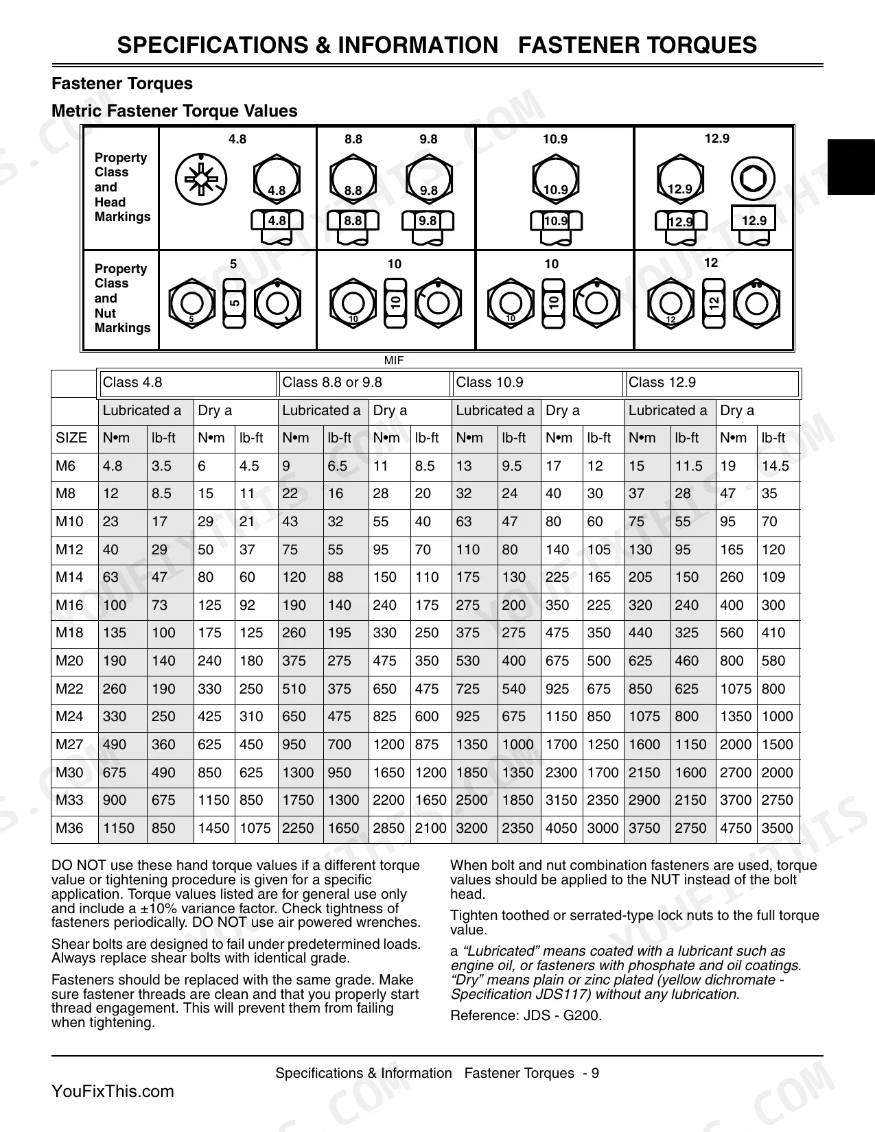
| Specifications & Information | 11-24 | Fastener Torques, O-Ring Seal Service Recommendations, General Information, Diesel Fuel, 4 - Cycle Diesel Engine Oil, Coolant Specifications |
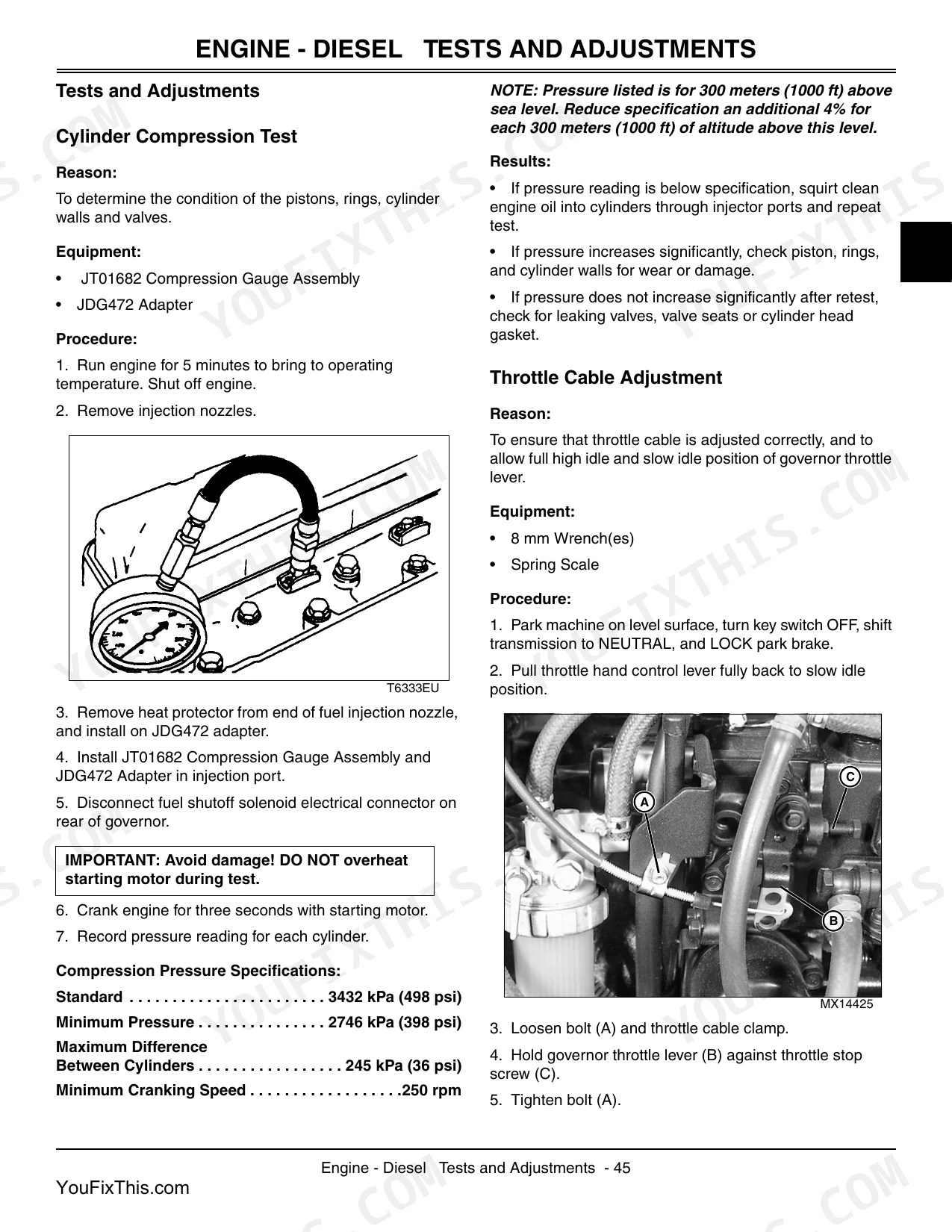
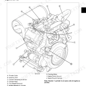
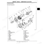
| Engine - Diesel | 25-110 | Specifications, Theory of Operation, Component Location, Diagnostics, Tests and Adjustments, Repair |
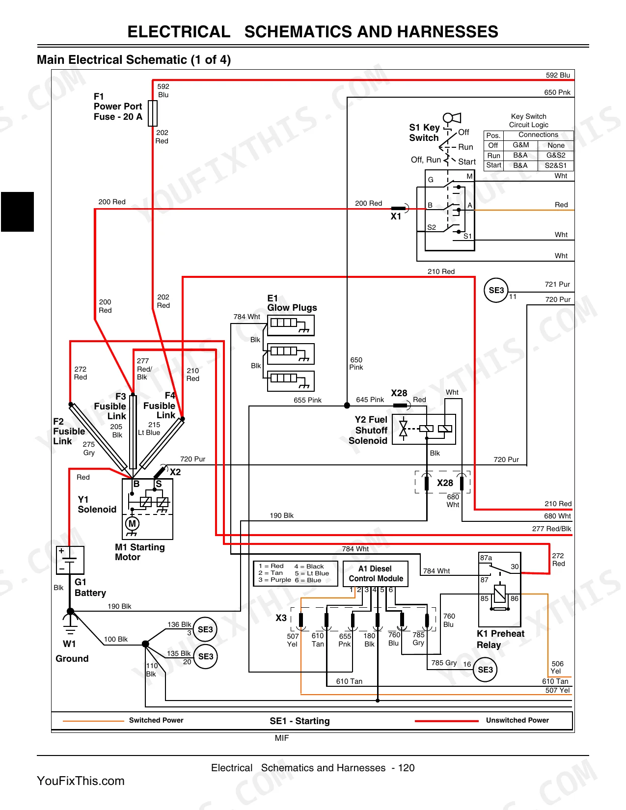
| Electrical | 111-206 | General Information, Specifications, Component Location, Schematics and Harnesses, Operation and Diagnostics, Tests and Adjustments |
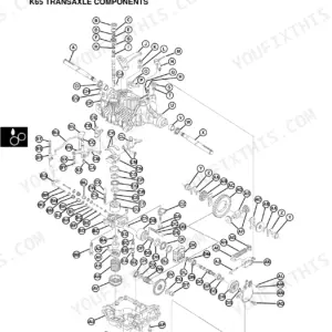
| Power Train - Hydrostatic | 207-304 | Specifications, Component Location, Theory of Operation, Diagnostics, Tests and Adjustments, Repair |
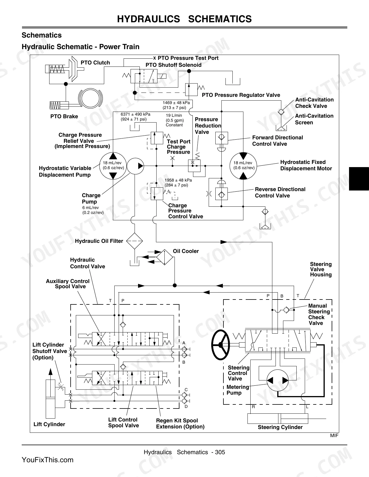
| Hydraulics | 305-328 | Specifications, Schematics, Component Location, Operation and Diagnostics, Tests and Adjustments, Repair |
| Steering | 329-358 | Specifications, Component Location, Power Steering Pump, Steering Control Valve, Power Steering Cylinder, Tie Rod Adjustment, Tests and Adjustments, Repair |
| Brakes | 359-372 | Brake System Component Location, Brake/Differential Linkage (Exploded), Brake System Operation, Brake Problems, Brake/Differential Linkage Adjustment |
| Attachments | 373-424 | Mower Deck Diagnosis, Loader Diagnosis, Mower Deck Belt and Shield, Mower Deck Blade, Mower Deck Spindle, PTO Generator |
| Miscellaneous | 425-436 | Fender Deck Removal and Installation, Fuel Tank Removal and Installation, Headlights Adjustment, Lift Linkage Removal and Installation, Instrument Panel Removal and Installation |
Quick Reference Specifications
| Specification | Value | Page |
|---|---|---|
| All Models | ||
| PTO Ball Switches Torque | 34 N•m (25 lb-ft) | p. 209 |
| Engine Gross Power | 17.9 kW (24 HP) | p. 27 |
| Engine Oil Capacity (w/filter) | 2.8 L (3.0 qt) | p. 27 |
| Cylinder Head Bolts Torque (Lubricating Oil Applied) | 59 - 64 N•m (44 - 47 lb-ft) | p. 34 |
| Battery Voltage | 12V | p. 116 |
| Alternator (Standard) | 20-amp Alternator | p. 116 |
| Transaxle Hydraulic Oil Capacity With Filter | 6.6 L (7.0 qt) | p. 209 |
| Lift Cylinder Bore | 63.5 mm (2.5 in.) | p. 307 |
| Steering Wheel Nut Torque | 38 N•m (28 lb-ft) | p. 331 |
| Brake Adjustment Gap (Pin and Brake Rod Spring Retainer) | 3 - 9 mm (0.12 - 0.35 in.) | p. 361 |
| X400's | ||
| Charge Pump Displacement | 6 cc (0.37 cu.in.)/rev | p. 209 |
| 48-Inch Mower Deck | ||
| 48-Inch Mower Deck Cutting Width | 122 cm (48 in.) | p. 375 |
John Deere X495, X595, X595 4WD DIESEL Common Problems This Manual Covers
Severely clogged transaxle oil filter and hydrostatic transmission slipping or losing forward drive power
Drain the transaxle fluid and replace the restricted oil filter. Fill the system with fresh hydraulic oil to the transaxle hydraulic oil capacity with filter of 6.6 L (7.0 qt) listed on page 209. Bleed the air from the hydrostatic drive and test.
Manual Section: Hydrostatic Transmission Diagnosis p. 209Tractor fails to hold position on inclines when the parking brake pedal is fully depressed
Measure the clearance between the pin and brake rod spring retainer. Adjust the mechanical linkage to achieve the correct brake adjustment gap of 3 - 9 mm (0.12 - 0.35 in.) specified on page 361. Test the pedal engagement to ensure it holds.
Manual Section: Brakes Diagnostics p. 361Frequently Asked Questions
What are the torque specs for the engine mounting bolts on John Deere X495 and X595 tractors?
The engine mounting bolts should be tightened to 63 N•m (47 lb-ft). This specification is found in the engine repair section regarding engine removal and installation. p. 71
What are the replacement specifications for Electrical control module?
If the A2 Control Module fails diagnostic tests, such as not providing voltage at the output or if fuses and links are okay but no voltage is present, the A2 Control Module/Board assembly should be replaced. The manual does not provide specific part numbers or detailed replacement specifications for the module itself. p. 137
How do you fix john Deere X595 momentary PTO switch sticks and triggers a complete engine no-start condition?
Inspect the PTO switch for sticking in the momentary position. Replace the switch and torque the PTO ball switches to 34 N•m (25 lb-ft) as shown on page 209. Verify the electrical control module is not fried from current feedback before attempting to start. p. 209
How do you fix instrument panel is completely dead with no warning lights or display when turning the key?
Remove the instrument panel circuit board and inspect for solder joint cracks. Check the pin connections using a multimeter to verify steady 12V battery voltage. Refer to the wiring diagram to trace the power circuit if the display remains completely dead.
How quickly can I access this manual?
You get a 446-page searchable PDF that downloads instantly after checkout. Open it on your laptop, tablet, or phone, and bring it right to the shop floor.
Is this John Deere X495, X595, X595 4WD Diesel Technical Manual printable?
Yes. The PDF has no DRM restrictions, so print any page or section you need for your shop. Works with any standard printer.
Are there wiring harness diagrams in this John Deere X495, X595, X595 4WD?
Yes. You'll find an electrical wiring diagram covering the main wiring layout.


Reviews
There are no reviews yet.