Part of the John Deere Repair Manuals.
Whether you are turning wrenches on a John Deere 1350, 1550, 1750, 1850, 1850N, 1950, 1950N, 2250, 2450, 2650, 2650N, 2850, 3050, 3350, or 3650 tractor, this 591-page John Deere 2850 technical manual PDF (OEM #TM4446) holds the exact factory instructions to fix it right the first time. Inside, you get complete electrical diagrams for non-cab models, full hydraulic schematics for the hydrostatic steering, and step-by-step troubleshooting for the dual-stage engine clutch. Open to any chapter to find exploded views of the power train, selective control valves, and SG2 cab ventilation systems. Adjust the single-stage engine clutch linkages to a precise 30 mm free play and verify the hydrostatic steering pump output hits 15 MPa at operating temperature. Stop throwing expensive parts at a sluggish rockshaft. Download this bookmarked file right to your tablet, search for the exact spec you need, and get that tractor back in the dirt.
What's Inside This John Deere 1350 to 3650 Series Manual
| System | Pages | Key Topics |
|---|---|---|
| Safety | 5-14 | Prepare for Emergencies, Work in Ventilated Area, Use Proper Lifting Equipment, Handle Fluids Safely, Avoid High-Pressure Fluids, Prevent Battery Explosions |
| Engine | 15-24 | Radiator and Viscous Fan Drive (Specifications, Function of Radiator Cap: Tractors with Expansion Tank, Function of Radiator Cap: Tractors Without Expansion Tank) |
| Fuel and Air Intake System | 25-34 | 05 - Fuel Tank, Auxiliary Fuel Tank and Water Trap, 10 - Cold Weather Starting Aids, 15 - Speed Control Linkage, 20 - Air Cleaner |
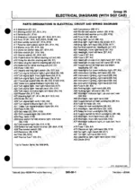
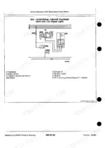
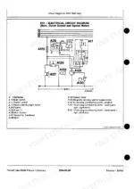
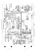
| Electrical Diagrams (Without Cab) | 45-74 | 05 - General, 10 - Electrical Diagrams (Without Cab) |
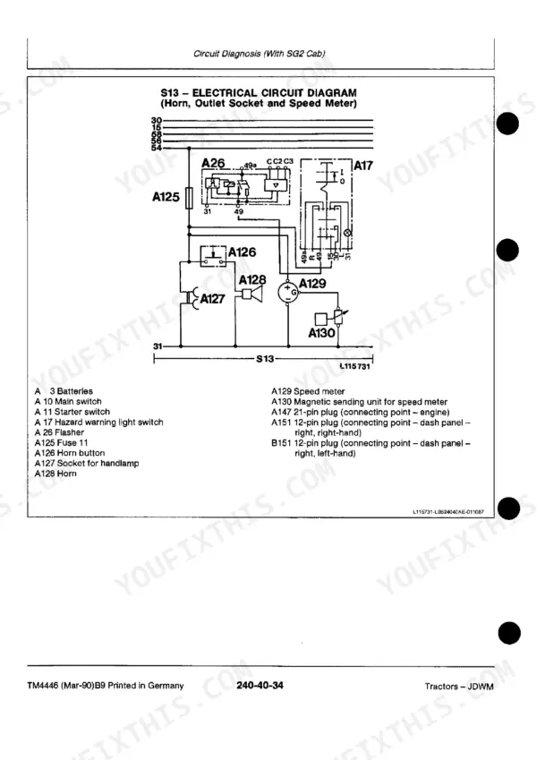
| Circuit Diagnosis (Without Cab) | 75-101 | 15 - Circuit Diagnosis (Without Cab) |
| Electrical Diagrams (with MC1 Cab) | 102-120 | 20 - Sealed-Beam Lighting Equipment (See Ctm-4459), 25 - Electrical Diagrams (with MC1 Cab) |
| Circuit Diagnosis (with MC1 Cab) | 121-157 | 30 - Circuit Diagnosis (with MC1 Cab) |
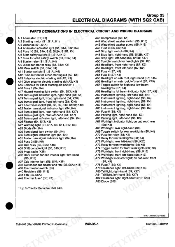
| Electrical Diagrams (with SG2 Cab) | 158-186 | 35 - Electrical Diagrams (with SG2 Cab) |
| Circuit Diagnosis (with SG2 Cab) | 187-229 | 40 - Circuit Diagnosis (with SG2 Cab) |
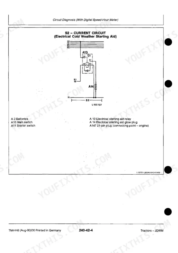
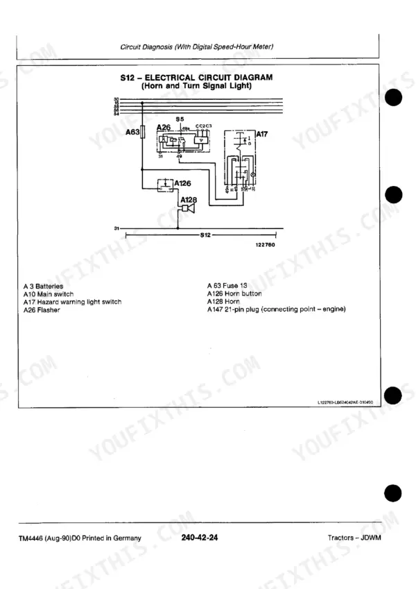
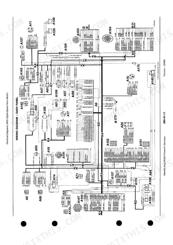
| Circuit Diagnosis (with Digital Speed-Hour Meter) | 230-277 | 41 - Electrical Diagrams (with Digital Speed-Hour Meter) |
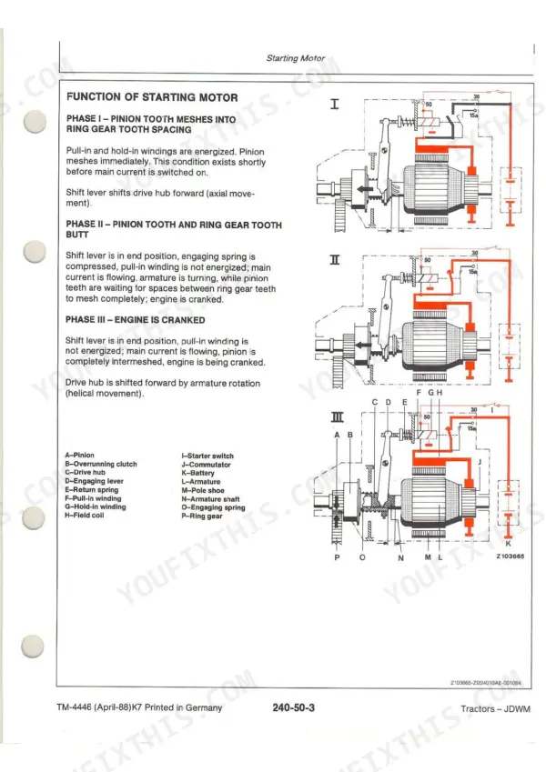
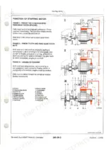
| Alternator | 278-293 | 45 - Testing Components, 50 - Starting Motor, 55 - Alternator |
| Power Train | 294-398 | 05 - Clutch Operating Linkages, 10 - Single-Stage Engine Clutch, 15 - Dual-Stage Engine Clutch, 20 - Hi-Lo Shift Unit, 25 - Creeper Transmission |
| Steering System and Brakes | 399-445 | 05 - Hydrostatic Steering, 10 - Power Steering, 15 - Manual Steering, 20 - Hydraulic Brakes, 25 - Handbrake, 30 - Hydraulic Trailer Brake |
| Hydraulic System | 446-547 | 05 - Operation and Tests, 10 -Valves, Filters, Oil Cooler and Oil Reservoir, 15 - Hydraulic Pumps, 20 - Rockshaft, 25 - Front Hitch, 30 - Selective Control Valves (Spool Type) |
| Operator'S Cabs | 548-591 | 05 - Air Conditioning System, 10 - Cab Ventilation and Heating System - SG2 Cab, 15 - Cab Ventilation and Heating System - MC1 Cab |
Quick Reference Specifications
| Specification | Value | Page |
|---|---|---|
| Transmission shift linkages | 30 | p. 2 |
| Fuel tank, auxiliary fuel tank and water trap | 05 | p. 2 |
| Hydraulic pumps | 15 | p. 3 |
| Electrical diagrams (without cab) | 10 | p. 2 |
| Circuit diagnosis (without cab) | 15 | p. 2 |
| Starting motor minimum solenoid voltage | 8 volts | p. 290 |
| Alternator voltage (engine off) | 12 volts | p. 292 |
| Alternator voltage (increasing engine speed) | 13.7 to 14.5 volts | p. 292 |
| Hydrostatic creeper transmission system oil pressure | 19000 kPa (190 bar; 2760 psi) | p. 325 |
| Hydrostatic steering shock valves adjustment pressure | 21000 kPa (210 bar; 3050 psi) | p. 402 |
John Deere 1350 to 3650 Series Common Problems This Manual Covers
Lower range shaft bearing failure with whining noise that changes pitch under load
Drain the transmission housing and check oil level and condition first; contaminated or low oil accelerates bearing wear. Remove the range shaft and rotate the bearings by hand, feeling for roughness, play, or grinding. Replace any bearing showing radial play beyond spec and repack with the correct gear oil before reinstalling the shaft.
Manual Section: 250 - Power Train p. 294Fuel pump wear causing rough idle, hard starting, or power loss under load
Check the fuel tank and water trap assembly for contamination or a clogged strainer before condemning the pump; reference page 25 for the fuel tank and water trap layout. Test fuel pump output pressure at idle and at rated RPM against spec, and inspect the delivery valve for wear. Replace the pump if pressure drops off under load or fluctuates at steady RPM.
Manual Section: 230 - Fuel and Air Intake System p. 25Hi-Lo shift unit jumps out of engagement or shifts slowly under load
Check the Hi-Lo shift unit malfunction chart to isolate whether the fault is oil pressure or mechanical linkage. Verify system oil pressure at the test port and compare against the hydrostatic creeper transmission spec of 19000 kPa (190 bar; 2760 psi) on page 325 as a baseline for the circuit. Inspect the shift fork and detent spring for wear if pressure reads within spec.
Manual Section: 250 - Power TrainHydrostatic steering hard to turn with vibration felt through the wheel
Check the hydrostatic steering malfunction chart on page 412 to narrow down whether the cause is pump, valve, or cylinder related. Test the shock valve adjustment pressure against the spec of 21000 kPa (210 bar; 3050 psi) on page 402, adjusting the relief setting if it reads low. Inspect the steering cylinder rod for scoring that could cause internal bypass and vibration.
Manual Section: 260 - Steering System and Brakes p. 412Intermittent electrical fault with gauges or lights cutting out over rough terrain
Start with the electrical circuit malfunction diagnosis to test for high resistance, open, or grounded circuits before replacing components. Pull the wiring diagram and pin assignment reference on page 35 to trace the affected circuit back to its connector. Check every connector in that run for corrosion or a loose pin, and clean or repin as needed rather than replacing the harness outright.
Manual Section: 240 - Electrical System p. 35Frequently Asked Questions
What fluids and capacities does this machine require for the air conditioning system?
The air conditioning system requires R-12 refrigerant with a capacity of 1.8 kg (4 lb). For the compressor, a full charge of Frigidaire oil 525 or Reniso type KM oil is needed, with a capacity of 312 cm³ (11 fl.oz.). p. 550
How do you fix john Deere 1550 transmission selector wear causing gear sli
Pull the shift cover and inspect the selector forks and detent balls for scoring or rounded edges; replace any worn selectors rather than trying to shim them. Reference the transmission shift linkages specs on page 30 for correct linkage adjustment before reassembly. Road test in every gear to confirm clean engagement with no jump-out. p. 294
Do I get instant access to this John Deere 1350 Technical Manual?
A 591-page Technical Manual in searchable PDF format (34 MB), available the moment you complete checkout. View on computer, tablet, or phone, with no shipping wait.
Is printing allowed for this John Deere 1350 Technical Manual?
Yes. Print a chapter or just the pages for the job at hand, for use in your own shop. Any home or office printer works.
Does this John Deere 1350 Technical Manual include the hydraulic layout?
A hydraulic system diagram for the John Deere 1350, 1550, 1750, 1850, 1850N, 1950, 1950N, 2250, 2450, 2650, 2650N, 2850, 3050, 3350, 3650 is included.