
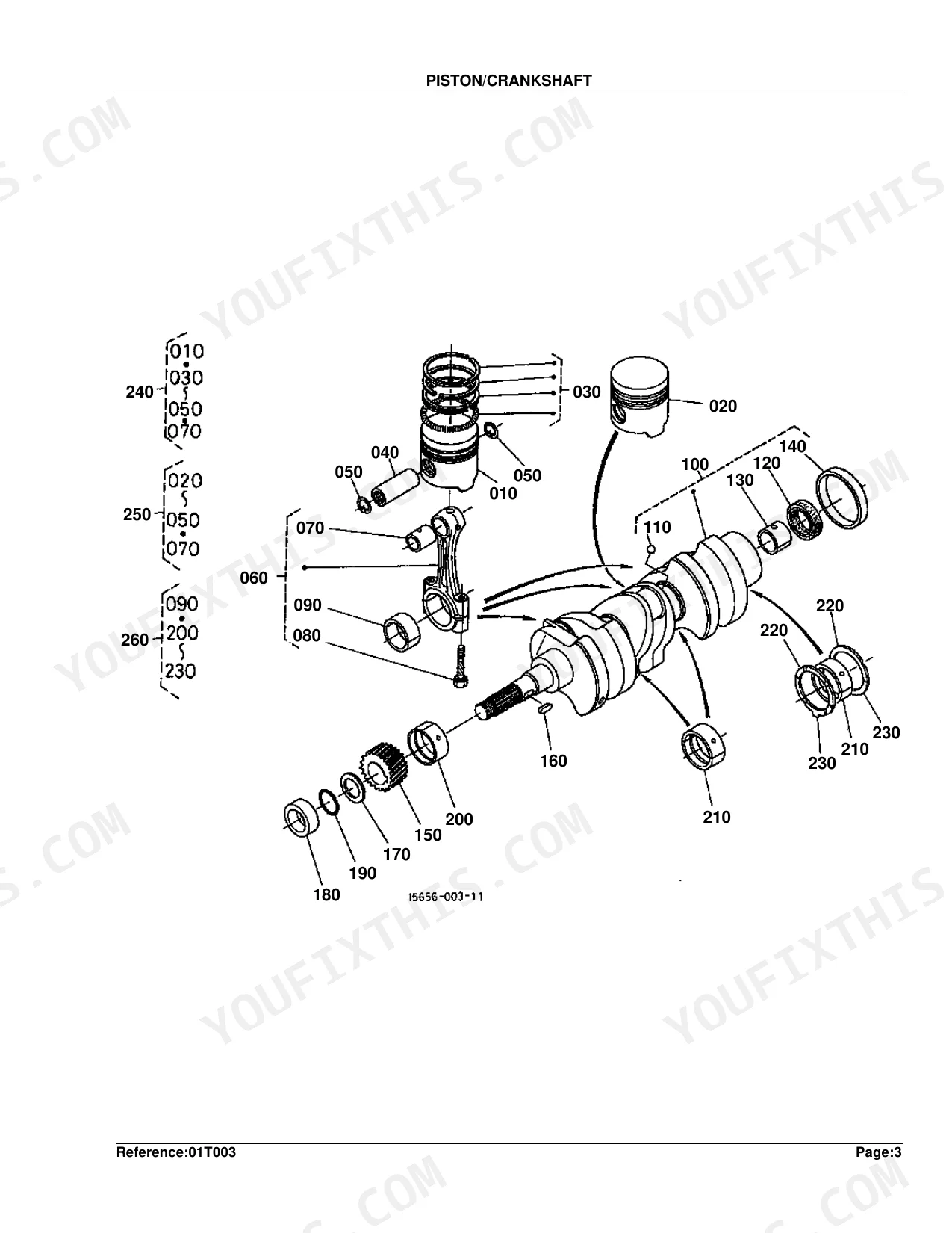
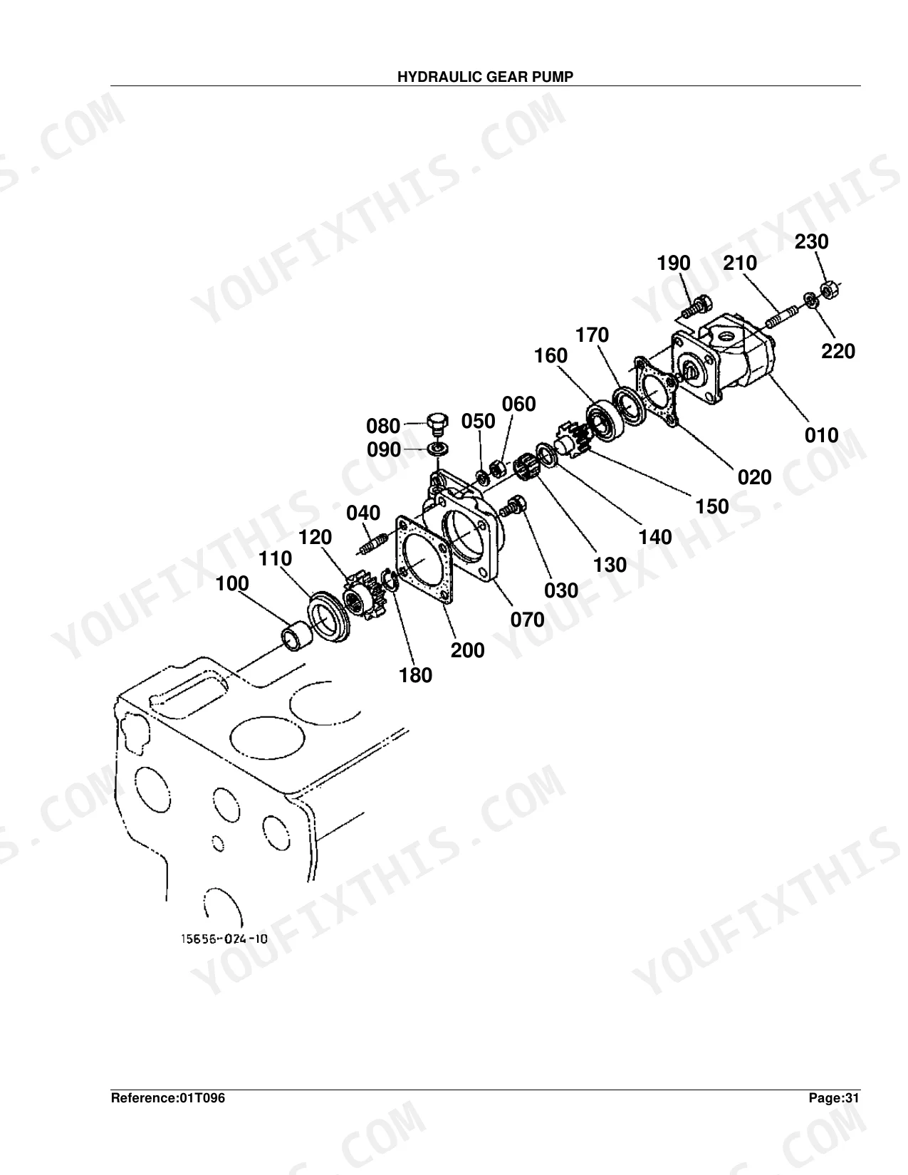
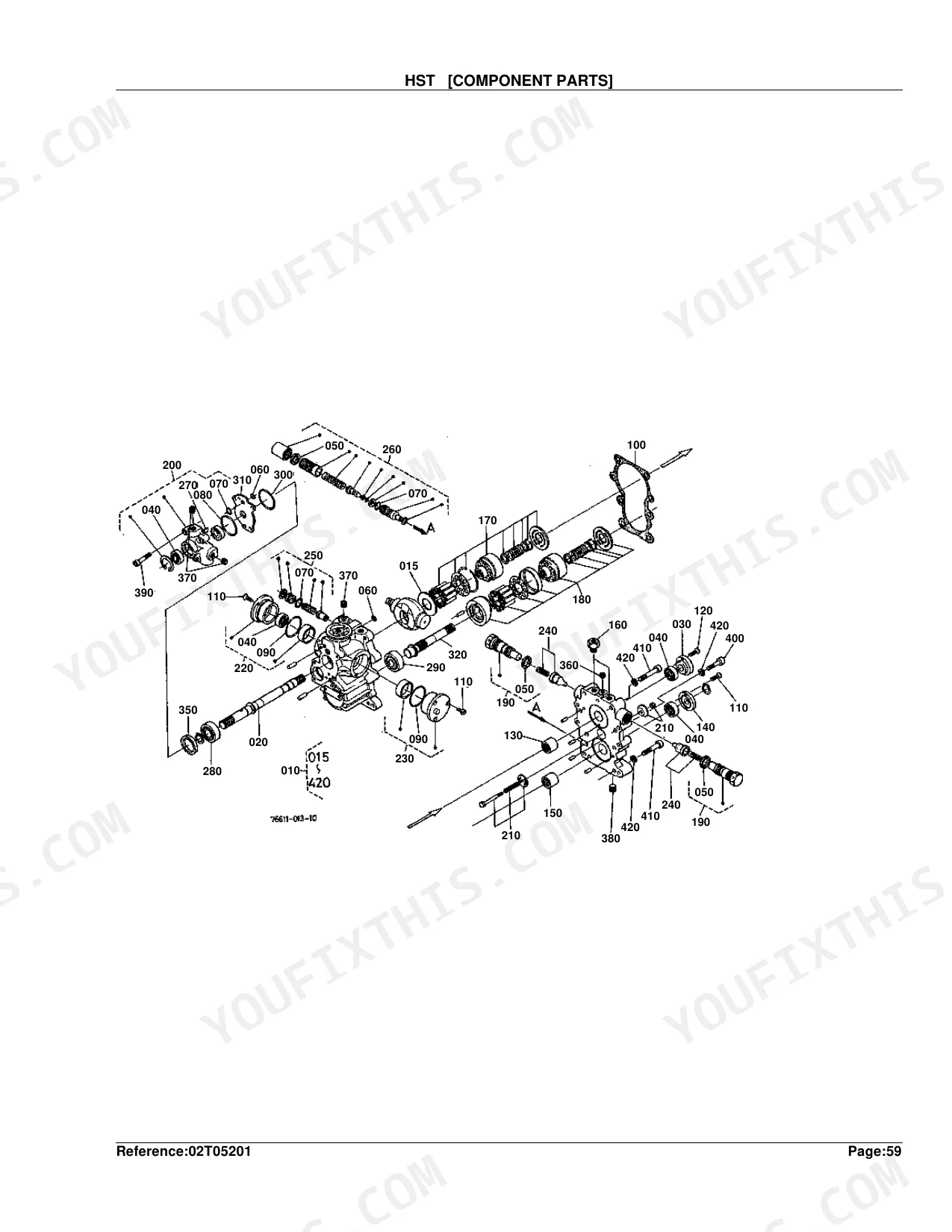
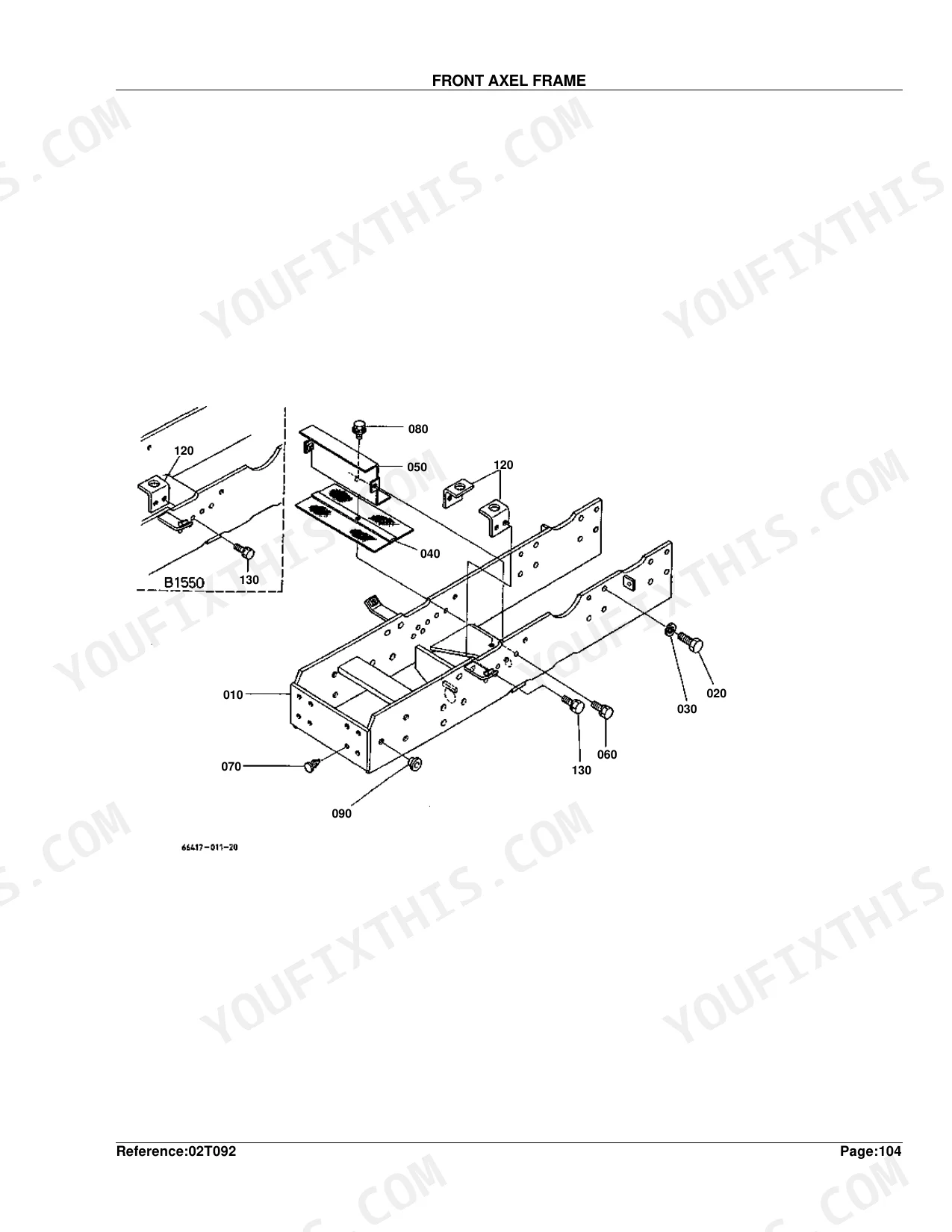
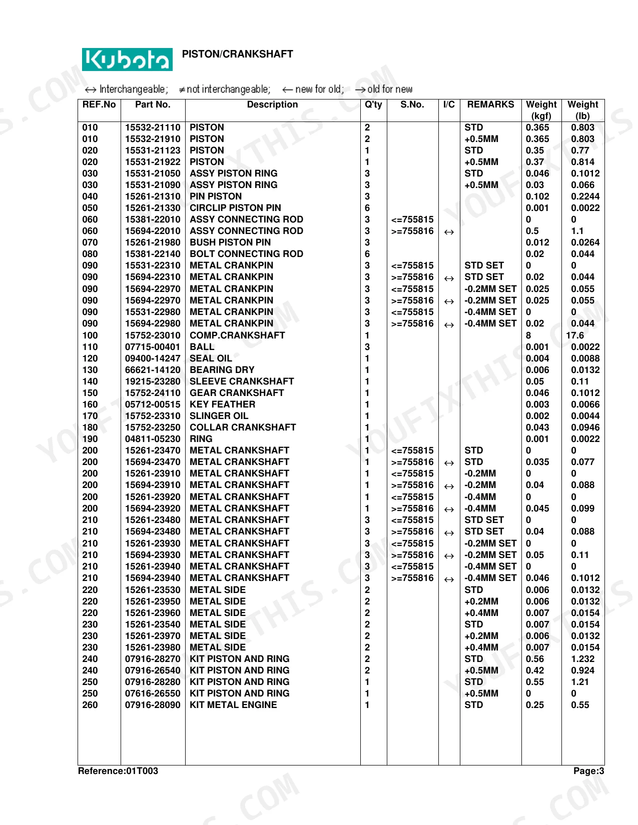
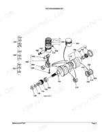
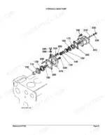
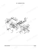
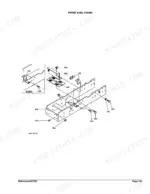
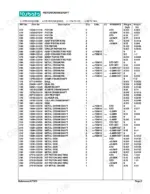
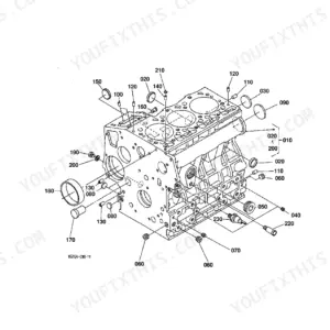
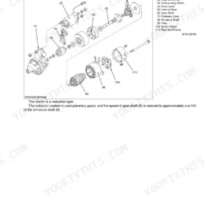
Order the wrong part once and you've lost a half-day. This Kubota B1750HST-D Parts Catalog runs 304 pages built to stop that: 56 pages on engine parts from crankcase through governor, more than 160 pages of drivetrain breakdowns covering the clutch, HST unit, transmission, axles, and PTOs at component level, and 20 pages of hydraulic diagrams mapping the pump, control valve, lift arm, and full pipe routing for both power and manual steering circuits. Hunting a nozzle holder sub-component, the 27-tooth hydraulic pump gear, a +0.5MM piston oversize or -0.2MM crankpin bearing undersize? Exploded views and factory part numbers cover every assembly. Download once, then use the by-system bookmarks to jump straight to HST component parts or bi-speed turn hardware on any device.
What's Inside This Kubota B1750HST-D Parts Manual
| System | Pages |
|---|---|
| Crankcase | 6-7 |
| Oil Pan | 8-10 |
| Piston/Crankshaft | 11-12 |
| Main Bearing Case | 13-14 |
| Flywheel | 15-17 |
| Cylinder Head | 18-19 |
| Valve/Rocker Arm | 20-21 |
| Nozzle Holder | 22-23 |
| Nozzle Holder [Component Parts] | 24-25 |
| Cylinder Head Cover | 26-28 |
| Inlet Manifold | 29-30 |
| Exhaust Manifold | 31-32 |
| Camshaft | 33-34 |
| Gear Case | 35-36 |
| Water Pump | 37-38 |
| Water Flange | 39-40 |
| Fuel Pump | 41-42 |
| Injection Pump | 43-44 |
| Injection Pump [Component Parts] | 45-46 |
| Engine Stop Lever | 47-48 |
| Speed Control Plate | 49-50 |
| Governor | 51-52 |
| Upper Gasket Kit | 53-54 |
| Lower Gasket Kit | 55-56 |
| Dynamo [A] [Au] [Nz] | 57-58 |
| Dynamo [A] [Au] [Nz] [Component Parts] | 59-60 |
| Clutch | 61-62 |
| Hydraulic Gear Pump | 63-64 |
| Hydraulic Gear Pump [Component Parts] | 65-67 |
| Air Cleaner | 68-69 |
| Muffler | 70-71 |
| Horizontal Muffler [Option] | 72-73 |
| Engine Stop Rod | 74-76 |
| Accelerator Lever | 77-78 |
| Fuel Tank | 79-80 |
| Fuel Pipe | 81-82 |
| Fuel Filter [Component Parts] | 83-84 |
| Water Pipe | 85-86 |
| Radiator | 87-88 |
| Starter | 89-90 |
| Starter [Component Parts] | 91-92 |
| Battery | 93-95 |
| Light | 96-98 |
| Working Light [Option] | 99-100 |
| Panel/Switch [A] [Au] [Nz] | 101-103 |
| Panel Board [Component Parts] | 104-105 |
| Wire Harness [A] [Au] [Nz] | 106-107 |
| Clutch Rod | 108-109 |
| Clutch Pedal | 110-111 |
| Clutch Housing | 112-114 |
| Transmission Case | 115-116 |
| Transmission Case Cover | 117-118 |
| HST | 119-121 |
| HST [Component Parts] | 122-127 |
| Propeller Shaft | 128-129 |
| 2Nd Shaft | 130-131 |
| 3Rd Shaft/5Th Shaft | 132-133 |
| 4Th Shaft | 134-135 |
| Front Wheel Drive Shaft | 136-137 |
| Rear PTO | 138-140 |
| Mid PTO | 141-142 |
| Front PTO [Option] | 143-144 |
| Neutral Holder | 145-147 |
| Speed Control Pedal | 148-149 |
| Speed Change Plate | 150-151 |
| Speed Set Lever | 152-153 |
| Range Gear Shift Lever | 154-155 |
| PTO Gear Shift Lever | 156-157 |
| Rear Differential | 158-159 |
| Diff. Lock Pedal | 160-161 |
| Rear Axle | 162-163 |
| Rear Axle Case | 164-165 |
| Rear Wheel (8-16) | 166-168 |
| Rear Wheel (9.5-16) | 169-171 |
| Rear Wheel (31 X 13.5-15) | 172-174 |
| Rear Wheel (31 X 13.5-15 Bar) [A] | 175-177 |
| Brake | 178-179 |
| Brake Rod | 180-181 |
| Brake Pedal | 182-183 |
| Front Wheel Hub | 184-185 |
| Front Gear Case | 186-187 |
| Bevel Gear Case | 188-189 |
| Front Axle Case [Without Bi-Speed Turn] | 190-191 |
| Front Axle Case [With Bi-Speed Turn] | 192-193 |
| Front Differential [Without Bi-Speed Turn] | 194-196 |
| Front Differential [With Bi-Speed Turn] | 197-198 |
| Bevel Gear [With Bi-Speed Turn] | 199-200 |
| Clutch Disk [With Bi-Speed Turn] | 201-202 |
| Front Drive Shaft | 203-205 |
| Front Drive Lever | 206-207 |
| Shift Fork [With Bi-Speed Turn] | 208-210 |
| Shift Lever [With Bi-Speed Turn] | 211-212 |
| Bi-Speed Turn Rod [With Bi-Speed Turn] | 213-214 |
| Bi-Speed Turn Lever [With Bi-Speed Turn] | 215-216 |
| Front Wheel (6-12B) | 217-218 |
| Front Wheel (6-12) | 219-220 |
| Front Wheel (20.5 X 8.00-10) | 221-222 |
| Front Axel Frame | 223-225 |
| Knuckle Arm [Without Bi-Speed Turn] | 226-227 |
| Knuckle Arm [With Bi-Speed Turn] | 228-229 |
| Manual Steering | 230-232 |
| Power Steering | 233-234 |
| Manual Steering [Component Parts] | 235-236 |
| Power Steering [Component Parts] | 237-238 |
| Hydraulic Pipe (Ps) | 239-240 |
| Hydraulic Pipe (Front) | 241-242 |
| Hydraulic Pipe (Rear) | 243-244 |
| Hydraulic Block (Ms) [Component Parts] | 245-246 |
| Hydraulic Block (Ps) [Component Parts] | 247-248 |
| Hydraulic Pipe (HST) | 249-250 |
| Oil Cooler | 251-252 |
| Lift Arm | 253-255 |
| Hyd.Cylinder Cap [Component Parts] | 256-261 |
| Control Valve | 262-263 |
| Control Valve [Component Parts] | 264-266 |
| Top Link | 267-268 |
| Lower Link | 269-270 |
| Lift Rod | 271-272 |
| Hood (Bonnet) | 273-274 |
| Lace | 275-276 |
| Hood Cover Rear | 277-278 |
| Skirt (Front) | 279-280 |
| Skirt (Side) | 281-283 |
| Dust Cover | 284-285 |
| Tank Support | 286-287 |
| Fender | 288-290 |
| Seat | 291-292 |
| Step | 293-294 |
| ROPS [A] [Ca] | 295-298 |
| Label 1 | 299-300 |
| Label 2 | 301-303 |
| Accessories and Service Parts | 304-304 |
Quick Reference Specifications
| Specification | Value | Page |
|---|---|---|
| Amperage | 15A | p. 107 |
| Piston Oversize | +0.5MM | p. 12 |
| Crankpin Metal (Bearing) Undersize | -0.2MM SET | p. 12 |
| Nozzle Adjusting Washer Thickness | 1.95MM | p. 25 |
| Hydraulic Pump Gear Tooth Count | 27T | p. 64 |
| Fuse Rating | 15A | p. 107 |
| 2nd Shaft Gear Tooth Count | 14T | p. 131 |
| 3rd Shaft Gear Tooth Count | 21T | p. 133 |
| 4th Shaft Gear Tooth Count | 24T | p. 135 |
| Rear Differential Bevel Gear Ratio | 6-37T | p. 159 |
| Manual Steering Adjusting Collar Thickness Range | 1.515 TO 1.535MM | p. 236 |
| Front Differential Shim Thickness | 0.5MM | p. 196 |
Kubota B1750HST-D Common Problems This Manual Covers
Kubota B1750HST-D no-start, need part numbers for blown fuse, relay, and key switch p. 101
Open the Panel/Switch exploded view on page 101 to locate the key switch and relay assemblies with their part numbers. Cross-reference the Wire Harness diagram on page 106 for connector and fuse holder positions. The fuse in this system is rated at 15A (page 107); verify the rating before ordering a replacement.
Manual Section: Panel/Switch [A] [Au] [Nz]HST transmission slipping under load, need internal component part numbers for correct rebuild kit p. 119
Confirm your unit's configuration in the HST overview on page 119, then work through the HST [Component Parts] breakdown on page 122, which lists pistons, valves, and seal assemblies with individual part numbers. Cross-reference the 2nd Shaft diagram on page 130; the 14-tooth gear listed there (page 131) confirms you are ordering for the correct drivetrain build.
Manual Section: HST [Component Parts]Hydraulic gear pump internal parts needed, unsure which rebuild kit and gear assembly matches this machine p. 63
Pull the Hydraulic Gear Pump diagram on page 63 to identify the pump assembly and housing part numbers. The Component Parts breakdown on pages 65-67 lists individual gears, seals, and end plates separately. The pump gear in this manual has a 27-tooth count (page 64); confirm this matches your pump before ordering any gear set or seal kit.
Manual Section: Hydraulic Gear Pump [Component Parts]Engine cranks but won't fire, need fuel shut-off solenoid and injection system component part numbers p. 47
Check the Engine Stop Lever diagram on page 47 and Engine Stop Rod on page 74 for fuel shut-off solenoid and linkage part numbers. For injection components, the Nozzle Holder [Component Parts] on page 24 breaks down the full injector assembly; the nozzle adjusting washer listed there measures 1.95MM (page 25), so include it when ordering a nozzle rebuild.
Manual Section: Engine Stop LeverRear differential making noise, need to identify bevel gear, pinion, and axle component part numbers p. 158
Locate the Rear Differential exploded view on page 158 to identify gear set and carrier components. The bevel gear set in this manual runs a 6-37 tooth ratio (page 159); confirm this matches your machine before ordering. Cross-reference the Rear Axle section on page 162 and Rear Axle Case on page 164 for bearing and housing part numbers.
Manual Section: Rear DifferentialFrequently Asked Questions
What are the replacement specifications for fuel shut-off solenoid?
The fuel shut-off solenoid is the SOLENOID STOP, part number 15471-60010. You'll find it as reference number 010 in the ENGINE STOP ROD assembly.
What are the replacement specifications for fuses?
The fuse is the FUSE AUTO, part number 35820-75560, rated 15A. The tractor uses two of them.
What do I get after purchasing this Kubota B1750HST-D manual?
Immediate download of the complete 304-page searchable Parts Catalog. Open it on any device, laptop at your desk or phone out in the field.
Are there any print restrictions on this Kubota B1750HST-D manual?
Yes, print as many copies as you want; there are no restrictions. Plenty of mechanics print just the section they need and carry it to the shop floor.
Document Quality
This is a scanned parts catalog for the Kubota B1750HST-D, and you can search the full text thanks to an accurate OCR layer. The text in the parts lists is clear and easy to read, while the exploded-view diagrams are raster images that are generally legible, though they can become pixelated when zoomed in. The pages are clean, with minimal scan artifacts or marks, providing a good overall viewing experience.


Reviews
There are no reviews yet.