
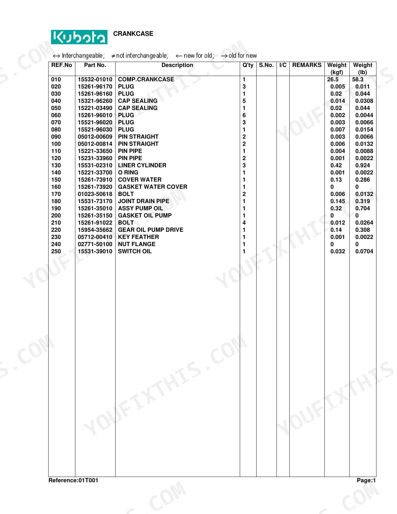


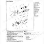
Every exploded-view diagram and part number for the B20 compact tractor sits in these 251 pages, from the crankcase back to the ROPS. The catalog runs over 120 illustrated parts lists, with callout numbers tied to genuine Kubota part numbers and breakdowns of the engine, HST drivetrain, hydraulic lift, chassis, and cab assemblies. Flip to the injection pump or control valve and each component is numbered, named, and ready to cross-reference. Ordering pistons? Standard bore takes a +0.5mm oversize, the crankpin metal runs to a -0.2mm undersize, and the nozzle holder adjusting washers range from 1.00mm to 1.95mm. No more squinting at a worn parts decal or ordering the wrong bushing twice. Bookmarks are set by system, so you jump straight to the assembly you're rebuilding and pull the exact number.
What's Inside This Kubota B20 Parts Manual
| System | Pages |
|---|---|
| Crankcase | 6-7 |
| Oil Pan | 8-9 |
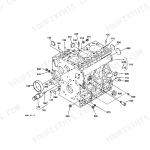
| Piston/Crankshaft | 10-11 |
| Main Bearing Case | 12-13 |
| Flywheel | 14-15 |
| Cylinder Head | 16-17 |
| Valve/Rocker Arm | 18-19 |
| Nozzle Holder | 20-21 |
| Nozzle Holder [Component Parts] | 22-23 |
| Cylinder Head Cover | 24-25 |
| Inlet Manifold | 26-27 |
| Exhaust Manifold | 28-29 |
| Camshaft | 30-31 |
| Gear Case | 32-33 |
| Water Pump | 34-35 |
| Water Flange/Thermostat | 36-37 |
| Fuel Camshaft | 38-39 |
| Injection Pump | 40-41 |
| Injection Pump [Component Parts] | 42-43 |
| Engine Stop Lever | 44-45 |
| Speed Control Plate | 46-47 |
| Governor | 48-49 |
| Fan | 50-51 |
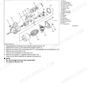
| Dynamo | 52-53 |
| Dynamo [Component Parts] | 54-55 |
| Clutch | 56-57 |
| Hydraulic Gear Pump | 58-59 |
| Hydraulic Gear Pump [Component Parts] | 60-61 |
| Air Cleaner | 62-63 |
| Muffler | 64-65 |
| Engine Stop Rod | 66-67 |
| Accelerator Lever | 68-69 |
| Release Lever | 70-71 |
| Fuel Tank | 72-73 |
| Fuel Pipe 1 | 74-75 |
| Fuel Filter [Component Parts] | 76-77 |
| Fuel Pipe 2 | 78-79 |
| Water Pipe | 80-81 |
| Radiator | 82-83 |
| Starter | 84-85 |
| Starter [Component Parts] | 86-87 |
| Battery | 88-89 |
| Light | 90-91 |
| Panel/Switch | 92-93 |
| Wire Harness | 94-95 |
| Clutch Rod | 96-97 |
| Clutch Pedal | 98-99 |
| Clutch Housing | 100-101 |
| Transmission Case | 102-103 |
| Transmission Case Cover | 104-105 |
| HST | 106-107 |
| HST [Component Parts] | 108-110 |
| Propeller Shaft | 111-112 |
| 1St Shaft/2Nd Shaft | 113-114 |
| 3Rd Shaft | 115-116 |
| 4Th Shaft | 117-118 |
| Front Drive Shaft/6Th Shaft | 119-120 |
| 7Th Shaft | 121-122 |
| PTO Shaft | 123-124 |
| Neutral Holder | 125-126 |
| Speed Control Pedal | 127-128 |
| Speed Change Plate | 129-130 |
| Hi-Lo Gear Shift Lever | 131-132 |
| Hi-Lo Gear Shift Fork | 133-134 |
| Front Wheel Drive Lever/PTO Lever | 135-136 |
| Front Drive Fork | 137-138 |
| PTO Fork Shaft | 139-140 |
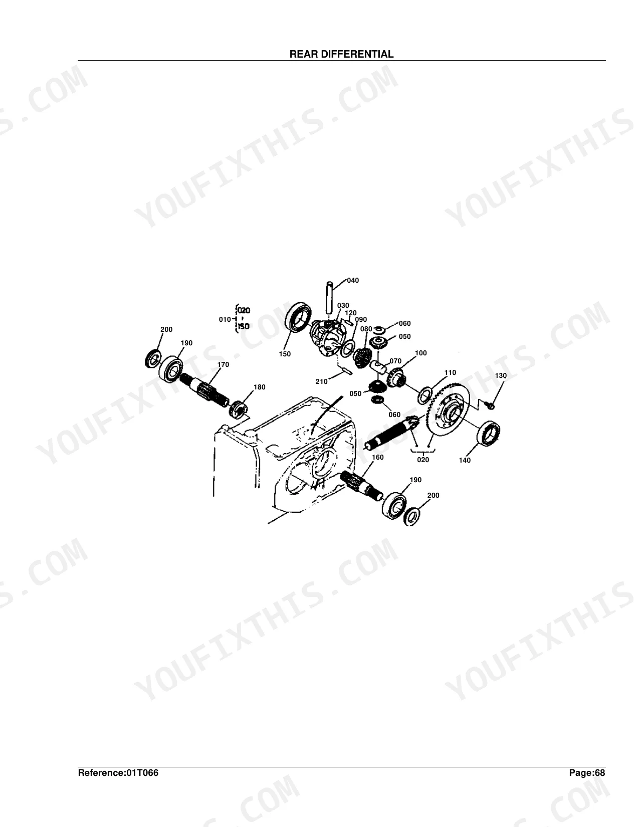
| Rear Differential | 141-142 |
| Diff.Lock Pedal | 143-144 |
| Rear Axle | 145-146 |
| Rear Axle Case | 147-148 |
| Rear S.S. Sure Grip Tire (12.4-16) | 149-150 |
| Rear Ind.Sure Grip Tire (12.4-16) (Option) | 151-152 |
| Brake | 153-154 |
| Brake Rod | 155-156 |
| Brake Pedal | 157-158 |
| Bevel Gear Shaft | 159-160 |
| Front Axle Case | 161-162 |
| Bevel Gear Case | 163-164 |
| Front Axle Arm | 165-166 |
| Front Differential | 167-168 |
| Front Drive Shaft | 169-170 |
| Front Sure Grip Tire (23 X 8.50-12) | 171-172 |
| Front Axle Frame | 173-174 |
| Main Frame | 175-176 |
| Knuckle Arm/Tie Rod | 177-178 |
| Power Steering | 179-180 |
| Power Steering [Component Parts] | 181-183 |
| Hydraulic Pipe (Ps) | 184-185 |
| Hydraulic Gear Pump (Front) | 186-187 |
| Hydraulic Gear Pump (Front) [Component Parts] | 188-189 |
| Hydraulic Pipe (Suction) | 190-191 |
| Hydraulic Pipe (Delivery) | 192-193 |
| Hydraulic Pipe (Return) | 194-195 |
| Hydraulic Block [Component Parts] | 196-197 |
| Hydraulic Pipe (Charge) | 198-199 |
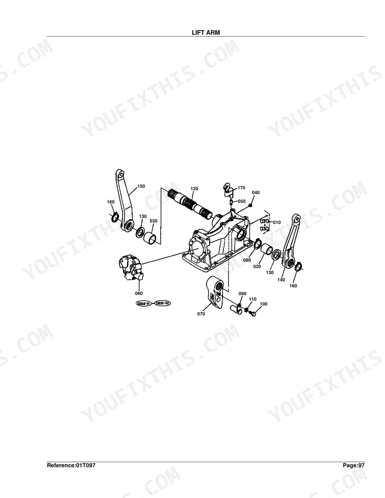
| Lift Arm | 200-201 |
| Hyd.Cylinder Cap [Component Parts] | 202-203 |
| Control Valve | 204-205 |
| Control Valve 1 [Compornent Parts] | 206-207 |
| Control Valve 2 [Compornent Parts] | 208-209 |
| Control Valve 3 [Compornent Parts] | 210-211 |
| Top Link | 212-213 |
| Lower Link / Lift Rod | 214-215 |
| Check Chain | 216-217 |
| Top Link Bracket | 218-219 |
| Hood (Bonnet) | 220-221 |
| Hood Cover Rear | 222-223 |
| Front Grille | 224-225 |
| Fender | 226-227 |
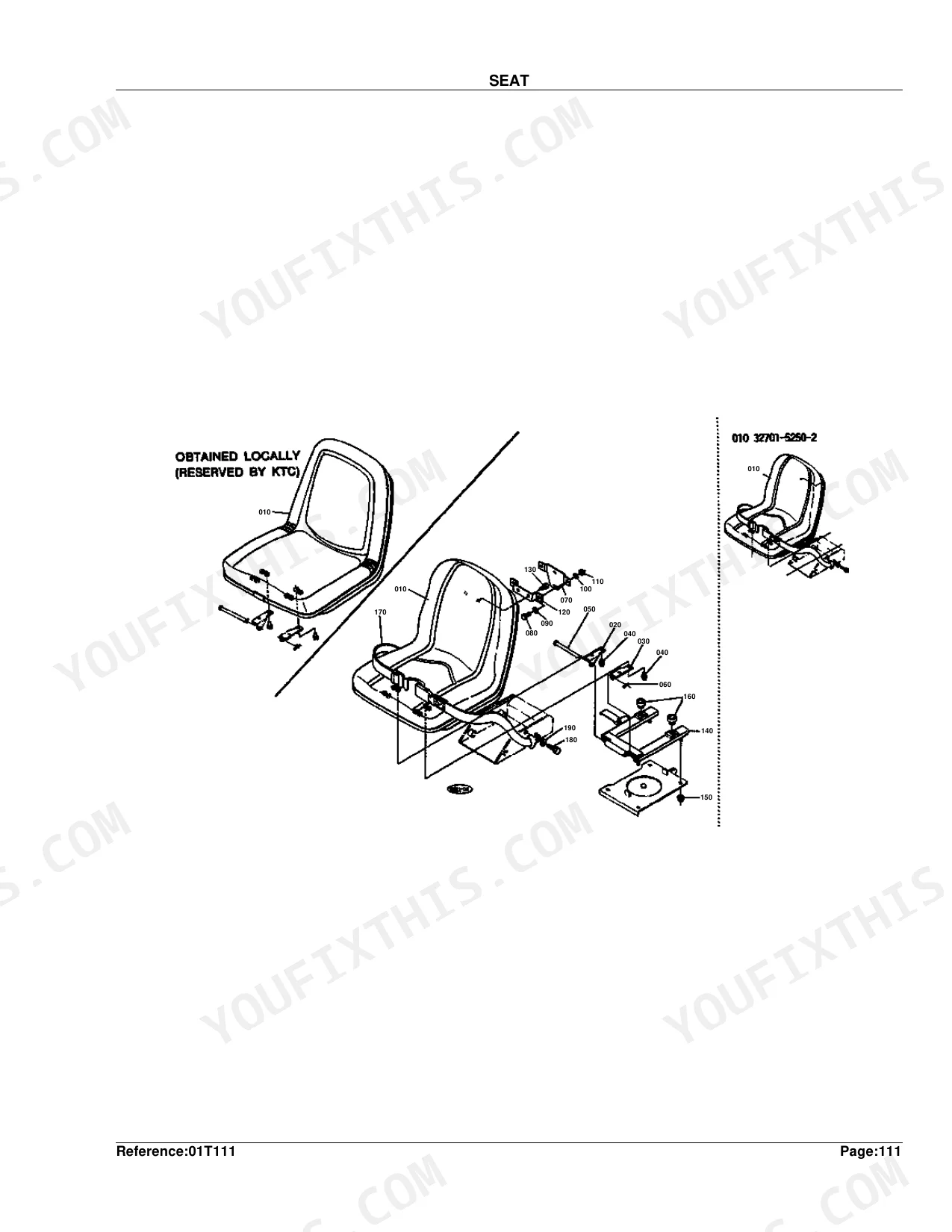
| Seat | 228-229 |
| Seat Turn Table | 230-231 |
| Seat Base | 232-233 |
| Seat Plate | 234-235 |
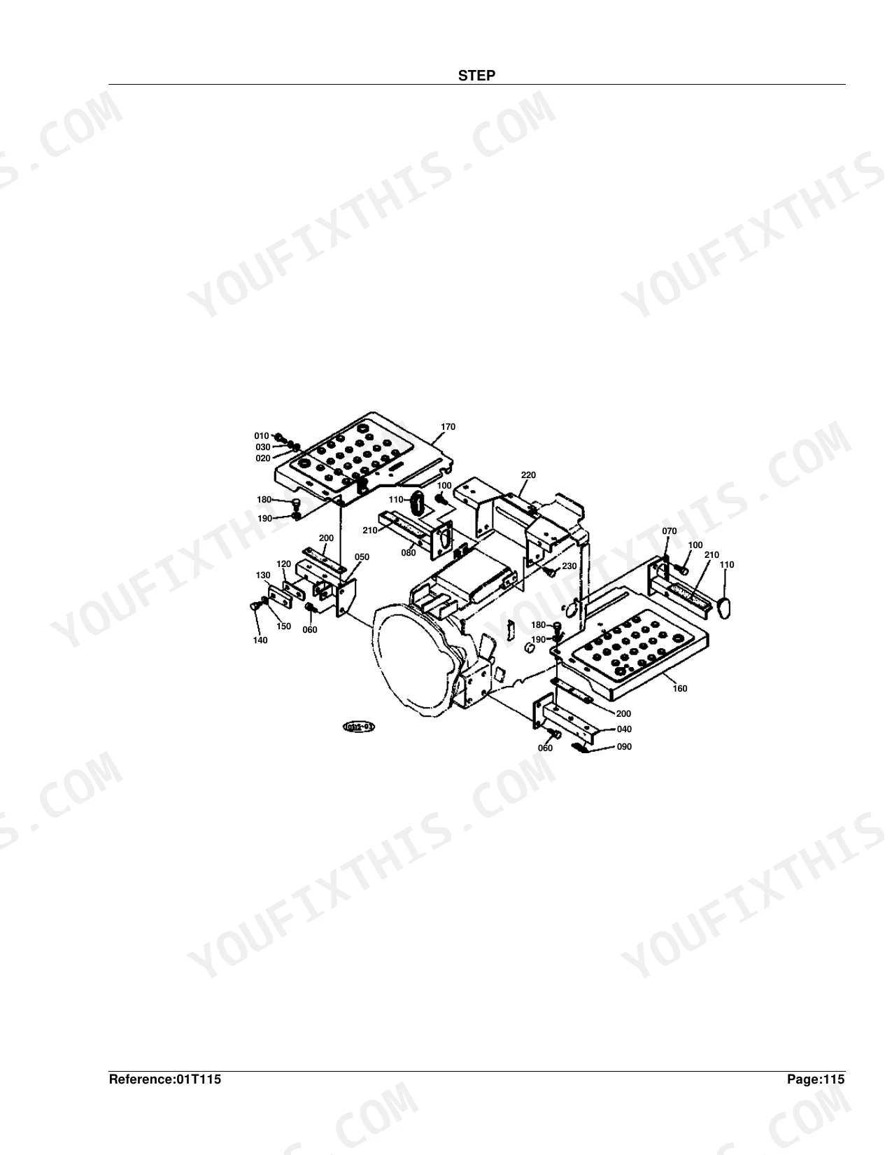
| Step | 236-237 |
| ROPS | 238-239 |
| Rear Working Light [Option] | 240-241 |
| Front Working Light [Option] | 242-243 |
| FOPS [Option] | 244-245 |
| Label 1 | 246-247 |
| Label 2 | 248-250 |
| Accessories and Service Parts | 251-251 |
Quick Reference Specifications
| Specification | Value | Page |
|---|---|---|
| Fuse Rating | 15A | p. 95 |
| Piston Oversize | +0.5MM | p. 11 |
| Metal Crankpin Undersize | -0.2MM | p. 11 |
| Nozzle Holder Adjusting Washer Thickness (Min) | 1.00MM | p. 23 |
| Nozzle Holder Adjusting Washer Thickness (Max) | 1.95MM | p. 23 |
| Injection Pump Shim Thickness | 0.15MM | p. 41 |
| Wire Harness Fuse Rating | 15A | p. 95 |
| HST Gear Tooth Count | 17T | p. 107 |
| 1st Shaft Gear Tooth Count | 16T | p. 114 |
| Rear Differential Bevel Gear Ratio | 6-37T | p. 142 |
| Rear Axle Gear Tooth Count | 60T | p. 146 |
| Rear Tire Size | 12.4-16 | p. 149 |
Kubota B20 Common Problems This Manual Covers
Kubota B20 fuel filter part numbers hard to match when ordering a replacement element p. 76
Open the Fuel Filter component parts breakdown on page 76. Match the filter element to its callout number, then read the part number straight off the parts list. Cross-check it against your serial number range before ordering. The injection pump this filter feeds uses a separate 0.15MM shim, listed on page 41.
Manual Section: Fuel Filter [Component Parts]Can't find the correct 15A fuse part number in the wire harness parts list p. 94
Find the fuse holder callout in the Wire Harness exploded view on page 94. Read the matching part number from the parts list, then confirm the rating reads 15A, the spec documented on page 95. Check the part number against your serial number range so the replacement fuse fits the holder.
Manual Section: Wire HarnessHydrostatic transmission internal gear and seal parts hard to identify without an exploded view p. 108
Trace the worn gear or seal to its callout number in the HST component parts breakdown that starts on page 108, then pull the matching part number from the list. Verify the gear shows 17 teeth, the spec on page 107, since several similar-looking gears share this assembly. Match everything to your serial number range.
Manual Section: HST [Component Parts]Fuel shut-off solenoid and key switch part numbers keep getting mixed up when ordering p. 92
Check the Panel/Switch exploded view on page 92 for the key switch callout and its part number. The fuel shut-off solenoid sits in the Engine Stop Rod group on page 66. Read both numbers off the parts lists. Each circuit runs through the 15A harness fuse shown on page 95, so confirm your serial range first.
Manual Section: Panel/SwitchWrong tire size ordered because front and rear tire part numbers look nearly identical p. 149
Confirm the size stamped on the Rear Sure Grip Tire diagram on page 149 reads 12.4-16 before pulling the part number. Front tires are a separate assembly on page 171, sized 23 x 8.50-12. Match each tire and rim part number against your serial number range.
Frequently Asked Questions
What are the replacement specifications for Fuel filter?
The complete fuel filter assembly is part number 15751-43010, and the replaceable element inside it is 15231-43560. Both are listed on page 77 in the 'FUEL FILTER [COMPONENT PARTS]' section.
What are the replacement specifications for Air filter?
Order the complete air cleaner assembly under part number 15852-11010, and the replaceable element that fits inside it is part number 15852-11080. Page 63 details both in the 'AIR CLEANER' section.
How will I receive this Kubota B20 Parts Manual?
Right after payment clears, the full 251-page searchable Parts Manual downloads as a PDF. Open it on a laptop, tablet, or phone out in the shop.
Can I print this Kubota B20 manual?
Yes, with no restrictions. The PDF is DRM-free, so print whatever sections you want to carry out to the shop. Standard letter or A4 paper both work fine.
Can I find hydraulic circuit diagrams in this Kubota B20 manual?
It does. The manual carries exploded-view hydraulic schematics for pumps, valves, and piping, each one showing how the components fit together and in what order they assemble.
Document Quality
This is a scanned copy of a physical parts book, but it has been processed with OCR, so you can search and copy the full text. The text in the parts tables is clear and easy to read, while the diagrams are scanned line drawings with readable, though slightly pixelated, reference numbers. The pages are clean and free of any handwriting or major scan artifacts, but be aware that one page for "ACCESSORIES AND SERVICE PARTS" is a placeholder stating "IMAGE NOT AVAILABLE".
Reviews
There are no reviews yet.