
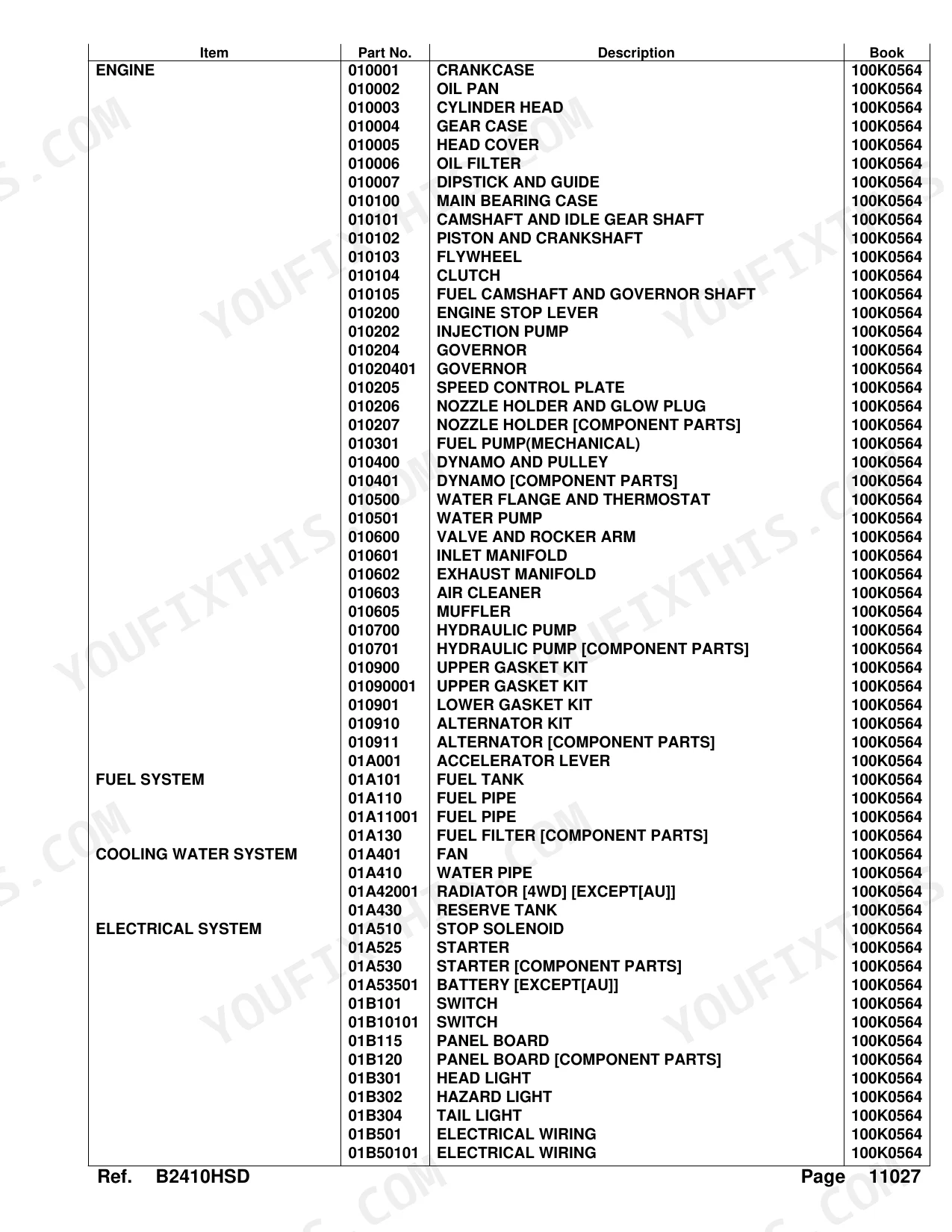


The B2410HSD 4WD HST tractor breaks down into 334 pages here, every system documented: engine internals, fuel and cooling, drivetrain, hydraulics, front axle, steering, and body panels. The catalog carries 167 pages of parts lists, each backed by an exploded-view diagram, running from crankcase and cylinder head through the HST unit, differential gear cases, and hydraulic control valve. Electrical listings spell out fuse ratings from 5A to 30A, and the crankcase assembly is cataloged at 32 kgf, the kind of detail that marks factory-sourced data rather than an aftermarket reprint. Order the wrong part and you eat a second freight charge plus another week of downtime. Everything is bookmarked by section and keyword-searchable, so you can open it on a tablet at the machine and pull your REF number before reaching for the phone.
What's Inside This Kubota B2410HSD Parts Manual
| System | Pages |
|---|---|
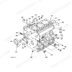
| Crankcase | 6-8 |
| Oil Pan | 9-10 |
| Cylinder Head | 11-12 |
| Gear Case | 13-15 |
| Head Cover | 16-17 |
| Oil Filter | 18-19 |
| Dipstick and Guide | 20-21 |
| Main Bearing Case | 22-24 |
| Camshaft and Idle Gear Shaft | 25-26 |
| Piston and Crankshaft | 27-28 |
| Flywheel | 29-30 |
| Clutch | 31-32 |
| Fuel Camshaft and Governor Shaft | 33-34 |
| Engine Stop Lever | 35-37 |
| Injection Pump | 38-39 |
| Governor | 40-43 |
| Speed Control Plate | 44-45 |
| Nozzle Holder and Glow Plug | 46-47 |
| Nozzle Holder [Component Parts] | 48-49 |
| Fuel Pump (Mechanical) | 50-51 |
| Dynamo and Pulley | 52-54 |
| Dynamo [Component Parts] | 55-56 |
| Water Flange and Thermostat | 57-58 |
| Water Pump | 59-60 |
| Valve and Rocker Arm | 61-62 |
| Inlet Manifold | 63-64 |
| Exhaust Manifold | 65-66 |
| Air Cleaner | 67-68 |
| Muffler | 69-71 |
| Hydraulic Pump | 72-73 |
| Hydraulic Pump [Component Parts] | 74-75 |
| Upper Gasket Kit | 76-79 |
| Lower Gasket Kit | 80-81 |
| Alternator Kit | 82-83 |
| Alternator [Component Parts] | 84-85 |
| Accelerator Lever | 86-87 |
| Fuel Tank | 88-90 |
| Fuel Pipe | 91-94 |
| Fuel Filter [Component Parts] | 95-96 |
| Fan | 97-98 |
| Water Pipe | 99-100 |
| Radiator [4WD] [Except[AU]] | 101-103 |
| Reserve Tank | 104-105 |
| Stop Solenoid | 106-108 |
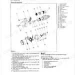
| Starter | 109-110 |
| Starter [Component Parts] | 111-113 |
| Battery [Except[AU]] | 114-115 |
| Switch | 116-119 |
| Panel Board | 120-121 |
| Panel Board [Component Parts] | 122-123 |
| Head Light | 124-125 |
| Hazard Light | 126-128 |
| Tail Light | 129-130 |
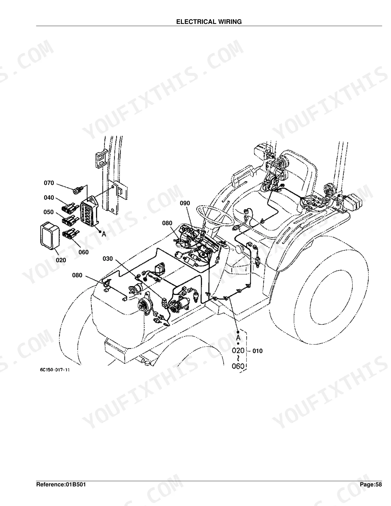
| Electrical Wiring | 131-135 |
| Clutch Rod | 136-137 |
| Clutch Pedal | 138-139 |
| Clutch Housing [4WD] | 140-141 |
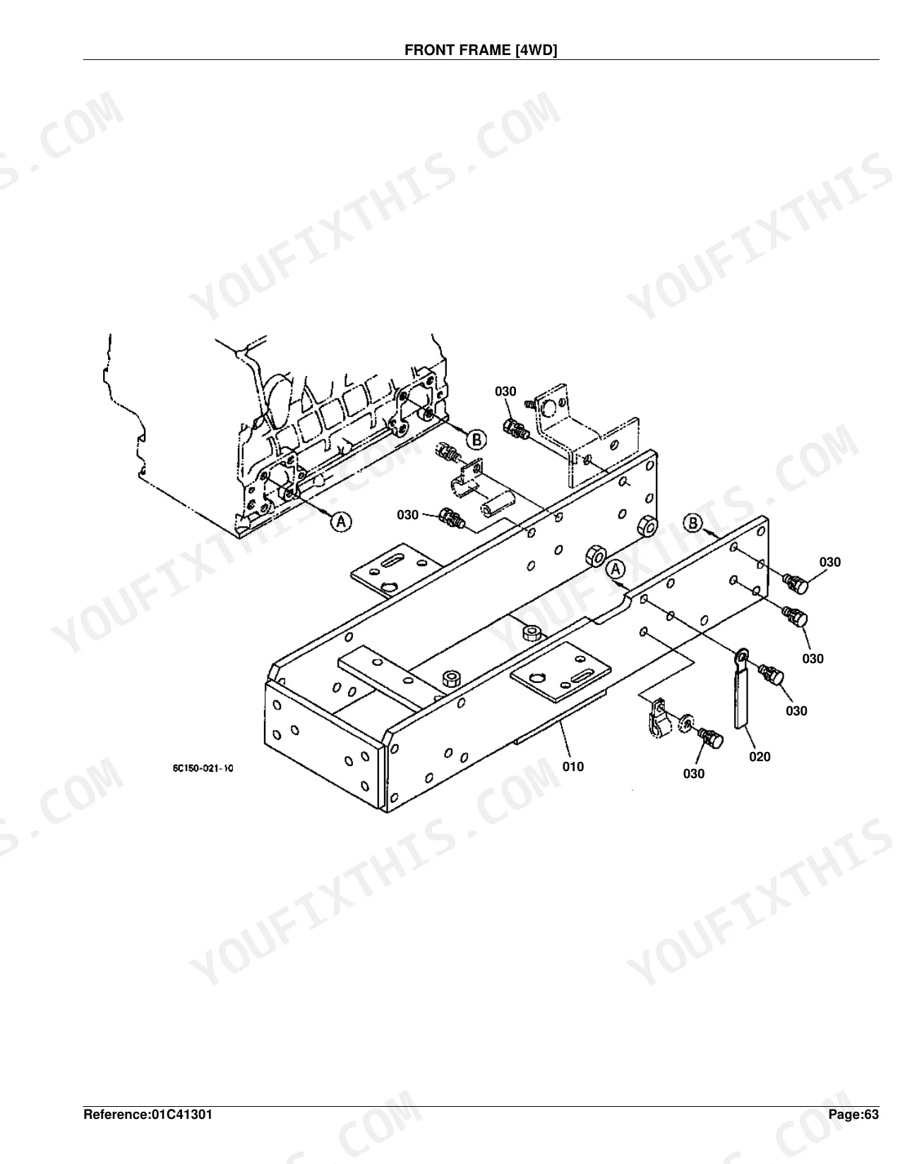
| Front Frame [4WD] | 142-143 |
| Center Frame | 144-145 |
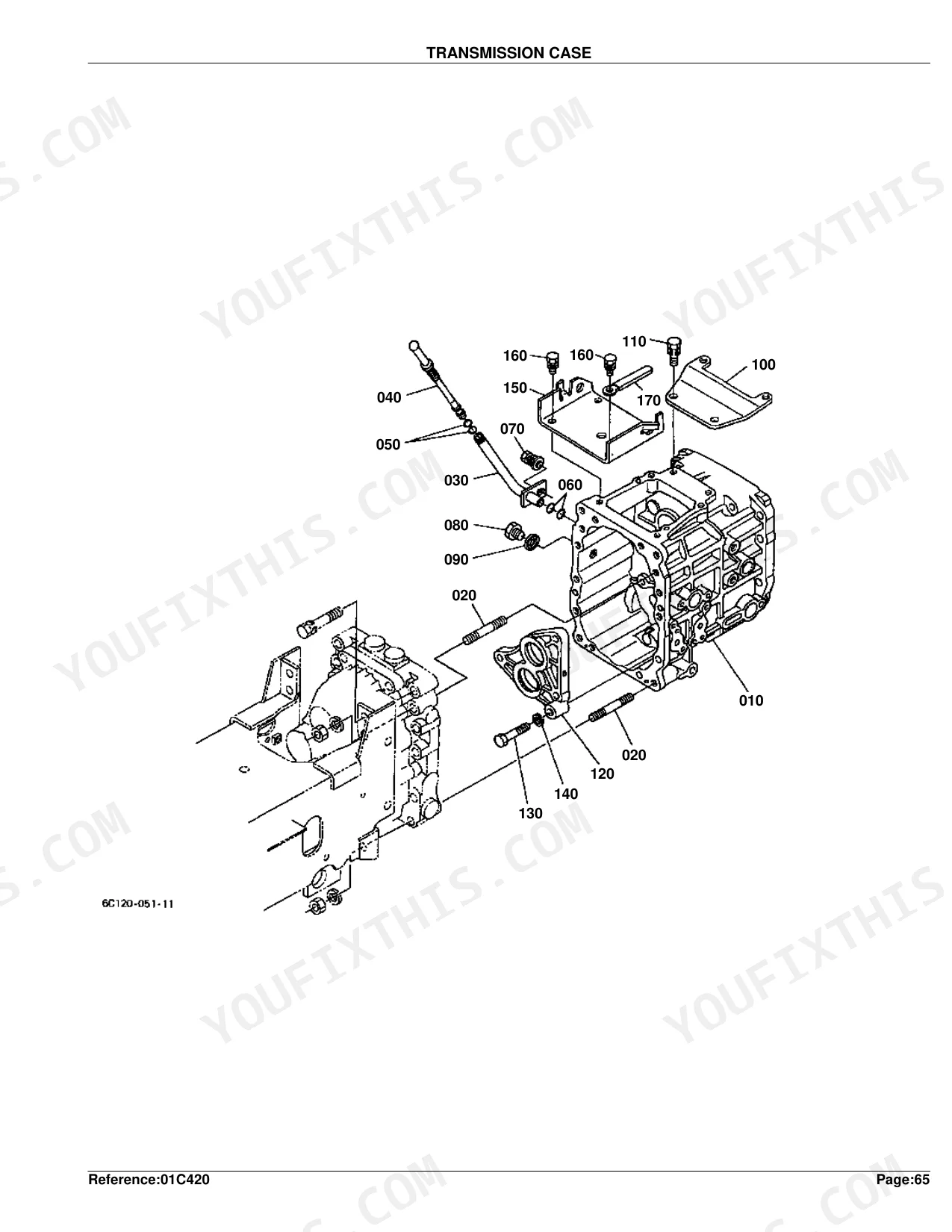
| Transmission Case | 146-148 |
| Differential Gear Case | 149-150 |
| Rear Axle Case [Except[Bi-Speed Turn Type]] | 151-152 |
| Clutch Shaft | 153-154 |
| Propeller Shaft | 155-156 |
| HST | 157-158 |
| HST [Component Parts] | 159-161 |
| Front Shaft | 162-163 |
| PTO Shaft | 164-165 |
| Mid PTO | 166-167 |
| Rear Differential | 168-169 |
| Front Wheel Propeller Shaft [4WD] | 170-171 |
| 2nd Shaft | 172-173 |
| 3rd Shaft | 174-175 |
| 4th Shaft | 176-177 |
| Range Gear Shift Fork | 178-179 |
| PTO Gear Shift Fork | 180-181 |
| Differential Lock Shift Fork | 182-183 |
| Rear Axle | 184-185 |
| Brake | 186-187 |
| Brake Rod 1 | 188-189 |
| Parking Brake Lever [Except[AU]] | 190-191 |
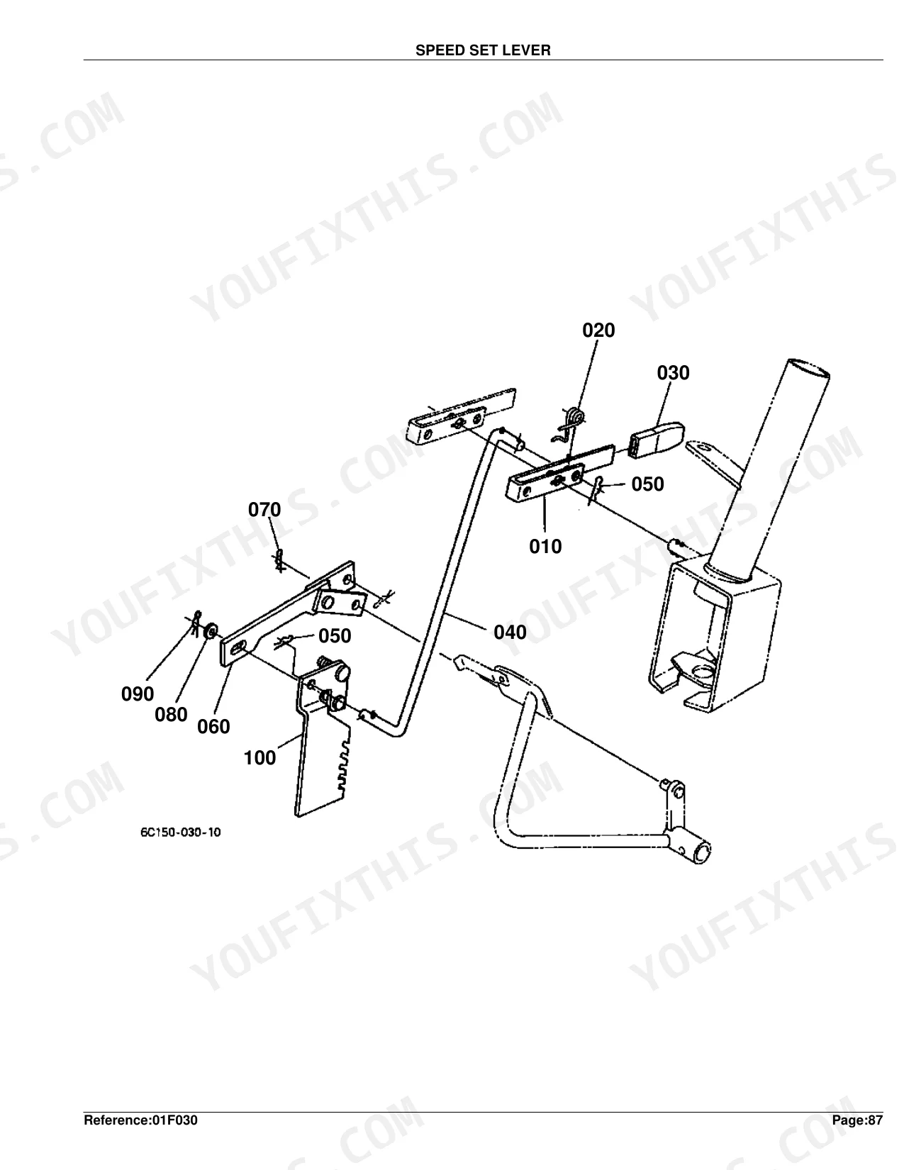
| Speed Set Lever | 192-193 |
| Neutral Holder Link | 194-195 |
| Speed Control Pedal | 196-197 |
| Range Gear Shift Lever | 198-199 |
| Front Wheel Drive Lever [4WD] | 200-201 |
| PTO Gear Shift Lever | 202-204 |
| Hydraulic Control Lever | 205-206 |
| Brake Pedal | 207-208 |
| Differential Lock Pedal | 209-210 |
| Front Axle Case [4WD] [Except[Bi-Speed Turn Type]] | 211-220 |
| Front Differential[4WD][Except[Bi-Speed Turn Type]] | 213-214 |
| Differential Gear Shaft [4WD] | 215-216 |
| Bevel Gear Case [4WD] | 217-218 |
| Front Axle [4WD] | 221-222 |
| Front Drive Shaft[4WD][Except[Bi-Speed Turn Type]] | 223-224 |
| Knuckle Arm [4WD] | 225-226 |
| Drag Link | 227-228 |
| Tie Rod [4WD] | 229-230 |
| Steering Handle | 231-232 |
| Steering Post | 233-234 |
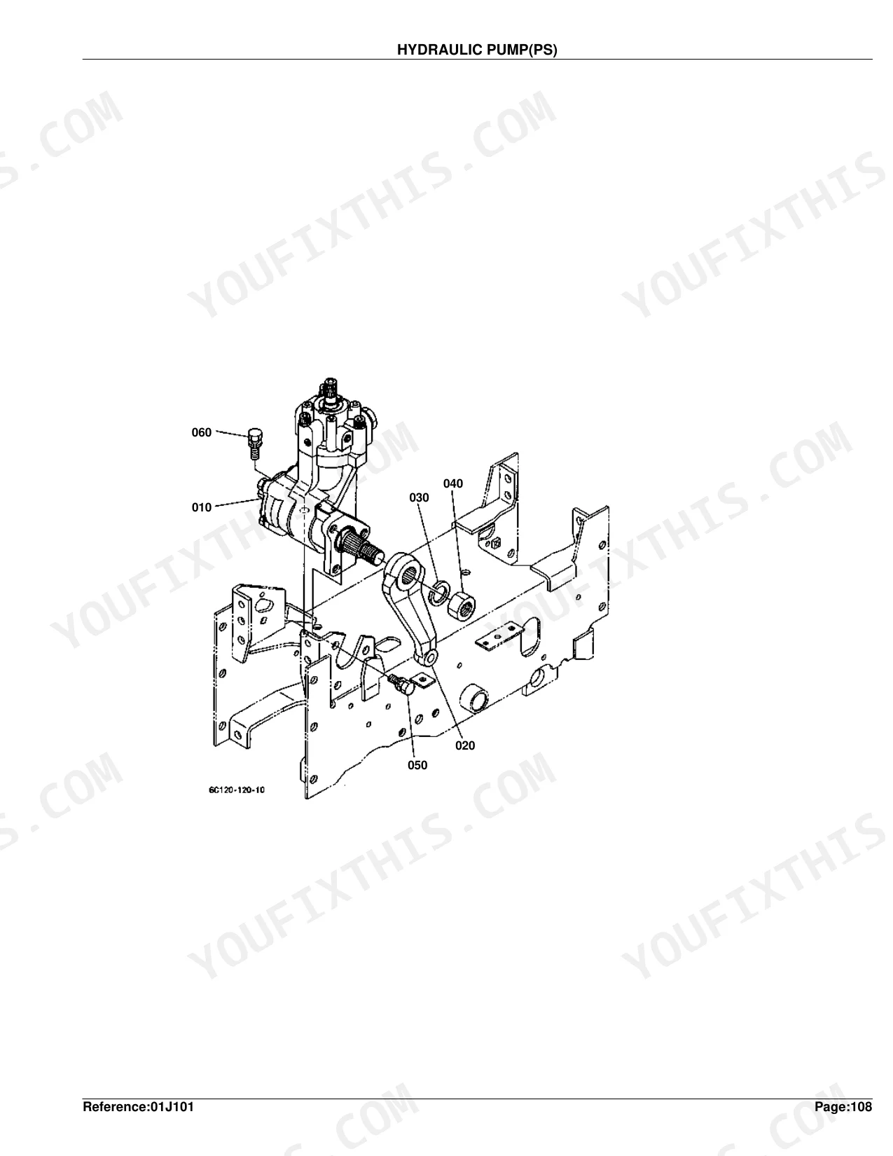
| Hydraulic Pump (PS) | 235-236 |
| Hydraulic Pump (PS) [Component Parts] | 237-238 |
| Hydraulic Oil Line (Suction) | 239-241 |
| Hydraulic Oil Line (Delivery) | 242-243 |
| Hydraulic Oil Line (Steering) | 244-246 |
| Hydraulic Oil Line (HST) | 247-248 |
| Hydraulic Oil Line (Oil Cooler) | 249-251 |
| Hydraulic Oil Line (F/M) | 252-253 |
| Hydraulic Cylinder | 254-256 |
| Hydraulic Piston/Lift Arm | 257-258 |
| Feed Back Lever | 259-260 |
| Control Valve | 261-262 |
| Control Valve [Component Parts] | 263-264 |
| 3-Point Linkage 2 (Lift Rod) | 265-266 |
| Lower Link | 267-268 |
| 3-Point Linkage 1 (Lower Link) | 269-270 |
| Check Chain | 271-272 |
| Drawbar | 273-274 |
| Hitch | 275-276 |
| PTO Protector [Except[AU]] | 277-278 |
| Front Grille [Except[AU]] | 279-280 |
| Bonnet | 281-282 |
| Panel Cover | 283-284 |
| Side Cover [Except[AU]] | 285-286 |
| Shutter Plate | 287-289 |
| Fender [Except[Bi-Speed Turn Type]] | 290-291 |
| Fender Stay [Except[Bi-Speed Turn Type]] | 292-293 |
| Floor Seat | 294-295 |
| Seat Support | 296-298 |
| Step | 299-300 |
| ROPS Kit (Rigid Type) | 301-302 |
| Smv Emblem | 303-304 |
| Front Wheel (7-12) [Except[AU]] | 305-306 |
| Front Wheel (21X8.00-10) [Except[AU]] | 307-308 |
| Front Wheel (23X8.50-12) [Except[AU]] | 309-312 |
| Rear Wheel (11.2-16) [Except[AU]] | 313-314 |
| Rear Wheel (31X15.5-15) [Except[AU]] | 315-316 |
| Rear Wheel (33X12.5-15) [Except[AU]] | 317-318 |
| Rear Wheel (12-16.5) [Except[AU]] | 319-320 |
| Label [4WD] [Except[Bi-Speed Turn Type]] [A] | 321-323 |
| Label [4WD] [Except[Bi-Speed Turn Type]] [CA] | 324-326 |
| Accessories and Service Parts | 327-328 |
| Working Light Kit [Option] | 329-330 |
| Power Steering Hose Kit [Option] | 331-332 |
| ROPS Kit (Foldable Type) [Option] | 333-334 |
Quick Reference Specifications
| Specification | Value | Page |
|---|---|---|
| FUSE current rating | 30A | p. 133 |
| FUSE AUTO current rating | 5A | p. 133 |
| SOLENOID STOP weight | 0.27 kgf | p. 108 |
| ASSY SOLENOID STOP weight | 0.28 kgf | p. 108 |
| CRANKCASE (COMP.CRANKCASE) Weight | 32 kgf | p. 8 |
| OIL PAN (COMP.OIL PAN) Weight | 1.2 kgf | p. 10 |
| CYLINDER HEAD (COMP.CYLINDER HEAD) Weight | 9.2 kgf | p. 12 |
| GEAR CASE (ASSY CASE GEAR) Weight | 3.46 kgf | p. 15 |
| HEAD COVER (ASSY COVER CYL.HEAD) Weight | 0.78 kgf | p. 17 |
| OIL FILTER (ASSY CARTRIDGE OIL) Weight | 0.35 kgf | p. 19 |
| PISTON AND CRANKSHAFT (COMP.CRANKSHAFT) Weight | 9.58 kgf | p. 28 |
| FLYWHEEL (COMP.FLYWHEEL) Weight | 17.2 kgf | p. 30 |
Kubota B2410HSD Common Problems This Manual Covers
Kubota B2410HSD cranks but will not start due to a suspected bad fuel shutoff solenoid p. 106
Pull up the stop solenoid exploded view on page 106. The right replacement assembly matches the 0.27 kgf weight given on page 108. Cross-reference the solenoid and mounting hardware part numbers against your tractor serial number before you order.
Manual Section: Stop SolenoidEntire electrical system is dead or intermittent and need replacement fuse part numbers p. 131
Trace the electrical wiring components on page 131 for exact fuse part numbers, including the main 30A fuse and the smaller auto fuses. Match them to the fuse block layout in the parts list so you order the right relays and terminals.
Manual Section: Electrical WiringExhaust is excessively loud or blowing black smoke near the engine side panels p. 69
Inspect the muffler exploded view on page 69 and read off the part number for the main exhaust assembly, which should match the 2.62 kgf weight on page 71. Add the mounting gaskets and hardware shown in the diagram for a clean seal.
Manual Section: MufflerFrequently Asked Questions
What are the replacement specifications for fuses?
Several fuses are listed with amperage ratings. In the ELECTRICAL WIRING section, part 1G111-65720 is 30A, 66426-80010 is 5A, 48100-55880 is 10A, 36919-56650 is 20A, and 52300-41630 is 10A.
What are the replacement specifications for relays?
A 'COMP.RELAY' appears under part number 68881-53540 in the ALTERNATOR KIT and SWITCH sections. No electrical values such as voltage or amperage are given for it, just the part number.
How will I receive this Kubota B2410HSD Parts Catalog?
This is a 334-page searchable PDF ready for immediate download. It works on any device, so you can pull it up on your phone while under the hood. No shipping, no waiting.
Are there any print restrictions on this Kubota B2410HSD manual?
None at all. The PDF is DRM-free, so print whatever sections you want to take out to the shop. Standard letter or A4 paper works.
Does this Kubota B2410HSD manual include hydraulic schematics?
This is a parts catalog, so it shows exploded parts diagrams rather than circuit schematics. It includes detailed exploded views of the hydraulic components — pump, control valve, cylinder, and oil lines — with OEM part numbers, not wiring-style circuit diagrams.
Document Quality
This document is a scanned PDF with an OCR text layer, allowing you to search and copy all text. The text is generally crisp and easy to read throughout the document. Diagrams and illustrations are raster images, but they are clear, and all labels are readable. Pages are clean with no noticeable scan artifacts, stains, or skewed content. There are no entirely blank pages, though some diagram pages provide zoomed-in views of specific parts.


Reviews
There are no reviews yet.