


Need the official setup guide for your Kubota B2650 or B2660 Snowblower? This 50-page operator manual (OEM #251551) walks through Kubota's installation, operation, and maintenance procedures from sub-frame to first snow run. Five pages of safety information cover pre-operation and during-operation warnings. Seven pages of sub-frame installation detail hydraulic connections for 3-point systems, front loaders, and the B2056 valve kit. Operating controls for chute rotation, lift, and snowblower drive sit alongside daily maintenance steps for skid shoes, drive chain, and chute deflector adjustment. A torque chart lists SAE Grade 5 and Metric Grade 8.8 values: set the M12-1.25 x 45 front axle housing bolts to 91-108 ft. lbs. (123.5-147.0 N•m) and keep drive chain deflection between 1/8 and 3/16 of an inch. No more guessing at mounting specs that should have shipped in the box. Bookmarked throughout, so any spec is a keyword search away.
What's Inside This Kubota B2650, B2660 Operator Manual
| System | Pages | Key Topics |
|---|---|---|
| Safety Signs | 5-6 | Safety Sign Locations, Care Of Safety Signs, Sign Illustrations & Part Numbers |
| Specifications | 7-7 | Authorized Tractor Applications |
| Tractor Preparation | 9-10 | Steering Stop Plate Installation |
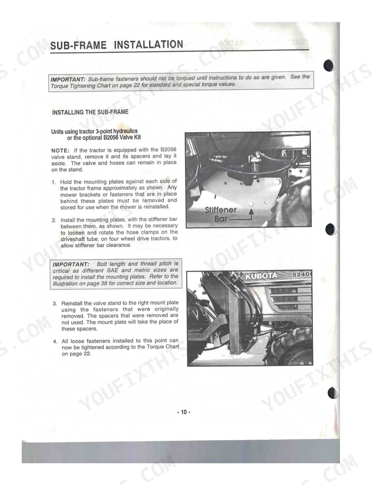
| Sub-Frame Installation | 11-16 | Installing The Sub-Frame, Units Using 3-Point Hydraulics Or The B2056 Valve Kit, Units With Front Loader, All Unit Combinations, Installing Handle Support, Hydraulic Connections |
| Hydraulic Adjustments | 17-17 | 3-Point Hydraulic Control Valve Return Spring (Lever Is Moved Too Far Forward, Hydraulic Relief Remains Partially Activated) |
| Additional Assembly Information | 18-18 | Important Notes, Pre-Delivery Inspection, Hydraulic Control Valve Return Spring Adjustments, Drive Shield Exchange |
| Snowblower Installation | 19-22 | Fastening To The Lift Frame, Installing The Chute, Installing The Chute Handle, Connecting The Driveshafts, Skid Shoe Adjustment |
| Torque Tightening Chart | 23-23 | Standard Torque Application Chart (SAE Grade 5, Metric Grade 8.8), Special Torque Applications (B2400 Tractor Front Axle Housing, Sub-Frame Fasteners) |
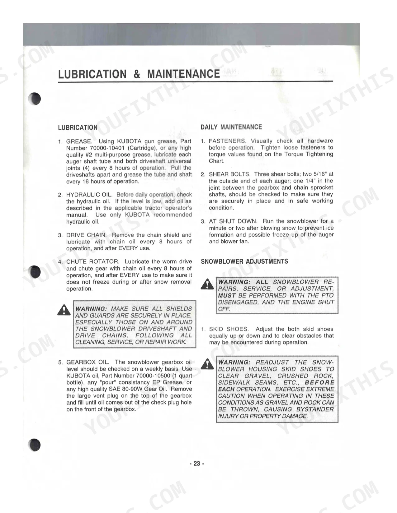
| Lubrication & Maintenance | 24-25 | Lubrication, Daily Maintenance, Snowblower Adjustments (Skid Shoes, Drive Chain, Chute Deflector) |
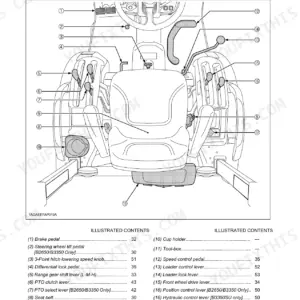
| Operating Instructions | 26-29 | Operating Controls (Chute Rotation, Lifting & Lowering, Snowblower Drive), Preparing For Snow Removal, Removing Snow, Transporting The Snowblower |
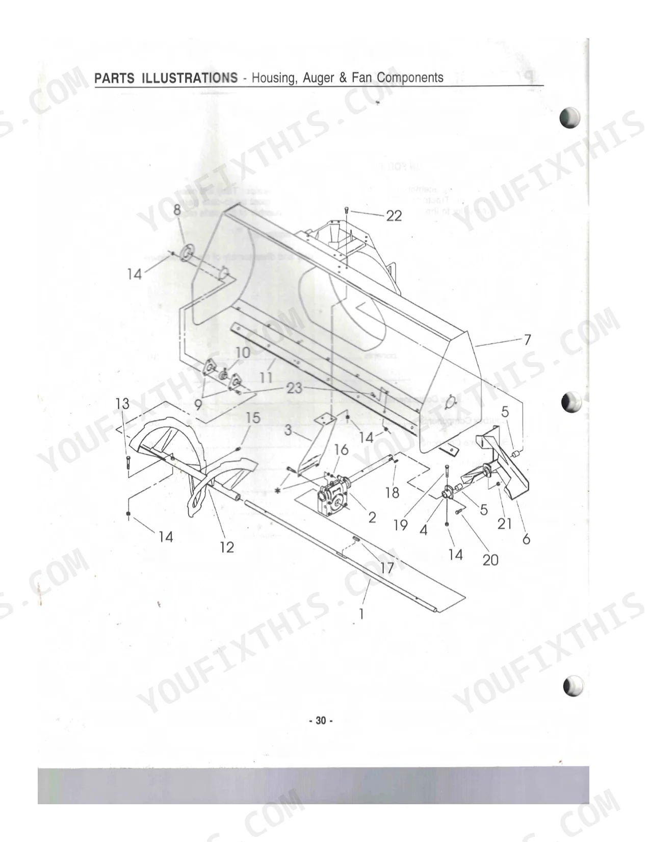
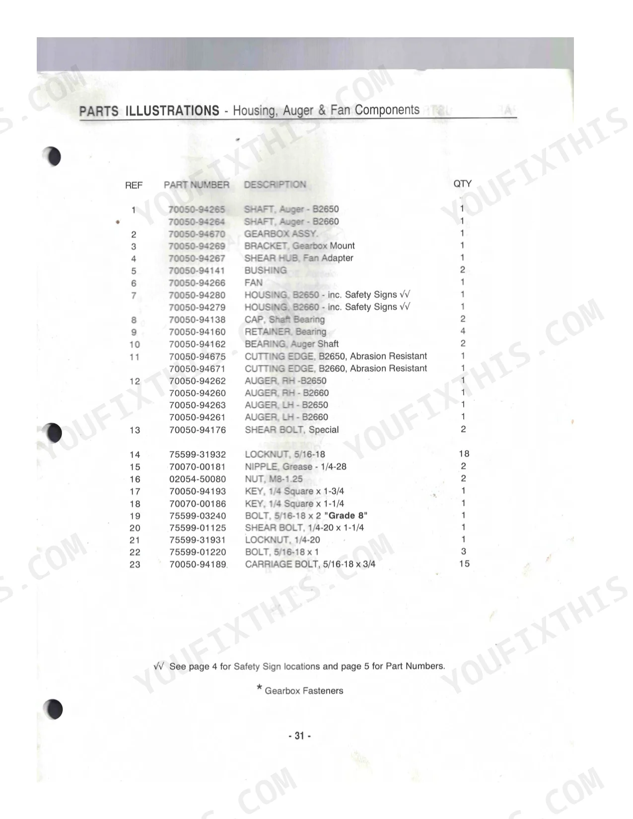
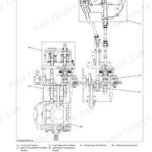
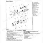
| Parts Illustrations | 30-46 | Housing, Auger & Fan Components, Drive Components, Discharge Chute Components, Gearbox Components, Sub-Frame Components, Hydraulic Lift Components, Driveshaft Components |
Quick Reference Specifications
| Specification | Value | Page |
|---|---|---|
| Front Axle Housing Bolt Torque (M12-1.25 x 45) | 91-108 ft. lbs. (123.5-147.0 N•m) | p. 9 |
| Front Axle Housing Nut Torque (M12-1.25) | 62-75 ft. lbs. (84.0-101.8 N•m) | p. 9 |
| Auger Shear Bolt Replacement Part Number | 70050-94176 | p. 32 |
| Fan Adapter Shear Bolt Replacement Part Number | 75599-01125 | p. 32 |
| Drive Chain Deflection | 1/8 to 3/16 of an inch | p. 25 |
| Drive Chain Replacement Part Number | 70050-94276 | p. 34 |
| Gearbox Pin (M8 x 35) Replacement Part Number | 70050-94223 | p. 38 |
| Gearbox Pin (M6 x 12) Replacement Part Number | 70050-94224 | p. 38 |
| Hydraulic Hose (1/4 x 28) Replacement Part Number | 70050-94515 | p. 42 |
| Quick Disconnect Coupler Replacement Part Number | 75532-66323 | p. 42 |
| Hydraulic Lift Inconsistency Adjustment Procedure | Adjust 3-point hydraulic control valve return spring by filing collar (if lever moves too far forward) or adding shims (if relief remains partially activated) to ensure snowblower remains in transport position without downward drift and relief circuit fully deactivates. | p. 17 |
| Overall Length | 132.2" (3558 mm) | p. 7 |
Kubota B2650, B2660 Common Problems This Manual Covers
Kubota B2650 front snowblower won't raise or holds position only when engine is at idle p. 17
Check hydraulic oil level on page 24 before anything else. Then inspect the 3-point control valve return spring per page 17; if the lift lever drifts past the raise detent, file the spring collar. If hydraulic relief stays partially activated, add shims behind the spring. Verify the blower raises freely at rated PTO of 903 RPM.
Manual Section: Hydraulic AdjustmentsHydraulic up/down lift or chute rotation acts erratic or reversed right after connecting p. 11
Disconnect all quick-disconnect couplers and reseat until each clicks fully locked. Trace both hydraulic hoses back to their ports per pages 15-16; a swapped supply and return line reverses lift direction. Confirm the chute rotation hose sweeps the full 200-degree arc without kinking, then test all functions at low engine speed.
Manual Section: Sub-Frame InstallationAuger suddenly stops turning mid-run and snowblower loses all drive after striking packed snow or debris p. 24
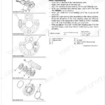
Disengage PTO immediately and clear the intake before inspecting shear bolts per page 24. A broken shear bolt is the first thing to rule out; replace auger bolts with part 70050-94176 or fan adapter bolts with 75599-01125 on page 32. Grease auger shaft and driveshaft universal joints every 8 hours per page 24. Never substitute a standard bolt.
Manual Section: Lubrication & MaintenanceMounting hardware and attachment bolts work loose with vibration after the first few hours p. 24
Walk the full attachment before each session and tighten any loose hardware per the fastener check on page 24. Sub-frame bolts (1/2-13) torque back to 60 ft. lbs. (81.6 N•m) per page 23. Hardware loosens fastest in the first few hours after installation; make checking fasteners part of every pre-operation walkaround.
Manual Section: Lubrication & MaintenanceDrive chain makes noise, feels loose, or skips under load during snowblower operation p. 25
Open the drive cover and press the chain midpoint by hand. Deflection should be 1/8 to 3/16 of an inch per page 25; more than that means the chain adjuster needs to move. Lubricate the chain every 8 hours per page 24. A dry or over-slack chain wears sprocket teeth quickly and shortens component life.
Manual Section: Lubrication & MaintenanceFrequently Asked Questions
What are the replacement specifications for shear pins?
The manual specifies three shear bolts: two 5/16" at the outside end of each auger and one 1/4" in the joint between the gearbox and chain sprocket shafts. For replacement, use Part Number 70050-94176 for the 'SHEAR BOLT, Special' (QTY 2) and Part Number 75599-01125 for the 'SHEAR BOLT, 1/4-20 x 1-1/4' (QTY 1).
What are the replacement specifications for drive chain?
The drive chain for the snowblower is specified as a '#40 Series - Special' with Part Number 70050-94276. If needed, a 'HALF LINK' (Part Number 70050-94556) and a 'CONNECTING LINK' (Part Number 70050-94283) are also available.
What do I get after purchasing this Kubota B2650, B2660 manual?
A 50-page Operator Manual in searchable PDF format, available the moment you complete checkout. View on computer, tablet, or phone (no shipping wait).
Can I print specific sections of this Kubota B2650, B2660 Operator Manual?
Absolutely. No DRM or copy protection. Print the whole manual or just the pages you need. Any home or office printer works.
Document Quality
This document is a scanned copy of a physical manual, evident from the worn appearance and handwritten notes on the cover page. It includes an OCR layer, allowing you to search and copy text throughout the document. While the OCR text is clear, the underlying scanned text can appear slightly faded or blurry in some sections. Diagrams and illustrations are raster images, not vector, but their labels are generally readable. The pages exhibit typical scanning artifacts, including some smudges, stains, and slight skewing, and page 29 is largely blank.
Reviews
There are no reviews yet.