
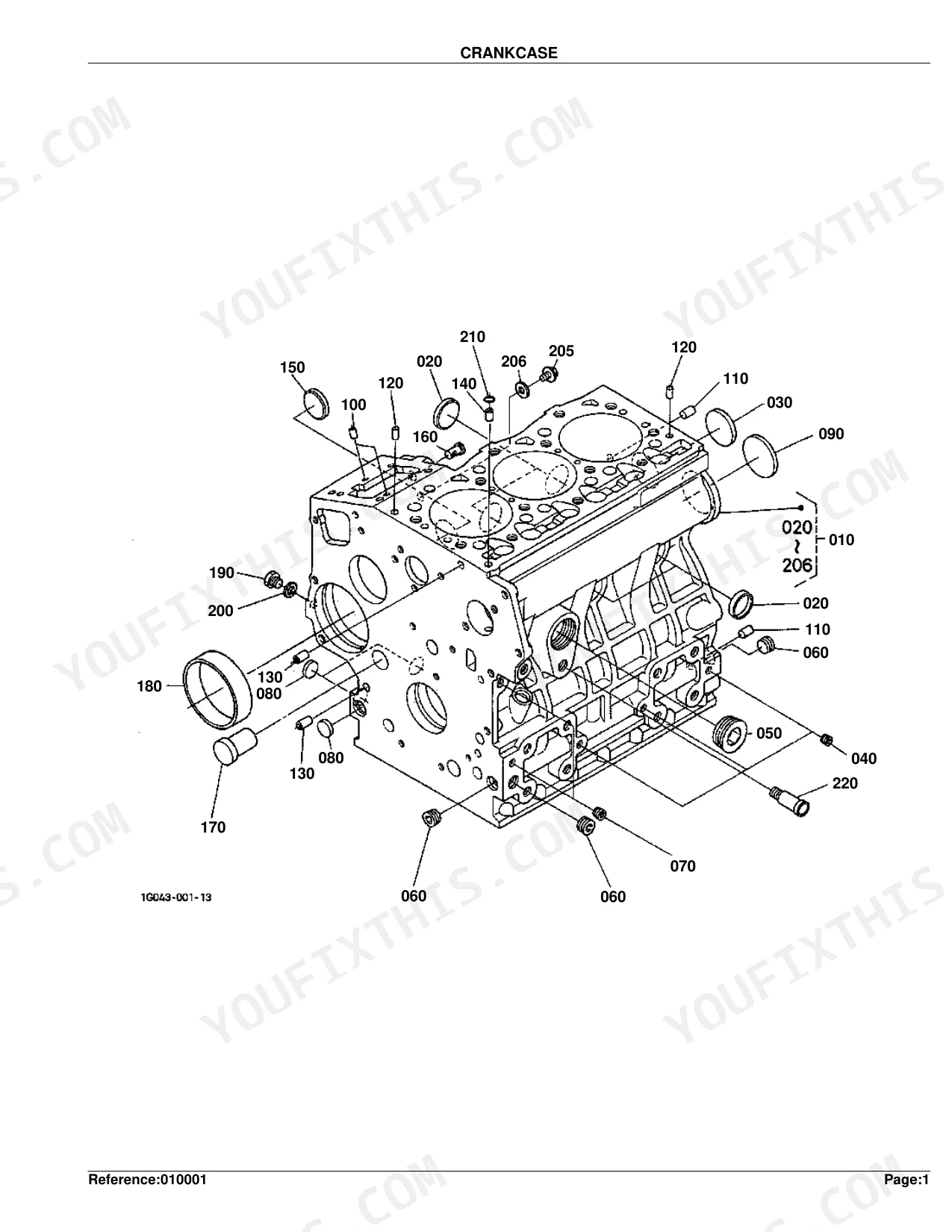
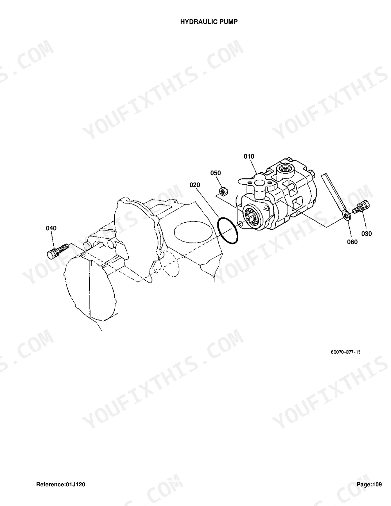
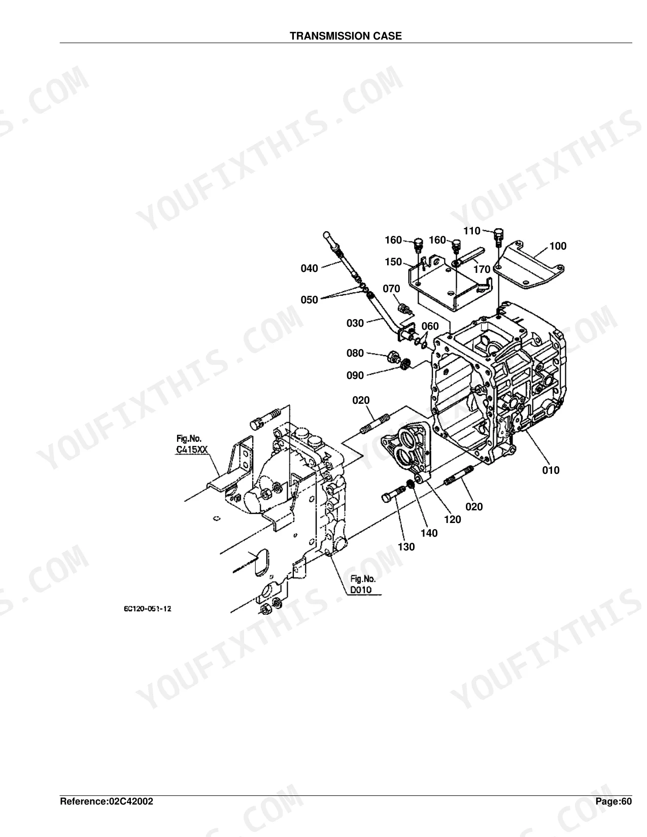
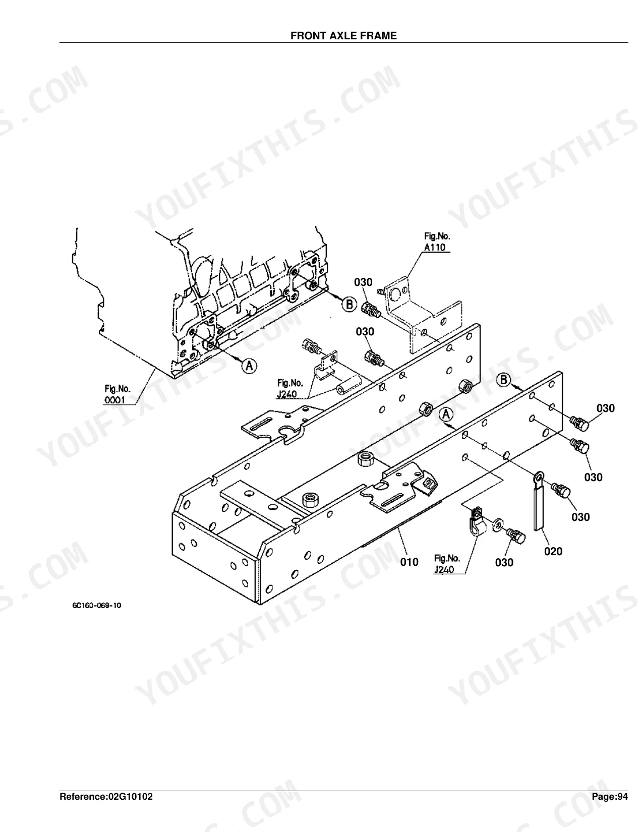
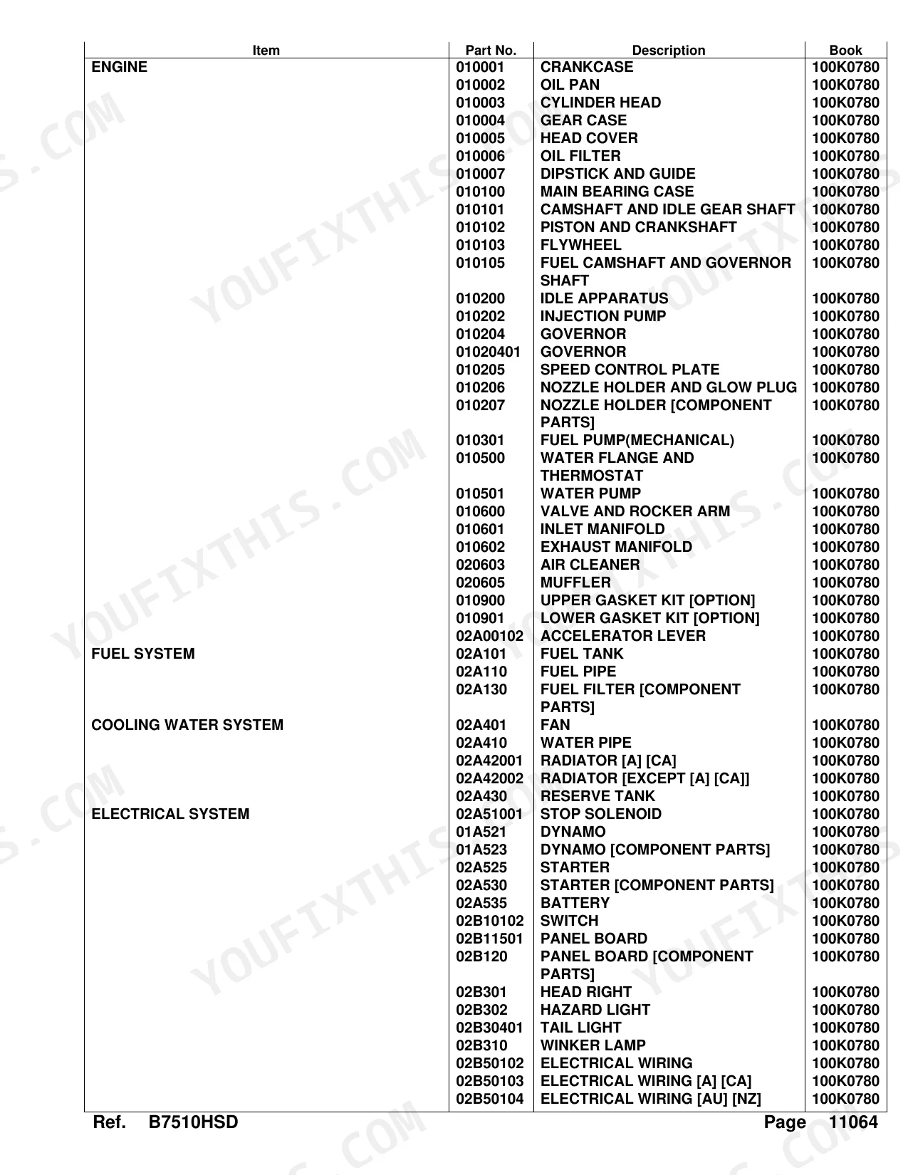
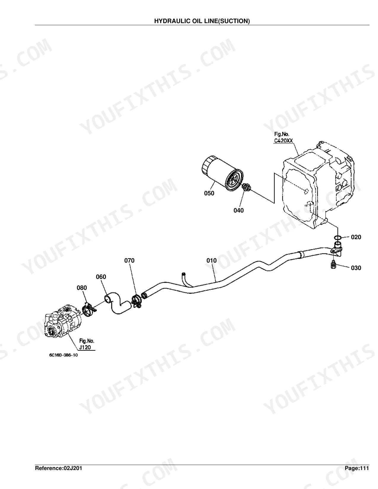
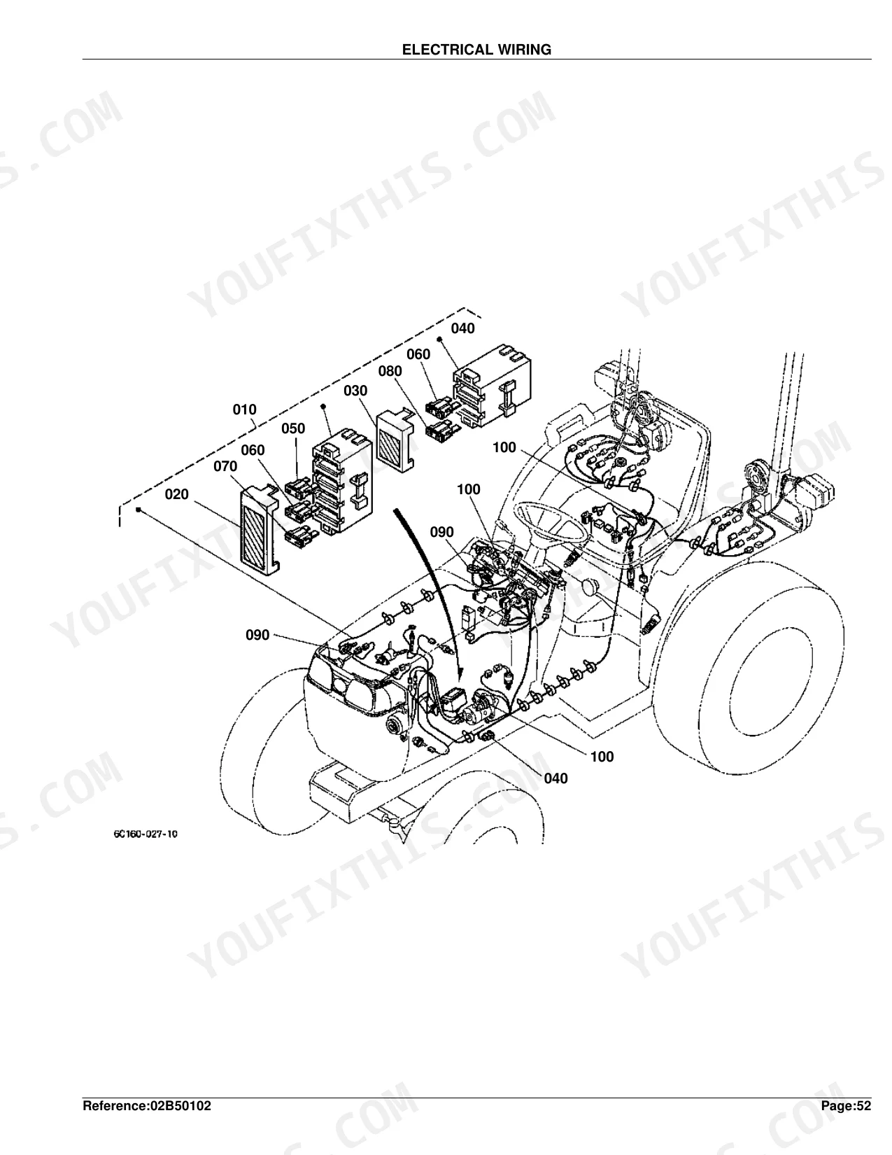
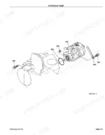
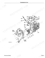
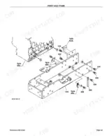
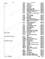
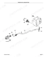
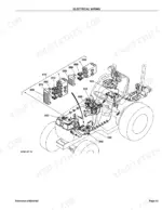
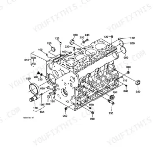
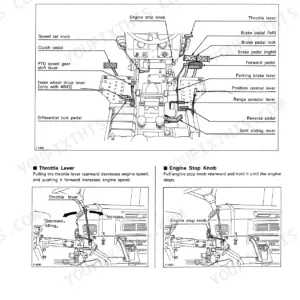
Matching a factory part number before you call the dealer is the whole point of this Kubota B7510HSD Parts Catalog (OEM #100K0780). Its 348 pages break down into 169 pages of master parts lists, 55 pages of engine component diagrams running from crankcase to injection pump and governor, and 22 pages of drivetrain exploded views across the HST, transmission case, clutch shaft, and PTO. Wiring diagrams cover three regional variants (North America, Australia, New Zealand), with front and rear wheel configurations for six tire sizes. The fuse chart confirms a 30A main fuse and auto fuses at 5A, 10A, 20A, and 30A. Match any reference number against a clean diagram instead of a worn paper list. Everything is bookmarked by system and searchable by keyword, so you can pull a part number on any device right at the machine.
What's Inside This Kubota B7510HSD Parts Manual
| System | Pages |
|---|---|
| Crankcase | 7-8 |
| Oil Pan | 9-10 |
| Cylinder Head | 11-12 |
| Head Cover | 15-16 |
| Oil Filter | 17-18 |
| Dipstick and Guide | 19-20 |
| Main Bearing Case | 21-22 |
| Camshaft and Idle Gear Shaft | 23-24 |
| Piston and Crankshaft | 25-26 |
| Flywheel | 27-28 |
| Fuel Camshaft and Governor Shaft | 29-30 |
| Idle Apparatus | 31-33 |
| Injection Pump | 34-35 |
| Governor | 36-39 |
| Speed Control Plate | 40-41 |
| Nozzle Holder and Glow Plug | 42-43 |
| Nozzle Holder [Component Parts] | 44-45 |
| Fuel Pump (Mechanical) | 46-47 |
| Water Flange and Thermostat | 48-49 |
| Water Pump | 50-51 |
| Valve and Rocker Arm | 52-53 |
| Inlet Manifold | 54-55 |
| Exhaust Manifold | 56-57 |
| Air Cleaner | 58-59 |
| Muffler | 60-61 |
| Upper Gasket Kit [Option] | 62-63 |
| Lower Gasket Kit [Option] | 64-65 |
| Accelerator Lever | 66-67 |
| Fuel Tank | 68-69 |
| Fuel Pipe | 70-71 |
| Fuel Filter [Component Parts] | 72-73 |
| Fan | 74-75 |
| Water Pipe | 76-77 |
| Radiator [A] [CA] | 78-79 |
| Radiator [Except [A] [CA]] | 80-81 |
| Reserve Tank | 82-83 |
| Stop Solenoid | 84-86 |
| Dynamo | 87-88 |
| Dynamo [Component Parts] | 89-90 |
| Starter | 91-92 |
| Starter [Component Parts] | 93-95 |
| Battery | 96-97 |
| Switch | 98-99 |
| Panel Board | 100-101 |
| Panel Board [Component Parts] | 102-103 |
| Head Right | 104-105 |
| Hazard Light | 106-107 |
| Tail Light | 108-109 |
| Winker Lamp | 110-111 |
| Electrical Wiring | 112-113 |
| Electrical Wiring [A] [CA] | 114-115 |
| Electrical Wiring [AU] [NZ] | 116-117 |
| Clutch | 118-119 |
| Clutch Rod | 120-121 |
| Clutch Pedal | 122-123 |
| Clutch Housing | 124-125 |
| Transmission Case | 128-129 |
| Rear Axle Case | 132-133 |
| Clutch Shaft | 134-135 |
| HST [Component Parts] | 140-145 |
| Range Gear Shift Fork | 162-163 |
| PTO Gear Shift Fork | 164-165 |
| Differential Lock Shift Fork | 166-167 |
| Rear Axle | 168-169 |
| Brake | 170-171 |
| Brake Rod | 172-173 |
| Parking Brake Lever [Except [AU] [NZ]] | 174-175 |
| Parking Brake Lever [AU] [NZ] | 176-177 |
| Speed Set Lever | 178-179 |
| Neutral Holder Link | 180-181 |
| Speed Control Pedal | 182-183 |
| Range Gear Shift Lever | 184-185 |
| Front Wheel Drive Lever | 186-187 |
| PTO Gear Shift Lever | 188-189 |
| Hydraulic Control Lever | 190-191 |
| Brake Pedal | 192-193 |
| Front Axle Frame | 196-197 |
| Front Axle Case | 198-207 |
| Front Axle | 208-209 |
| Steering Handle | 218-219 |
| Steering Post | 220-221 |
| Hydraulic Pump (PS) | 222-223 |
| Hydraulic Pump (PS) [Component Parts] | 224-225 |
| Hydraulic Oil Line (Suction) | 230-231 |
| Hydraulic Oil Line (Delivery) | 232-233 |
| Hydraulic Oil Line (Steering) | 234-235 |
| Hydraulic Oil Line (HST) | 236-237 |
| Hydraulic Oil Line (Oil Cooler) | 238-239 |
| Hydraulic Oil Line (F/M) | 240-241 |
| Hydraulic Cylinder | 242-243 |
| Hydraulic Piston/Lift Arm | 244-245 |
| Feed Back Lever | 246-247 |
| Control Valve | 248-249 |
| Control Valve [Component Parts] | 250-251 |
| 3-Point Linkage 2 (Lift Rod) | 252-253 |
| Lower Link | 254-255 |
| 3-Point Linkage 1 (Top Link) | 256-257 |
| Check Chain | 258-259 |
| Drawbar | 260-261 |
| Rear Hitch | 262-263 |
| PTO Protector [A] [CA] | 264-265 |
| PTO Protector [AU] [NZ] | 266-267 |
| Front Grille [A] [CA] | 268-270 |
| Bonnet | 273-274 |
| Rops (Rigid Type) [Except [AU]] | 297-298 |
| Rops (Foldable Type) | 299-300 |
| Front Wheel (6-12) [A] [CA] [B7510Dn [Option]] | 305-306 |
| Front Wheel (23*8.50-12) [A] [CA] | 307-312 |
| Front Wheel (21*8.00-10) [A] [CA] | 309-310 |
| Front Wheel (6-12) [Except [A] [CA]] | 313-314 |
| Front Wheel (22*8.50-12) [Except [A] [CA]] | 315-316 |
| Rear Wheel (9.5-16) [A] [CA] | 317-318 |
| Rear Wheel (33*12.5-15) [A] [CA] | 319-320 |
| Rear Wheel (31*15.5-15) [A] [CA] | 321-322 |
| Rear Wheel (12-16.5) [A] [CA] | 323-324 |
| Rear Wheel (9.5-16) [Except [A] [CA]] | 325-326 |
| Rear Wheel (31*13.5-15) [Except [A] [CA]] | 327-328 |
| Label [A] [CA] [English] | 329-330 |
| Label [A] [CA] [French] | 331-332 |
| Label [AU] | 333-334 |
| Label [NZ] | 335-336 |
| Accessories and Service Parts | 337-338 |
| Alternator Kit [Option] | 339-340 |
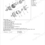
| Alternator [Component Parts] [Option] | 341-342 |
| Working Light Kit [Option] | 343-344 |
| Horn Kit [Option] [AU] [NZ] | 345-346 |
| Brake Lamp Kit [Option] [AU] [NZ] | 347-348 |
Quick Reference Specifications
| Specification | Value | Page |
|---|---|---|
| FUSE | 30A | p. 113 |
| FUSE AUTO | 5A | p. 113 |
| Engine Crankcase Weight | 32.5 kgf | p. 8 |
| Cylinder Head Weight | 8.72 kgf | p. 12 |
| Oil Filter Weight | 0.35 kgf | p. 18 |
| Piston Weight (STD) | 0.4 kgf | p. 26 |
| Flywheel Weight | 17.2 kgf | p. 28 |
| Injection Pump Weight | 1 kgf | p. 35 |
| Radiator Weight | 2.5 kgf | p. 79 |
| Starter Weight | 2.75 kgf | p. 92 |
| Battery Bracket Weight | 2.6 kgf | p. 97 |
| Clutch Disk Weight | 0.88 kgf | p. 119 |
Kubota B7510HSD Common Problems This Manual Covers
Kubota B7510HSD hydrostatic transmission has no forward or reverse drive, need HST internal component part numbers p. 140
Open the HST Component Parts exploded view on pages 140-145 to identify individual internal components and their part numbers. Check the Transmission Case diagram on page 128 to confirm drivetrain context. If the hydraulic pump (PS) is also involved, find it on page 222; the pump assembly weighs 11.1 kgf, so confirm your serial-range part number before ordering.
Manual Section: HST [Component Parts]Engine cranks slowly or won't crank at all, need starter assembly and solenoid component part numbers p. 91
Find the complete starter assembly part number in the Starter exploded view on page 91; the unit weighs 2.75 kgf. For internal components including brushes and the drive assembly, open Starter Component Parts on pages 93-95. If the fault is in the fuel shutdown circuit rather than the starter, cross-reference the Stop Solenoid parts on page 84.
Manual Section: StarterSafety switches or dashboard electrics fail intermittently, need correct fuse and switch part numbers to replace p. 112
Pull the Electrical Wiring diagram on page 112 to trace the affected circuit, then check page 113 for confirmed fuse ratings: 5A, 10A, 20A, and 30A variants are specified. Locate fuse and switch part numbers in the Switch exploded view on page 98. For safety interlock components, check the Panel Board Component Parts diagram on page 102.
Manual Section: Electrical WiringEngine overheating under load, need radiator assembly, fan, and coolant pipe replacement part numbers p. 78
Locate radiator part numbers on page 78 for North American and Canadian markets, or page 80 for all other markets. The radiator assembly weighs 2.5 kgf; confirm the correct regional variant before ordering. Find fan blade assembly parts on page 74 and coolant hose hardware on page 76. For the reserve tank and overflow components, check page 82.
Manual Section: Cooling System ComponentsTractor won't start after sitting, fuel delivery suspected, need fuel filter component and pipe part numbers p. 72
Start at the Fuel Filter Component Parts diagram on page 72 to identify individual filter sub-parts and their part numbers. Trace connecting fuel pipe hardware on page 70. For the fuel tank and cap assembly, check page 68. The injection pump shown on page 34 weighs 1 kgf; if the pump is also suspect, cross-reference its component list before ordering.
Manual Section: Fuel System ComponentsFrequently Asked Questions
What are the replacement specifications for hydraulic filter?
Two cartridge oil filters are listed. The hydraulic oil line (HST) uses part number 66021-36060 on page 237, and the hydraulic oil line (suction) uses 67955-37710 on page 231. This parts manual gives no replacement intervals or procedures.
What are the replacement specifications for fuel filter?
Page 73 lists the fuel filter component parts: the fuel filter assembly is 6A320-58862 and the filter itself is 6A320-59930. Replacement intervals and procedures are not covered in this parts manual.
Is this Kubota B7510HSD Parts Catalog a digital download?
Yes. The 348-page searchable PDF downloads right after checkout, ready to open on a laptop, tablet, or phone out in the shop.
Can I print this Kubota B7510HSD manual?
No restrictions at all. Print individual pages, full chapters, or the entire manual. The PDF is completely unlocked.
Does this Kubota B7510HSD manual include wiring diagrams?
Yes. You'll find full electrical schematics with wire routing diagrams, connector identification, and circuit descriptions.
Document Quality
This document is a scanned PDF with an OCR text layer, allowing you to search and copy text throughout. The text is crisp and clear, making it easy to read all part numbers and descriptions. Diagrams and illustrations are sharp and their labels are clearly readable, providing good visual references for the parts. Pages are generally clean with minimal scan artifacts, and there are no notable blank or filler pages, so you get content on every relevant sheet.


Reviews
There are no reviews yet.