
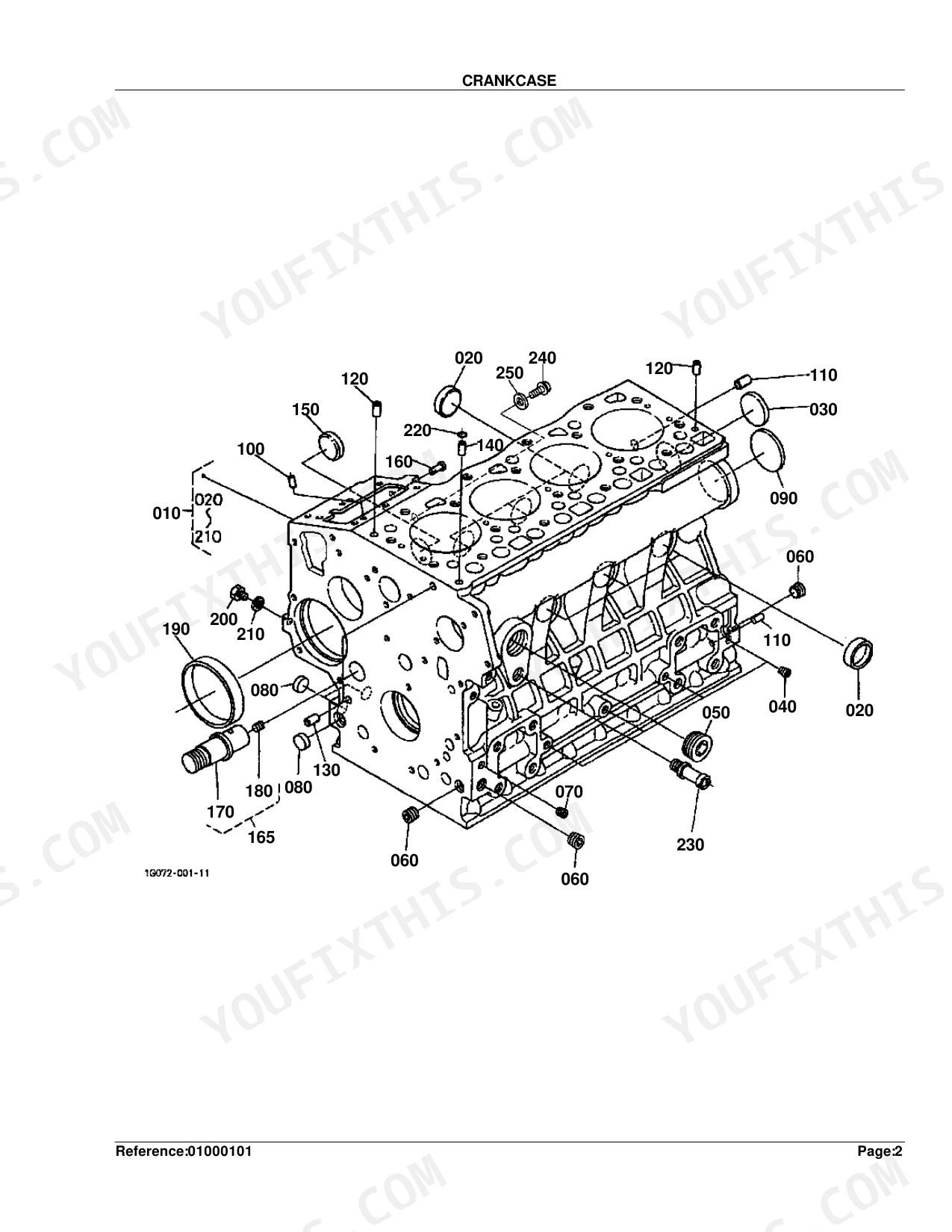
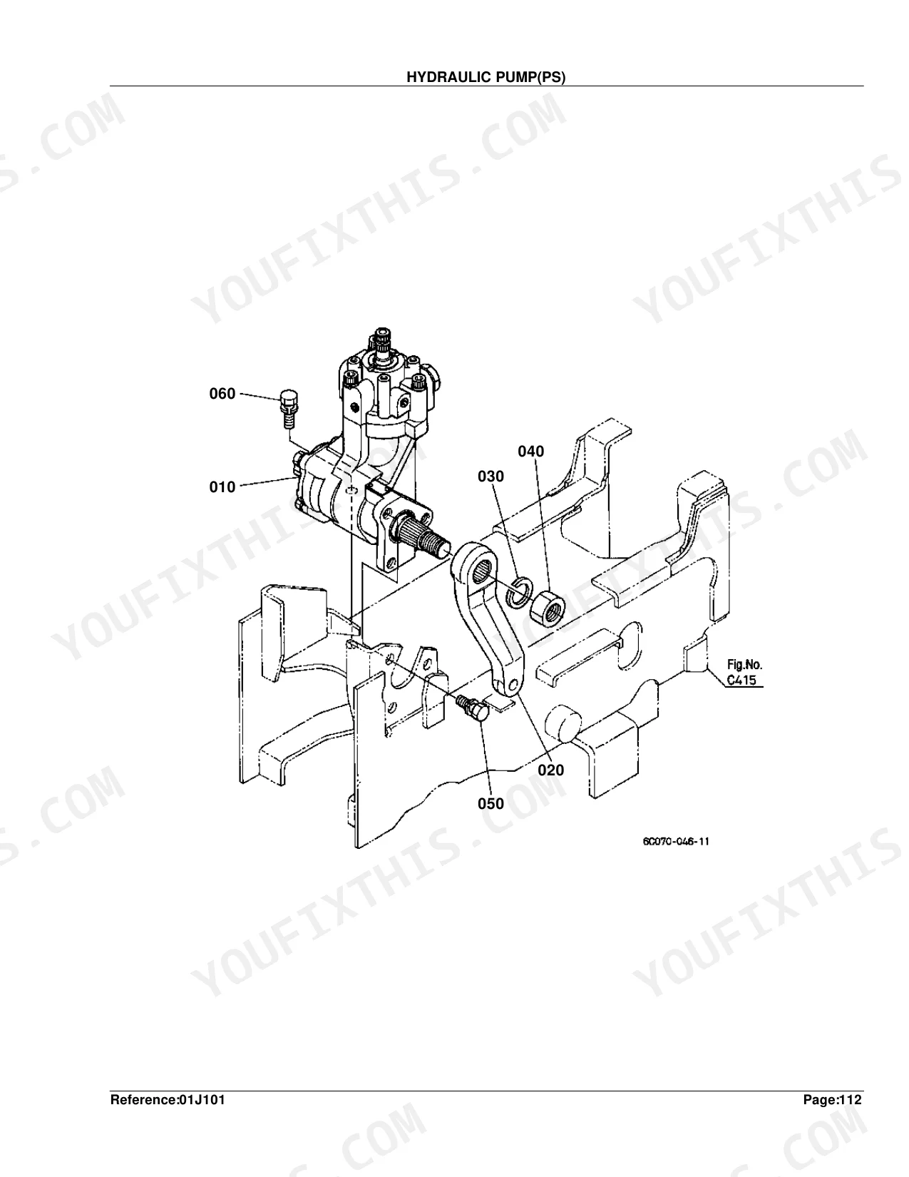
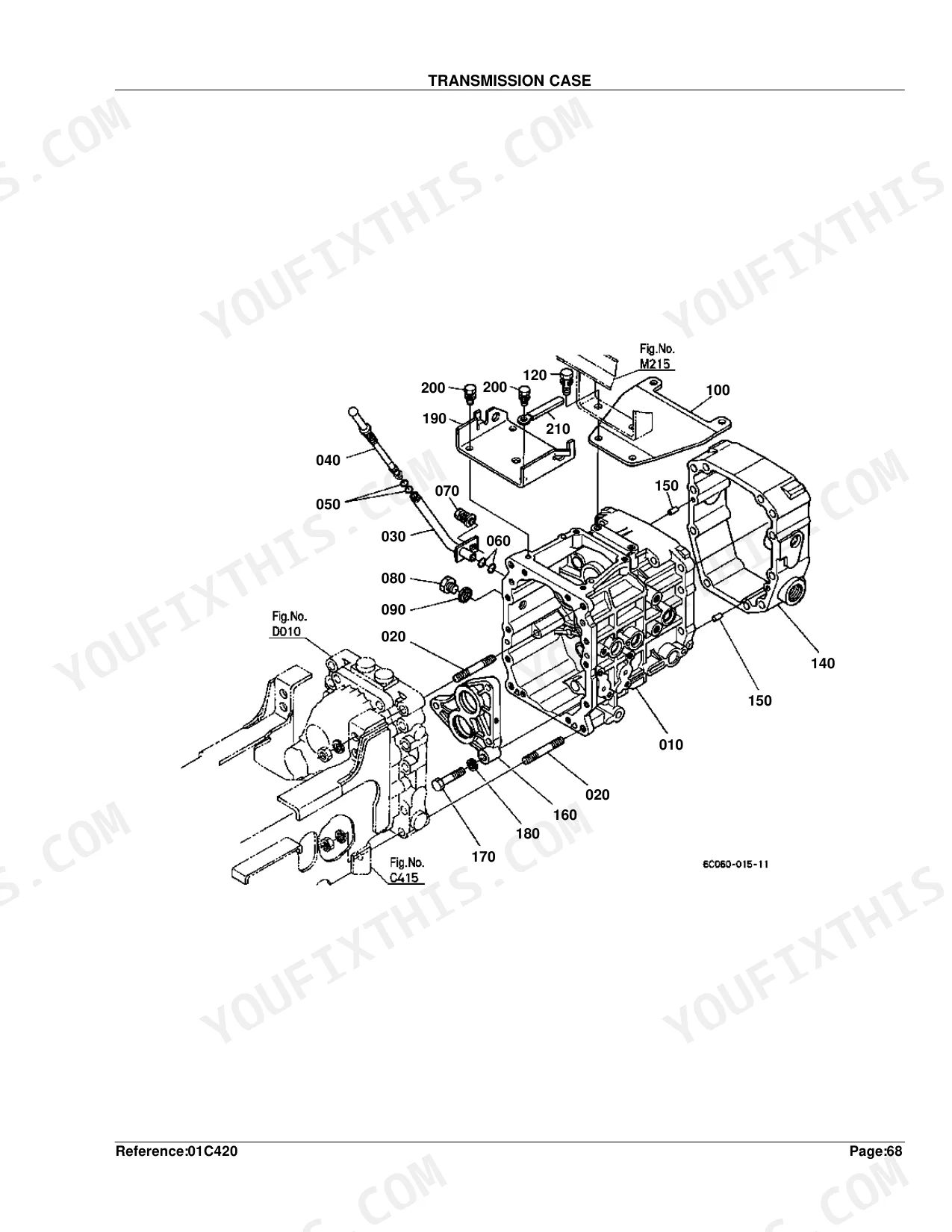
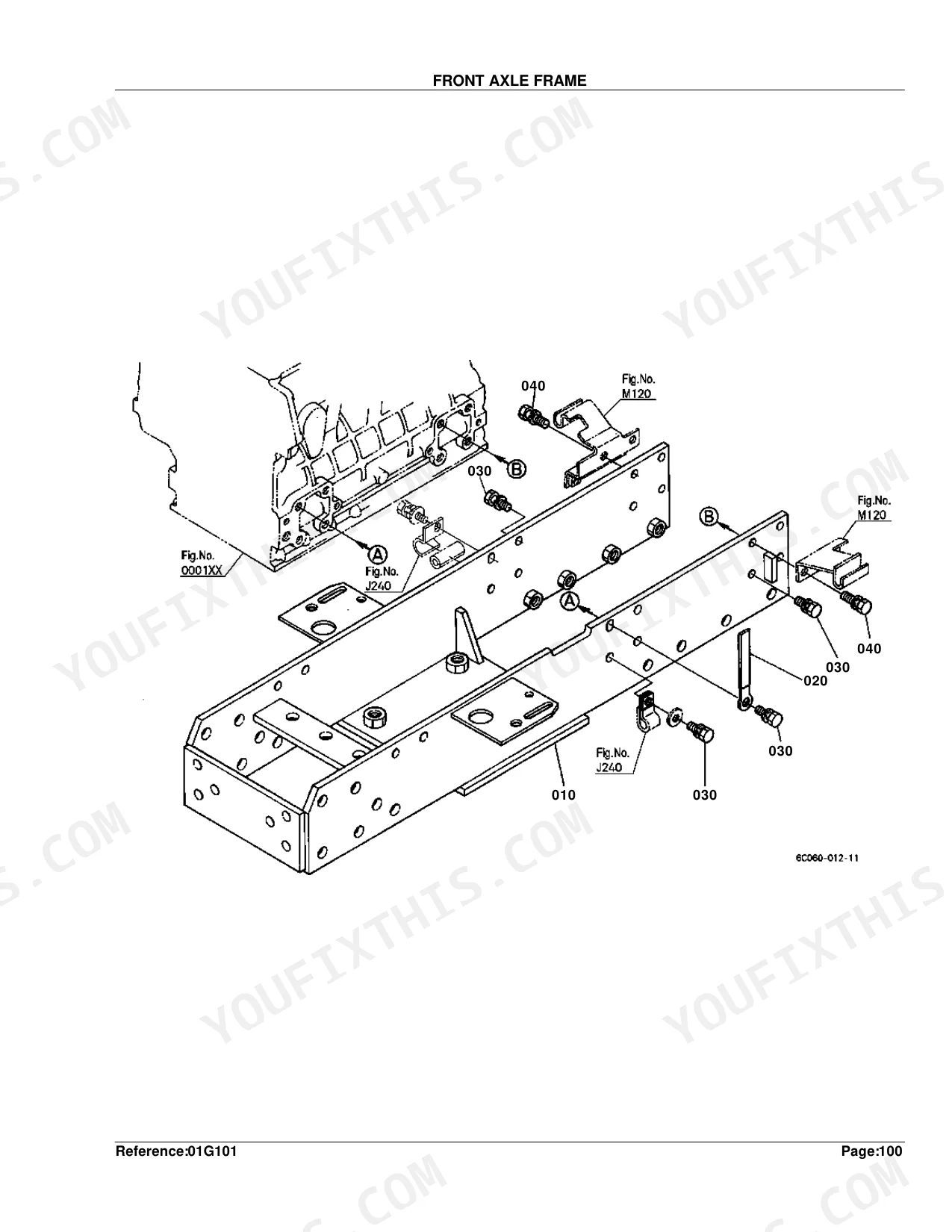
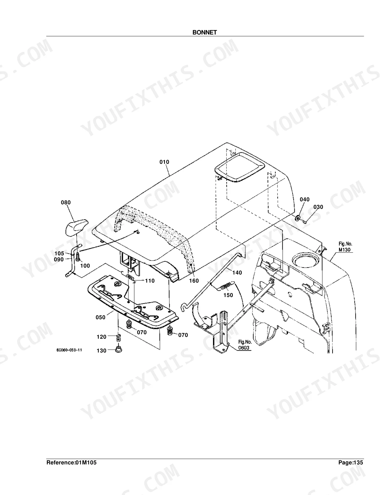
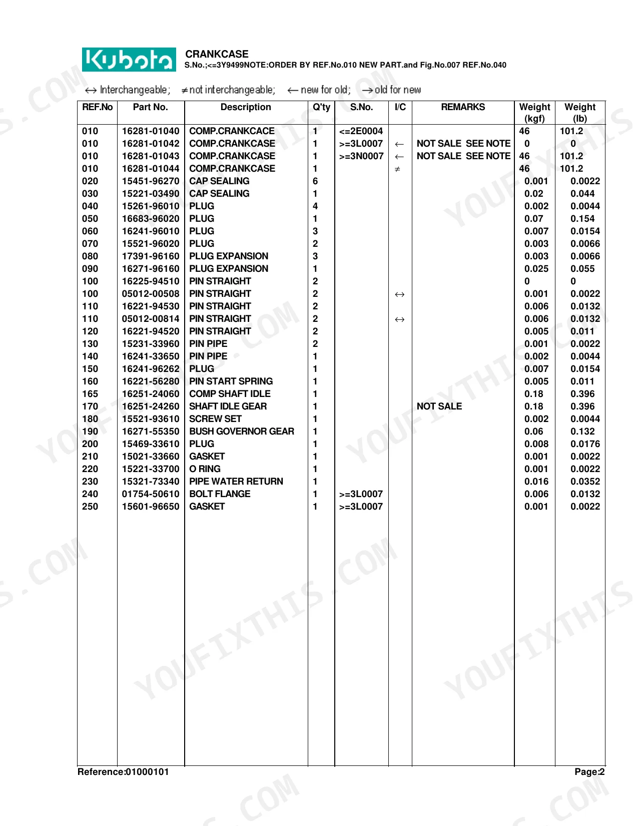
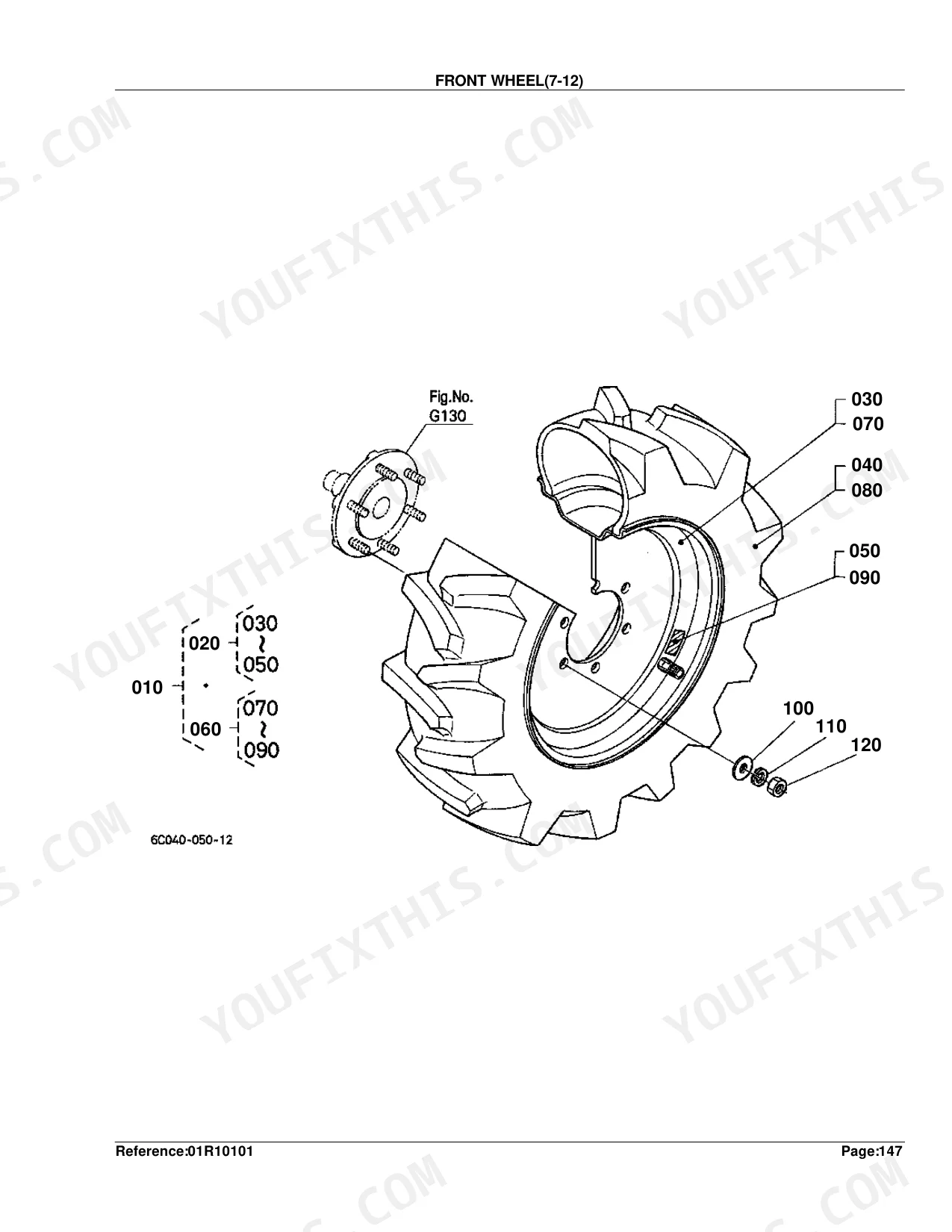
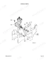
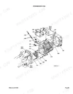
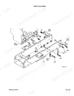
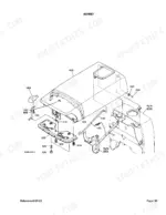
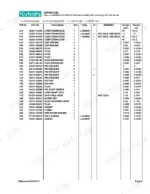
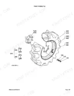
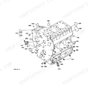
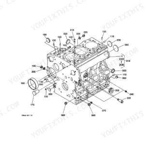
Finding the right part number before you drive to the counter is what this 332-page Kubota B7800HSD Parts Catalog is built to do. It breaks down into 69 pages of exploded parts lists across every engine subsystem from crankcase to exhaust manifold, 26 pages of drivetrain diagrams covering the HST unit, rear differential, and all four transmission shafts, and 36 pages of hydraulic parts diagrams mapping pump assemblies, oil line routing, and control valve parts. Every assembly pairs a labeled exploded view with a numbered parts list, quantity column, serial number applicability, and interchangeability codes, so you can tell which superseded part fits your machine. Component weights appear as reference data: 46 kgf for the crankcase, 12.1 kgf for the cylinder head, 0.4 kgf for a piston. Bookmarked by system, searchable by keyword, and ready on any device when you need to order.
What's Inside This Kubota B7800HSD Parts Manual
| System | Pages |
|---|---|
| Crankcase | 7-11 |
| Oil Pan | 12-13 |
| Cylinder Head | 14-16 |
| Gear Case | 17-18 |
| Head Cover | 19-22 |
| Oil Filter | 23-24 |
| Dipstick and Guide | 25-26 |
| Main Bearing Case | 27-28 |
| Camshaft and Idle Gear Shaft | 29-30 |
| Piston and Crankshaft | 31-34 |
| Flywheel | 35-36 |
| Fuel Camshaft and Governor Shaft | 37-38 |
| Idle Apparatus | 39-41 |
| Injection Pump | 42-43 |
| Governor | 44-47 |
| Speed Control Plate | 48-49 |
| Nozzle Holder and Glow Plug | 50-53 |
| Nozzle Holder [Component Parts] | 54-57 |
| Fuel Pump (Mechanical) | 58-59 |
| Water Flange and Thermostat | 60-61 |
| Water Pump | 62-63 |
| Valve and Rocker Arm | 64-65 |
| Inlet Manifold | 66-69 |
| Exhaust Manifold | 70-71 |
| Air Cleaner | 72-73 |
| Muffler | 74-75 |
| Upper Gasket Kit | 76-79 |
| Lower Gasket Kit | 80-81 |
| Accelerator Lever | 82-83 |
| Fuel Tank | 84-85 |
| Fuel Pipe | 86-88 |
| Fuel Filter [Component Parts] | 89-90 |
| Fan | 91-93 |
| Water Pipe | 94-95 |
| Radiator | 96-98 |
| Reserve Tank | 99-100 |
| Stop Solenoid | 101-103 |
| Dynamo | 104-106 |
| Dynamo [Component Parts] | 107-108 |
| Starter | 109-110 |
| Starter [Component Parts] | 111-112 |
| Battery | 113-115 |
| Switch [Mid PTO Type] | 116-119 |
| Switch [Except Mid PTO Type] | 120-123 |
| Panel Board | 124-125 |
| Panel Board [Component Parts] | 126-127 |
| Head Light | 128-129 |
| Hazard Light | 130-131 |
| Tail Light | 132-133 |
| Winker Lamp | 134-135 |
| Electrical Wiring | 136-138 |
| Clutch | 139-140 |
| Clutch Rod | 141-142 |
| Clutch Pedal | 143-144 |
| Clutch Housing | 145-146 |
| Center Frame | 147-148 |
| Sub Frame | 149-150 |
| Transmission Case | 151-152 |
| Differential Gear Case | 153-154 |
| Rear Axle Case | 155-156 |
| Clutch Shaft | 157-158 |
| Propeller Shaft | 159-160 |
| HST | 161-162 |
| HST [Component Parts] | 163-168 |
| Front Shaft | 169-170 |
| PTO Shaft | 171-172 |
| Mid PTO [Mid PTO Type] | 173-174 |
| Mid PTO [Except Mid PTO Type] | 175-176 |
| Rear Differential | 177-178 |
| Front Wheel Propeller Shaft | 179-180 |
| 2nd Shaft | 181-182 |
| 3rd Shaft | 183-184 |
| 4th Shaft | 185-186 |
| Rear Axle | 187-188 |
| Brake | 189-190 |
| Brake Rod | 191-192 |
| Parking Brake Lever | 193-194 |
| Speed Set Lever | 195-196 |
| Neutral Holder Link | 197-198 |
| Speed Control Pedal | 199-200 |
| Range Gear Shift Lever | 201-202 |
| Front Wheel Drive Lever | 203-204 |
| PTO Gear Shift Lever [Mid PTO Type] | 205-206 |
| PTO Gear Shift Lever [Except Mid PTO Type] | 207-208 |
| Hydraulic Control Lever | 209-210 |
| Brake Pedal | 211-212 |
| Differential Lock Pedal | 213-214 |
| Front Axle Frame | 215-216 |
| Front Axle Case | 217-227 |
| Front Differential | 220-221 |
| Differential Gear Shaft | 222-223 |
| Bevel Gear Case | 224-225 |
| Front Axle | 228-229 |
| Front Drive Shaft | 230-231 |
| Drag Link | 232-233 |
| Tie Rod | 234-235 |
| Steering Handle | 236-237 |
| Steering Post | 238-239 |
| Hydraulic Pump (PS) | 240-241 |
| Hydraulic Pump (PS) [Component Parts] | 242-243 |
| Hydraulic Pump | 244-245 |
| Hydraulic Pump [Component Parts] | 246-247 |
| Hydraulic Oil Line (Suction) | 248-249 |
| Hydraulic Oil Line (Delivery) | 250-251 |
| Hydraulic Oil Line (Steering) | 252-253 |
| Hydraulic Oil Line (T/M) | 254-255 |
| Hydraulic Oil Line (HST) | 256-257 |
| Hydraulic Oil Line (Oil Cooler) | 258-260 |
| Hydraulic Oil Line (F/M) | 261-262 |
| Hydraulic Cylinder | 263-264 |
| Hydraulic Piston/Lift Arm | 265-266 |
| Feed Back Lever | 267-269 |
| Control Valve | 270-271 |
| Control Valve [Component Parts] | 272-273 |
| 3-Point Linkage 2 (Lift Rod) | 274-275 |
| Lower Link | 276-277 |
| 3-Point Linkage 1 (Top Link) | 278-279 |
| Check Chain | 280-281 |
| Hitch/Drawbar | 282-283 |
| PTO Protector | 284-285 |
| Front Grille | 286-287 |
| Bonnet | 288-289 |
| Panel Cover | 290-291 |
| Side Cover | 292-293 |
| Shutter Plate | 294-296 |
| Fender | 297-299 |
| Floor Seat | 300-301 |
| Seat Support | 302-305 |
| Step | 306-307 |
| Rops (Rigid Type) | 308-309 |
| Rops (Foldable Type) | 310-311 |
| Smv Emblem | 312-314 |
| Front Wheel (7-12) | 315-316 |
| Front Wheel (23*8.50-12) | 317-318 |
| Front Wheel (23*8.50-14R4) | 319-320 |
| Front Wheel (24*8.50-14) | 321-322 |
| Rear Wheel (12.4-16) | 323-324 |
| Rear Wheel (13.6-16) | 325-332 |
| Rear Wheel (12.4-16R4) | 327-328 |
Every system also includes interchangeability symbols definition, a diagram, and a parts list.
Quick Reference Specifications
| Specification | Value | Page |
|---|---|---|
| Crankcase Weight | 46 kgf (101.2 lb) | p. 8 |
| Oil Pan Weight | 1.7 kgf (3.74 lb) | p. 13 |
| Cylinder Head Weight | 12.1 kgf (26.62 lb) | p. 16 |
| Oil Filter Weight | 0.4 kgf (0.88 lb) | p. 24 |
| Piston (STD) Weight | 0.4 kgf (0.88 lb) | p. 33 |
| Piston (+0.5mm) Weight | 0.415 kgf (0.913 lb) | p. 33 |
| Crankshaft Weight | 5 kgf (11 lb) | p. 33 |
| Flywheel Weight | 17.3 kgf (38.06 lb) | p. 36 |
| Injection Pump Shim Thickness | 0.20mm | p. 43 |
| Valve Inlet Weight | 0.005 kgf (0.011 lb) | p. 65 |
| Radiator Weight | 3.5 kgf (7.7 lb) | p. 98 |
| Battery Bracket Weight | 2.25 kgf (4.95 lb) | p. 115 |
Kubota B7800HSD Common Problems This Manual Covers
Kubota B7800HSD turns over but won't start, suspecting a failed fuel shutoff solenoid or blown fuse. p. 101
Check the stop solenoid exploded view on page 101. Locate the correct replacement solenoid part number for your specific serial number. Verify the battery bracket, weighing 2.25 kgf (4.95 lb) on page 115, is securely mounted to prevent wiring harness chafing.
Manual Section: Stop SolenoidHydrostatic transmission loses drive power after warming up, needing internal replacement components. p. 163
Inspect the HST component parts diagram on page 163 to pin down the internal seals and relief valves you need. Cross-reference the hydraulic oil filter part number on page 23 and swap the 0.4 kgf (0.88 lb) filter during the fluid change.
Manual Section: HST [Component Parts]Cranking but engine will not fire due to restricted fuel flow or damaged injection pump shims. p. 42
Trace the injection pump breakdown on page 42 to identify the exact pump assembly, then order the 0.20mm injection pump shim shown on page 43 to restore timing. Check the fuel filter component parts list on page 89 while you're at it.
Manual Section: Injection PumpUneven pulling in four-wheel drive with popping noises from the front drive assembly. p. 217
Examine the front axle case parts diagram on page 217 for damaged internal gears or bearings. Match the parts against the front drive shaft illustration on page 230, and replace the 3.5 kgf (7.7 lb) radiator on page 98 if debris has wrecked it.
Manual Section: Front Axle CaseFrequently Asked Questions
What causes a Kubota B7800 no-start fuel cut-off or solenoid problem?
As a parts catalog, it won't diagnose what causes a no-start fuel cut-off or solenoid fault, but it does list the parts involved: ASSY SOLENOID STOP (Part No. 17208-60010) and SOLENOID STOP (Part No. 32721-60010) within the fuel shutoff system.
What are the replacement specifications for fuel filter?
The fuel filter replacement is the ASSY FILTER FUEL, Part No. 6A320-58862, at 0.09 kgf (0.198 lb). Inside that assembly, the FILTER (Part No. 6A320-59930) is a component part weighing 0.025 kgf (0.055 lb).
What are the replacement specifications for fuse?
Several fuse specifications are listed for the electrical wiring. A 30A FUSE (Part No. 1G111-65720) weighs 0.009 kgf (0.0198 lb), a 5A FUSE AUTO (Part No. 66426-80010) weighs 0.01 kgf (0.022 lb), and a 10A FUSE AUTO (Part No. 36730-75550 or 48100-55880) weighs 0.001 kgf (0.0022 lb) or 0.01 kgf (0.022 lb) respectively.
How will I receive this Kubota B7800HSD Parts Catalog?
Download is instant. The full 332-page searchable Parts Catalog is yours immediately after payment, ready on a laptop, tablet, or phone out in the shop.
Is this Kubota B7800HSD Parts Catalog printable?
None at all. The PDF is DRM-free, so print whatever sections you want to take out to the shop. Standard letter or A4 paper works.
Are there hydraulic schematics in this Kubota B7800HSD manual?
This is a parts catalog, so it shows exploded parts diagrams rather than circuit schematics. It includes detailed exploded views of the hydraulic components — pump, control valve, cylinder, and oil lines — with OEM part numbers, not wiring-style circuit diagrams.
Document Quality
This document is a scanned PDF with an OCR layer, allowing you to search and copy most text, which is generally crisp and easy to read. However, some special characters in the 'I/C' column appear as OCR artifacts, and text directly on diagrams is not searchable. The diagrams and illustrations are raster images, clear enough for identifying parts and reading labels, but they will pixelate if zoomed in significantly. Pages are consistently clean with no noticeable scan artifacts, stains, or skewed content. You will find specific 'OLD PARTS' pages with diagrams, which serve as content rather than blank filler.


Reviews
There are no reviews yet.