
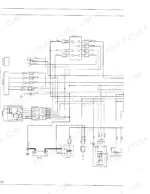
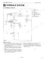
Kubota built the L2050 around a vertical water-cooled 3-cylinder diesel and a Category I 3-point hitch, and this OEM manual (#60350-0) documents every bolt of it across 316 pages, whether you run the 2WD or 4WD version. The breakdown: wiring diagrams, hydraulic schematics tracing oil flow through the power steering and 3-point hitch circuit, and troubleshooting for the engine, 8-speed transmission, wet disc brakes, and rear axle. Add torque tables, exploded-view diagrams, and separate sections for the BF400 loader and RC60-20 mower. Cylinder head bolts go to 88.3-92.2 N·m, clutch pedal free play sits at 20-30 mm, and oil pump rotor clearance runs 0.10-0.16 mm. Stop guessing at Kubota's numbers. Search any keyword, jump to the section you need, and read it on your phone at the machine.
What's Inside This Kubota L2050 Manual
| System | Pages | Key Topics |
|---|---|---|
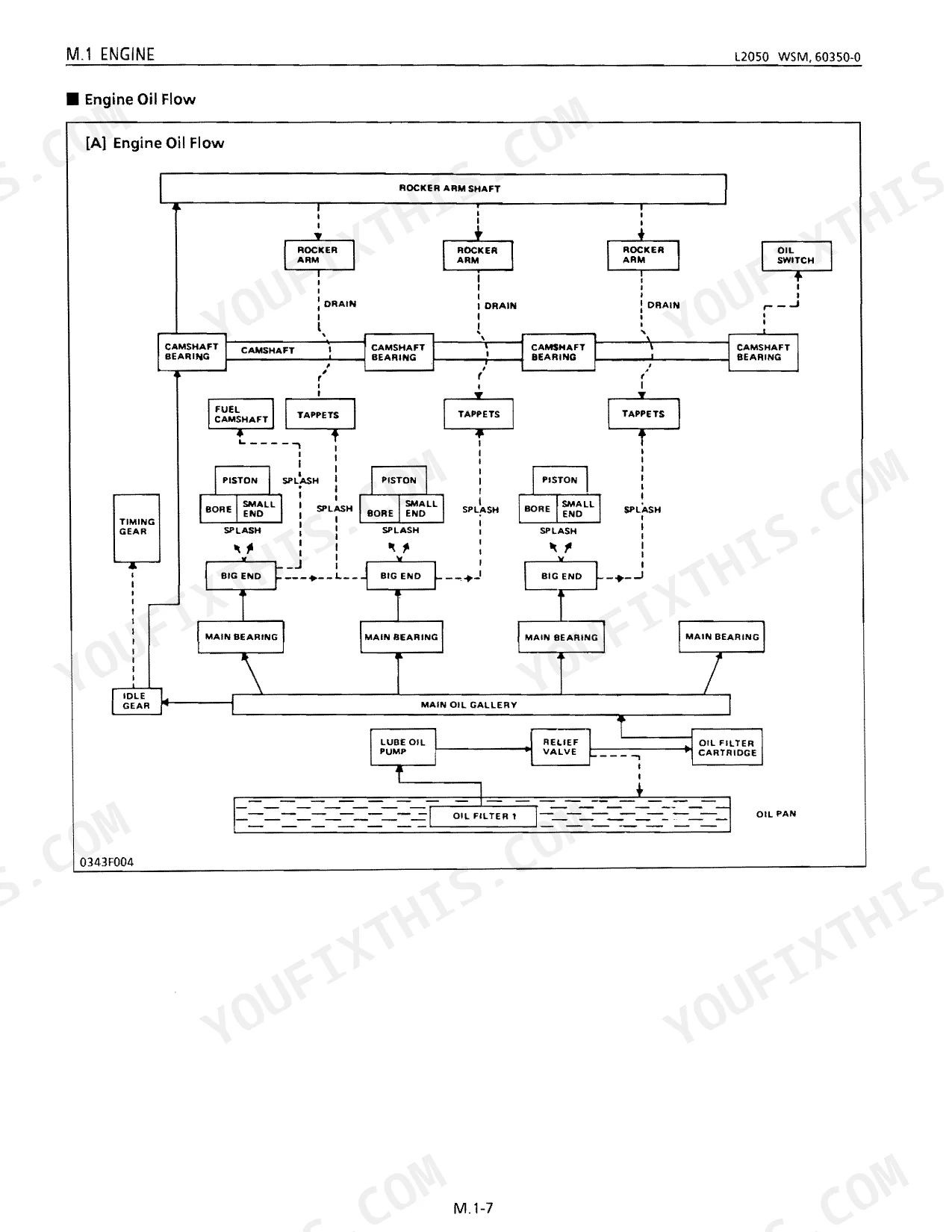
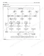
| Mechanism | 4-66 | Engine, Transmission, Power Train, Front Wheel Drive Section, Front Axle, Steering, Power Steering, Oil Flow |
| General | 67-90 | Tractor Identification, Lubricants, Tightening Torques, Maintenance Check List, Check Points (Initial 35/50 Hours) |
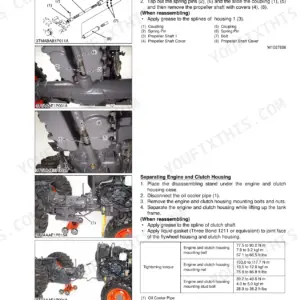
| Separation | 91-100 | Tightening Torques, Draining Oil And Coolant, Separating Front Axle, Separating Engine From Clutch Housing, Separating Engine, Separating Clutch Housing |
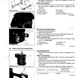
| Sect 1 Engine | 101-138 | Engine Body, Cylinder Head, Crankshaft, Piston, Lubricating System, Cooling System, Fuel System |
| Sect 2 Clutch | 139-144 | Clutch Disc, Pressure Plate, Release Hub, Clutch Lever, Pilot Bearing, Clutch Pedal |
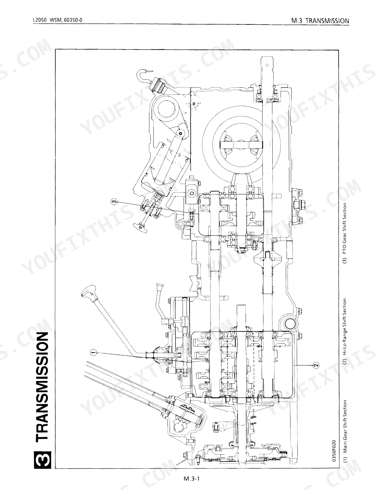
| Sect 3 Transmission | 145-156 | Clutch Housing Case, Transmission Case, Main Gear Shift, Range Gear Shift |
| Sect 4 Rear Axle | 157-162 | Differential Gear, Rear Axle, Final Gear, Bevel Pinion |
| Sect 5 Brakes | 163-168 | Brake Disc, Cam Plate, Brake Cam, Brake Pedal, Brake Pedal Shaft, Support Bushing |
| Sect 6 Front Axle | 169-174 | Front Axle Middle Boss, Knuckle Shaft, Front Wheel Hub, Tie Rod End, Bracket Bushing |
| Sect 7 Steering | 175-178 | Sector Shaft, Ball Nut, Pitman Arm, Thrust Ball Bearing, Tie Rod End, Steering Wheel |
| Sect 8 Hydraulic | 179-190 | Hydraulic Pump, Control Valve, Relief Valve, Cylinder Safety Valve, Hydraulic Cylinder |
| Sect 9 Electrical | 191-216 | Battery, Starting System, Charging System, Lighting System, Wiring Diagram |
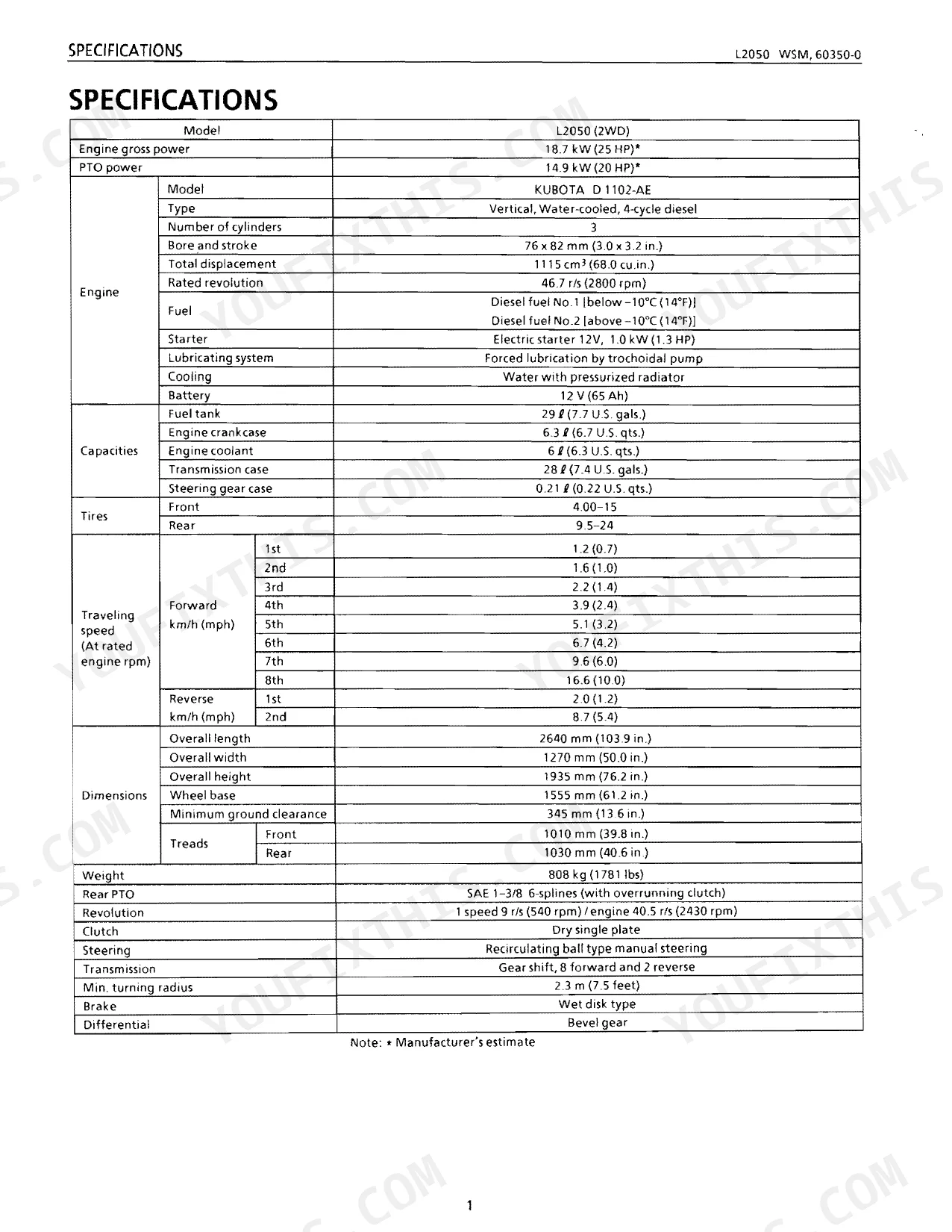
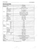
| Supplement L2050Dt | 263-316 | Specifications (Model, Engine gross power, PTO power, Engine, Capacities, Tires, Traveling speed, Dimensions, Weight, Rear PTO, Revolution, Clutch, Steering, Min turning radius, Brake, Differential) |
Quick Reference Specifications
| Specification | Value | Page |
|---|---|---|
| Cylinder head screws and nuts | 88.3 to 92.2 N·m | p. 110 |
| Clutch Pedal Free play | 20 to 30 mm | p. 140 |
| Inner Rotor to Outer Rotor Clearance | 0.10 to 0.16 mm | p. 108 |
| Fuse blown | 10A | p. 192 |
| Fan Belt Tension | 7 mm | p. 108 |
| Commutator O.D. | 29.9 to 30.0 mm | p. 193 |
| Brake Pedal Free Play | 30 to 40 mm | p. 163 |
| Radiator Water Tightness | Water tightness at specified pressure 88 kPa | p. 108 |
| Thermostat Valve Opening Temperature At Begining | 80.5° to 83.5°C | p. 109 |
| Engine gross power | 18.7 kW (25 HP) | p. 1 |
| Fuel tank capacity | 29 L (7.7 U.S. gals.) | p. 1 |
| Engine crankcase capacity | 6.3 L (6.7 U.S. qts.) | p. 1 |
Kubota L2050 Common Problems This Manual Covers
Kubota L2050 engine overheating, temperature gauge climbing, coolant loss after extended field work p. 101
Start with fan belt tension: deflection at midspan must be 7 mm. Clear the radiator passages of debris, then pressure-test the cooling system at 88 kPa (page 108). Pull the thermostat and bench-test it; it should begin opening between 80.5° and 83.5°C (page 109). Work through the overheating diagnosis on page 101 before you pull the head.
Manual Section: Sect 1 EngineClutch slips under heavy draft load, drags when released, or chatters on engagement p. 139
Measure clutch pedal free play at the pedal pad: factory spec is 20 to 30 mm (page 140). If play is correct but the clutch still slips, the disc and pressure plate likely need replacement. Disassemble per the procedures on page 139. Inspect disc thickness and check the pressure plate surface for glazing or hot spots before reassembly.
Manual Section: Sect 2 ClutchImplement won't reach full lift height or drops slowly when the hydraulic lever is released p. 179
Inspect the hydraulic fluid level and condition first. Verify the cylinder safety valve is set to 19.61 to 20.58 MPa (2844 to 2986 psi) per page 38. If pressure tests out, check the hydraulic pump: inner rotor to outer rotor clearance limit is 0.10 to 0.16 mm (page 108). Work through the implement-not-rising and implement-dropping charts on page 179.
Manual Section: Sect 8 HydraulicEngine won't crank, starter motor silent or clicks once in cold or damp conditions p. 191
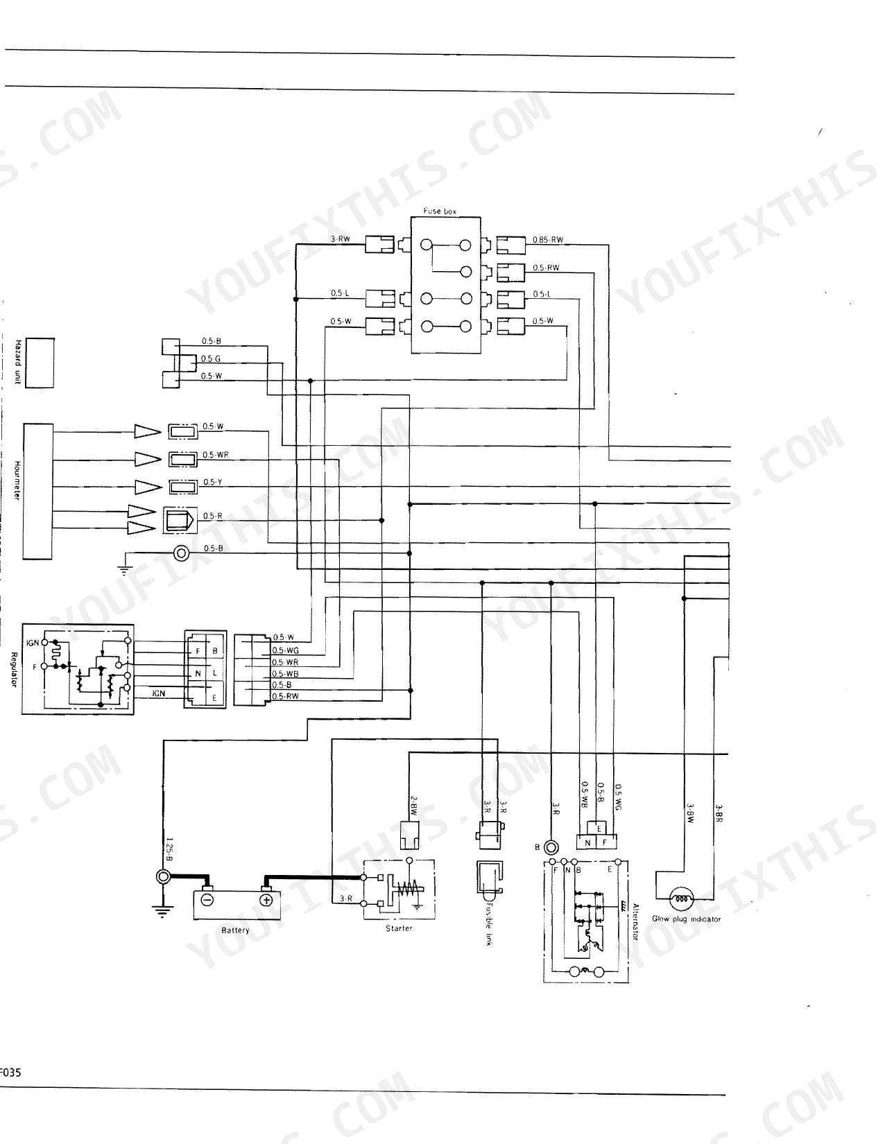
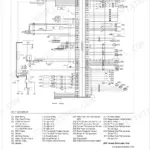
Begin at the fuse block; the main fuse is 10A (page 192). Test battery voltage and load capacity before you suspect the starter. If the starter spins but won't engage, measure commutator O.D.: the service limit is 29.9 to 30.0 mm (page 193). Trace the wiring connections against the diagram before condemning the starter or charging system.
Manual Section: Sect 9 ElectricalOne brake grabs harder than the other or both pedals feel spongy underfoot p. 163
Adjust brake pedal free play to 30 to 40 mm (page 163) on both sides; unequal free play is the first thing to check when braking pulls. If adjustment doesn't resolve it, disassemble per the procedures on page 163 and inspect lining thickness and drum contact surfaces. Verify both pedals equalize before testing on level ground.
Manual Section: Sect 5 BrakesGears grind on the shift into second, or a gear pops out of mesh under load p. 145
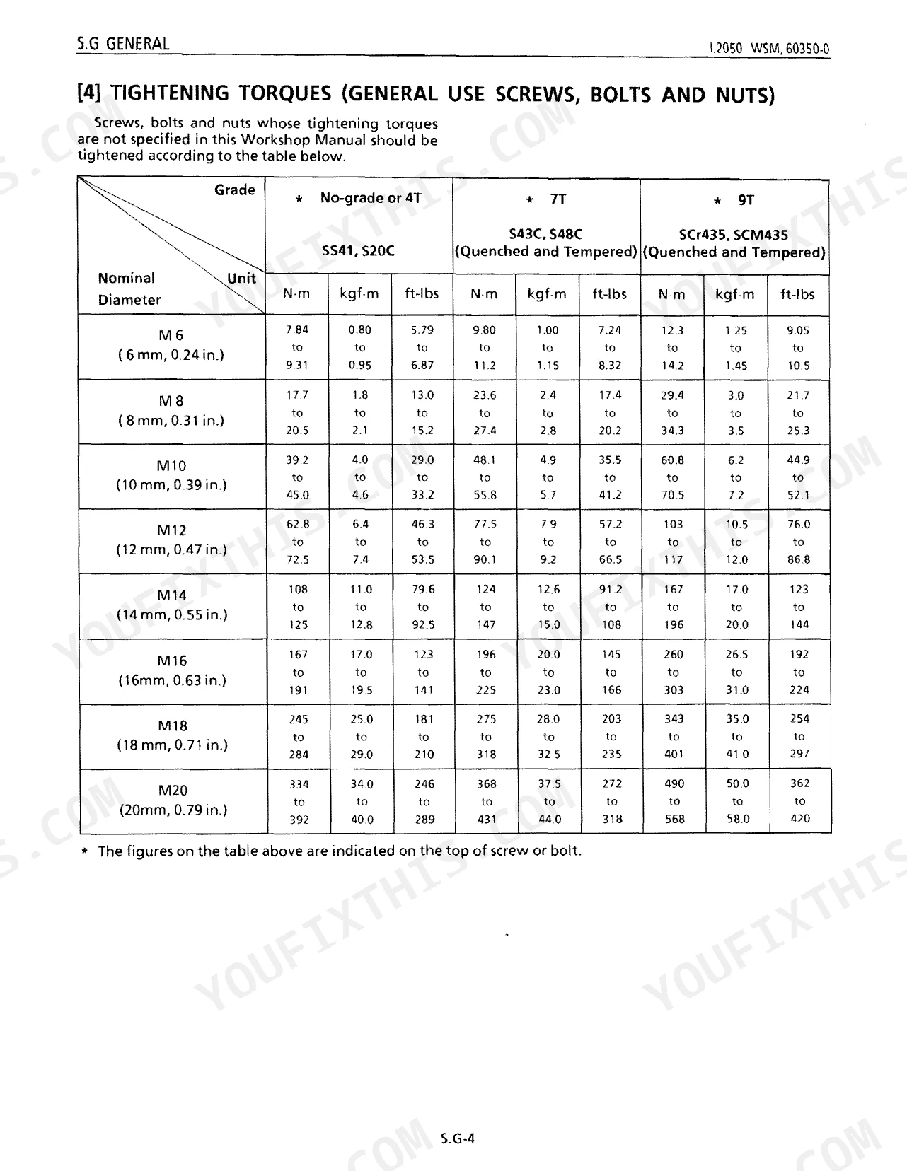
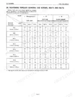
Confirm transmission oil level and condition before disassembly; contaminated oil accelerates synchronizer wear on this model. Run through the noise and gear-slip-out-of-mesh chart on page 145. Inspect shift fork wear and engagement dogs for rounding. Torque all case fasteners to M10 (7T) spec, 48.1 to 55.8 N·m (35.5 to 41.2 ft-lbs), during reassembly (page 70).
Manual Section: Sect 3 TransmissionFrequently Asked Questions
How do I troubleshoot a Kubota L2050 that won’t start?
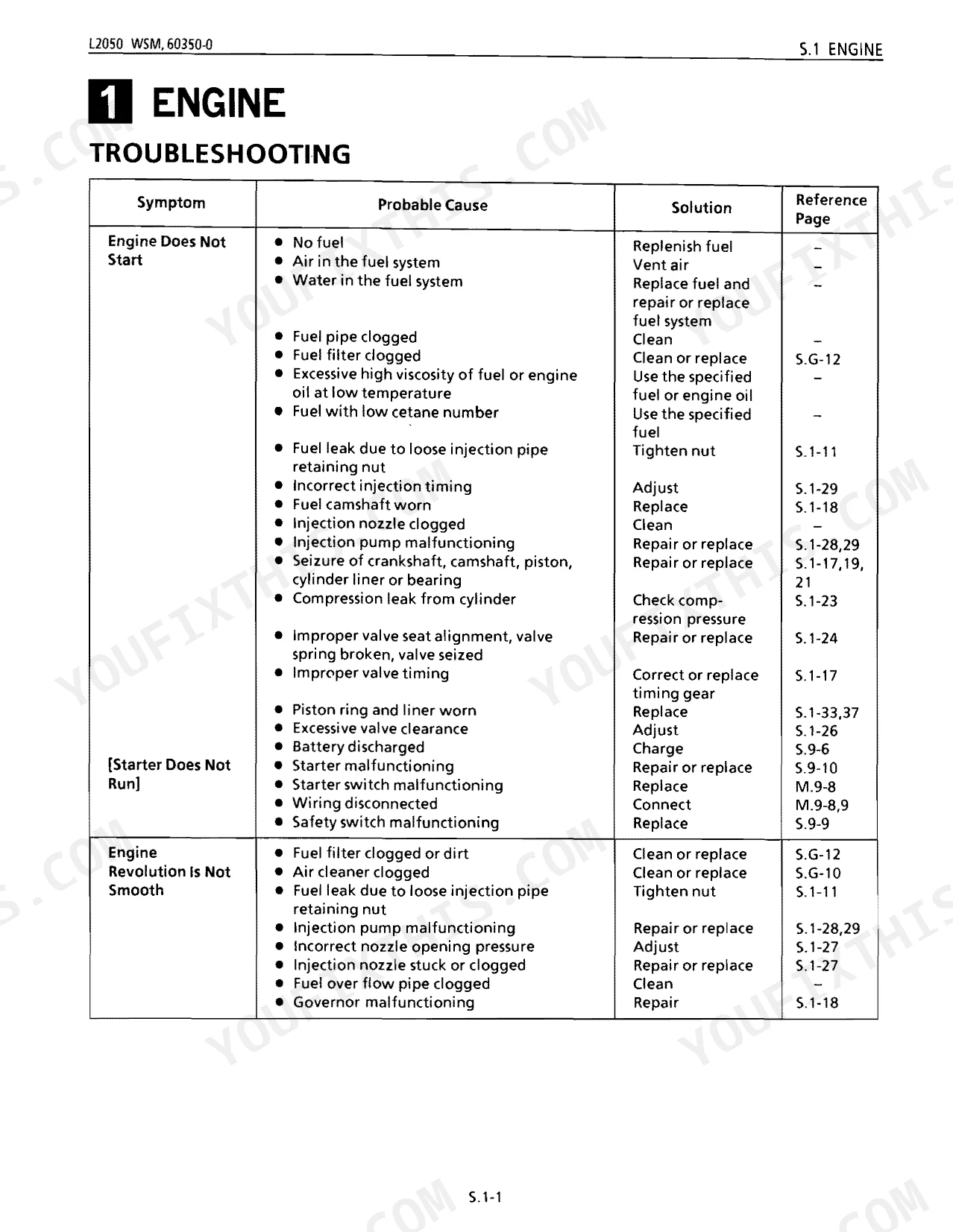
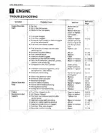
Start with the basics: no fuel means you simply replenish the tank, and a fuel leak from a loose injection pipe retaining nut just needs the nut tightened. Incorrect injection timing calls for adjustment on page S.1-29. A compression leak from the cylinder means you check the compression pressure, covered on page S.1-23.
What hydraulic fluid does a Kubota L2050 use?
The hydraulic system shares its oil with the transmission case, and both run multi-grade transmission fluid. That case holds 28 L (7.4 U.S. gals.). For specific brand names, see the 'LUBRICANTS' table on page S.G-3.
How do I bleed fuel on a Kubota L2050?
Bleeding the fuel system is the last step of the 'Replacing Fuel Filter Cartridge' procedure. Empty the fuel tank, remove the old filter cartridge, and install the new one, then bleed the system to finish.
Why does my Kubota L2050 turn over but not fire?
Cranking without firing usually points to fuel delivery. Incorrect injection timing needs adjustment (S.1-29), and a worn fuel camshaft needs replacement (S.1-18). A clogged injection nozzle is another suspect, as is a compression leak from the cylinder, which means checking the compression pressure (S.1-23).
How quickly can I access this Kubota L2050 manual after buying?
A 316-page service manual in searchable PDF, available the moment checkout completes. Open it on a computer, tablet, or phone with no shipping wait.
Can I print specific sections of this Kubota L2050 Service Manual?
Yes. There's no DRM or copy protection, so you can print the whole manual or just the pages you need on any home or office printer.
Does this Kubota L2050 manual include hydraulic schematics?
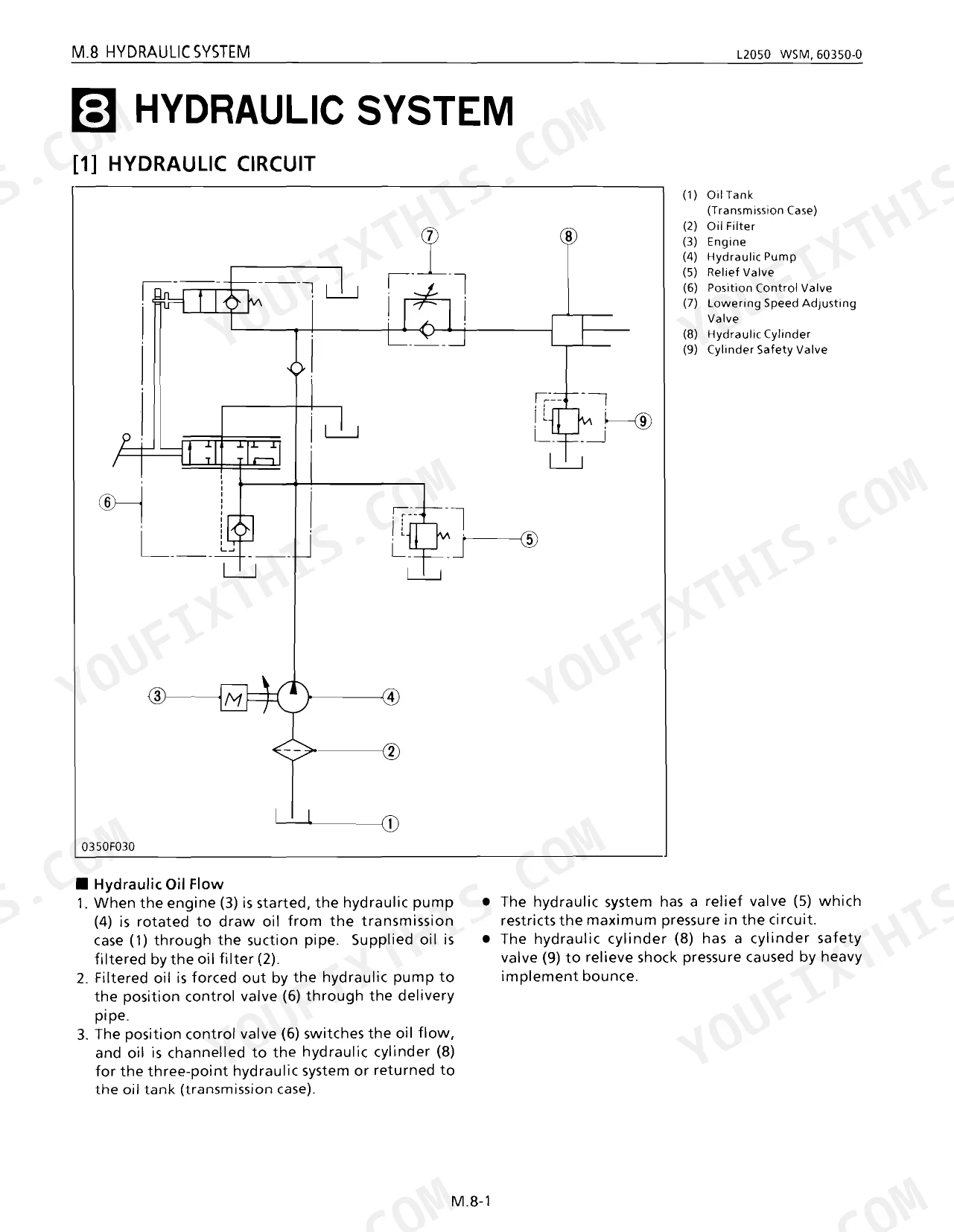
Full hydraulic system diagrams are included, covering circuits, valve locations, and hydraulic component specs for the Kubota L2050.
Document Quality
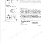
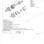
This document is a scanned PDF with an OCR text layer, allowing you to search and copy the full text. The text quality is consistently crisp and easy to read throughout. Diagrams and illustrations are primarily sharp line art, with all labels clearly legible, and some pages include clear photographs. Pages are clean, free of scan artifacts, stains, or skewed content. There are a few blank pages that act as section dividers.

Reviews
There are no reviews yet.