

Part of the Kubota Repair Manuals.
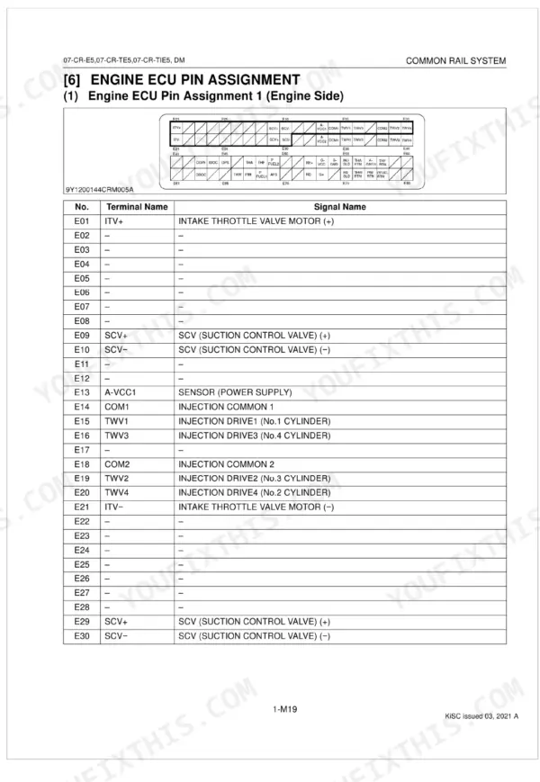
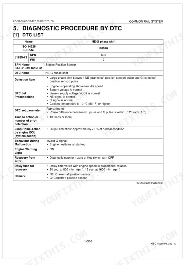
This Kubota Diagnostic Manual covers the 07-CR-E5, 07-CR-TE5, and 07-CR-TIE5 common rail diesel engines together with their DM diagnostic system. It is built around the electronic fuel system: wiring diagrams, engine ECU pin assignments, available data monitor signals, and the full diagnostic trouble code (DTC) procedures a technician needs to read a fault and repair it.
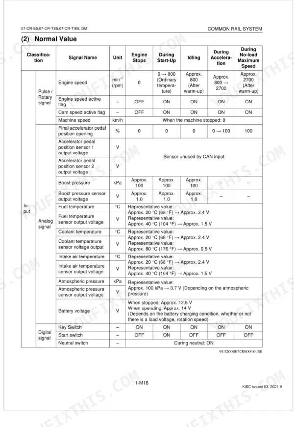
Across 371 pages you get the diagnosis flow organized by malfunction symptom, DTC-by-DTC test procedures, scan tool connection steps, and inspection procedures for the air intake, fuel, and electric systems. Reference values such as target rail pressure and suction control valve current give you the normal readings to check live data against.
If your engine throws a warning light, cranks too long, smokes, or loses power, this PDF walks you from the symptom to the exact circuit test, so you can pinpoint the cause instead of swapping parts on guesswork.
What's Inside This Kubota 07-CR-E5, 07-CR-TE5, 07-CR-TIE5, DM Manual
| System | Pages | Key Topics |
|---|---|---|
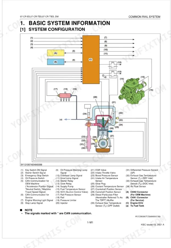
| Basic System Information | System Configuration | |
| Wiring Diagram | Engine Intermediate Harness, Injector Intermediate Harness, Engine ECU Intermediate Harness, System Wiring Diagram | |
| Available Data Monitor Signals | Available Data Monitor Signals (Monitor Items, Normal Value) | |
| Engine ECU Pin Assignment | Engine ECU Pin Assignment 1, Engine ECU Pin Assignment 2 | |
| General Diagnostics | General (Overall Diagnostic Procedure, Questioning, List of Malfunction Symptom, Actions for Non-Reoccurring Malfunctions) | |
| Diagnostic Tool Connection Procedure | Diagnostic Connector Positions, Checking the Communication Operation of the Interface, Checking the Operation of the Engine ECU | |
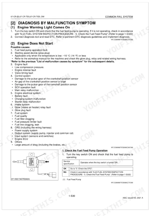
| Diagnosis by Malfunction Symptom | Engine Warning Light Comes on, Takes a Long Time Before Engine Starts, Idle Failure, Engine Noise, High Fuel Consumption, Poor Acceleration, Abnormal Black Smoke Emitted, Abnormal White Smoke Emitted | |
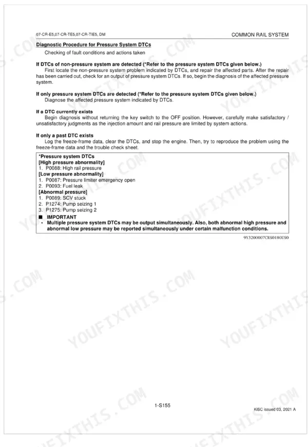
| Diagnostic Procedure by Dtc | Diagnostic Procedure by Dtc (Dtc List, Diagnostic Procedure by Dtc) | |
| Inspection Procedure for Each System | Inspection Procedure for Each System (Air Intake System Inspection Procedure, Fuel System Inspection Procedure, Electric System Inspection Procedure) |
Quick Reference Specifications
| Specification | Value | Page |
|---|---|---|
| Fuel filter replacement interval | every 500 operation hours | p. 363 |
| Pump difference learning correction value | must be within ± 200 mA | p. 184 |
| Resistance between injector terminals | 0.35 to 0.55 Ω | p. 223 |
| Engine Speed (Idling) | Approx. 800 rpm | p. 25 |
| Engine Speed (No-load Maximum) | Approx. 2700 rpm | p. 25 |
| Target Rail Pressure (Idling) | Approx. 30 MPa | p. 26 |
| Target Rail Pressure (No-load Maximum) | 95.0 to 115 MPa | p. 26 |
| Actual Suction Control Valve (SCV) Current (Idling) | Approx. 1800 mA | p. 26 |
| Intake Air Temperature Sensor Resistance (at 20 °C / 68 °F) | Approx. 2.43 kΩ | p. 173 |
| Coolant Temperature Sensor Resistance (at 20 °C / 68 °F) | Approx. 2.5 kΩ | p. 181 |
| Fuel Temperature Sensor Resistance (at 20 °C / 68 °F) | Approx. 2.5 kΩ | p. 187 |
| Injector Resistance | 1.5 Ω or lower | p. 216 |