


This is the Kubota L355SS parts catalog, the factory reference for identifying and ordering every component on the L355SS tractor. Across 225 pages it is organized by system, starting with the diesel engine (crankcase, cylinder head, camshaft, injection pump, and nozzle holders) and moving through the clutch, transmission, shuttle shift, differential, rear axle, brakes, hydraulics, three-point hitch, front axle, and the electrical system.Each part is shown on an exploded diagram and listed with its reference number, Kubota part number, description, and quantity, so you can pin down the exact piece and order the right replacement.For owners chasing common L355SS issues like starting and shuttle-shift faults, or simply keeping the tractor maintained, this catalog shows exactly what goes where. It is a searchable, printable PDF download that works on a bench computer or a phone.
What's Inside This Kubota L355SS Parts Manual
| System | Pages | Key Topics |
|---|---|---|
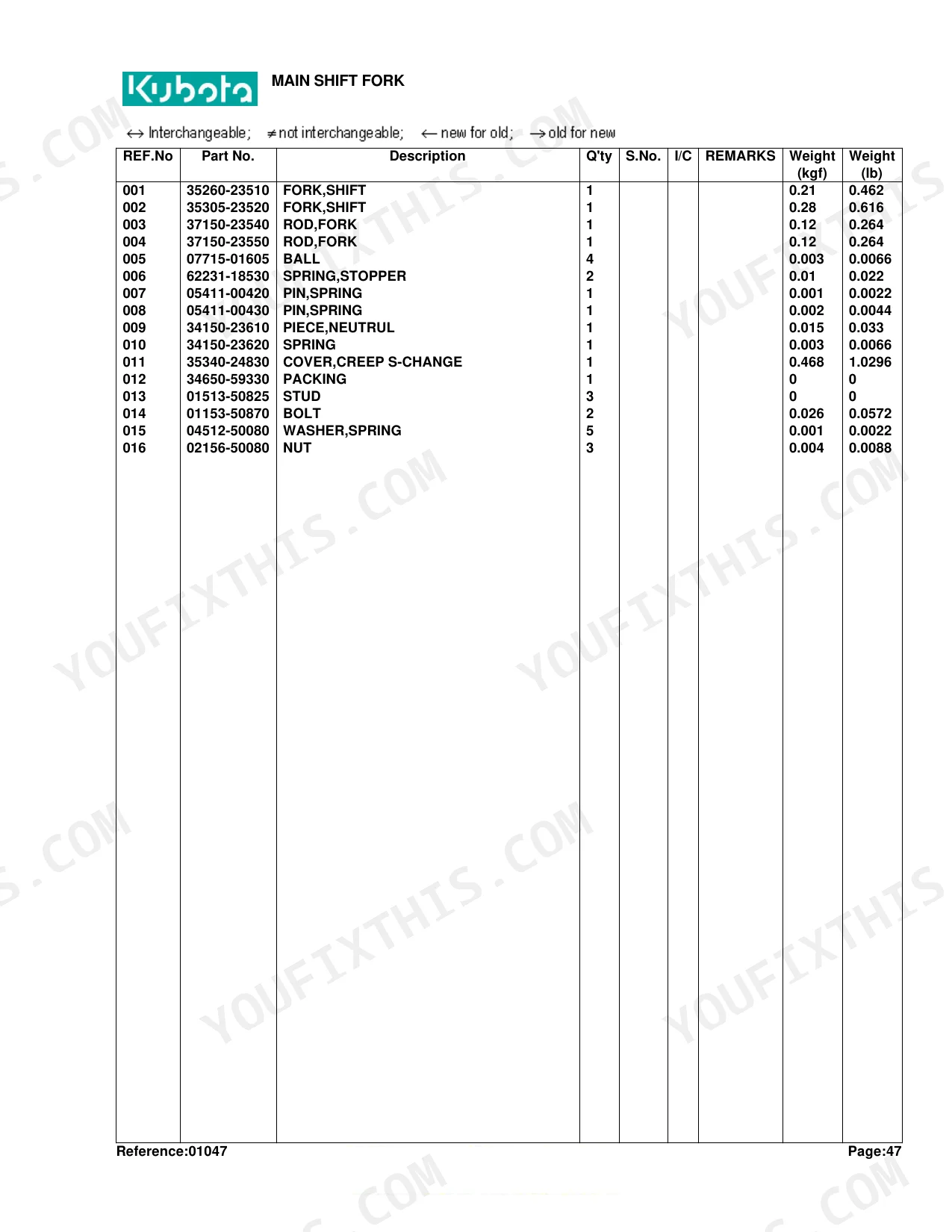
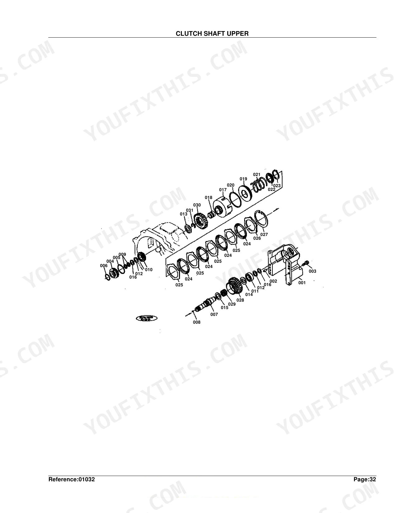
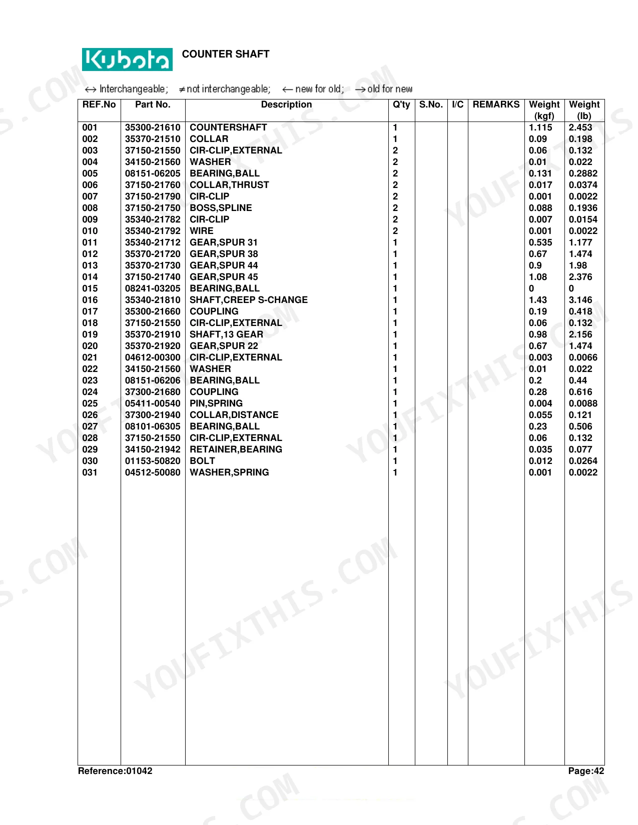
| Clutch & Transmission | Clutch Housing, Clutch Shaft Upper, Clutch Shaft Lower, Reverse Shaft, Clutch, Clutch Pedal, Transmission Case, Main Shaft, Counter Shaft, PTO Counter Shaft, Main Shift Lever, Main Shift Fork, Hi-Lo Gear Shift Lever, PTO Gear Shift Lever, Shuttle Lever | |
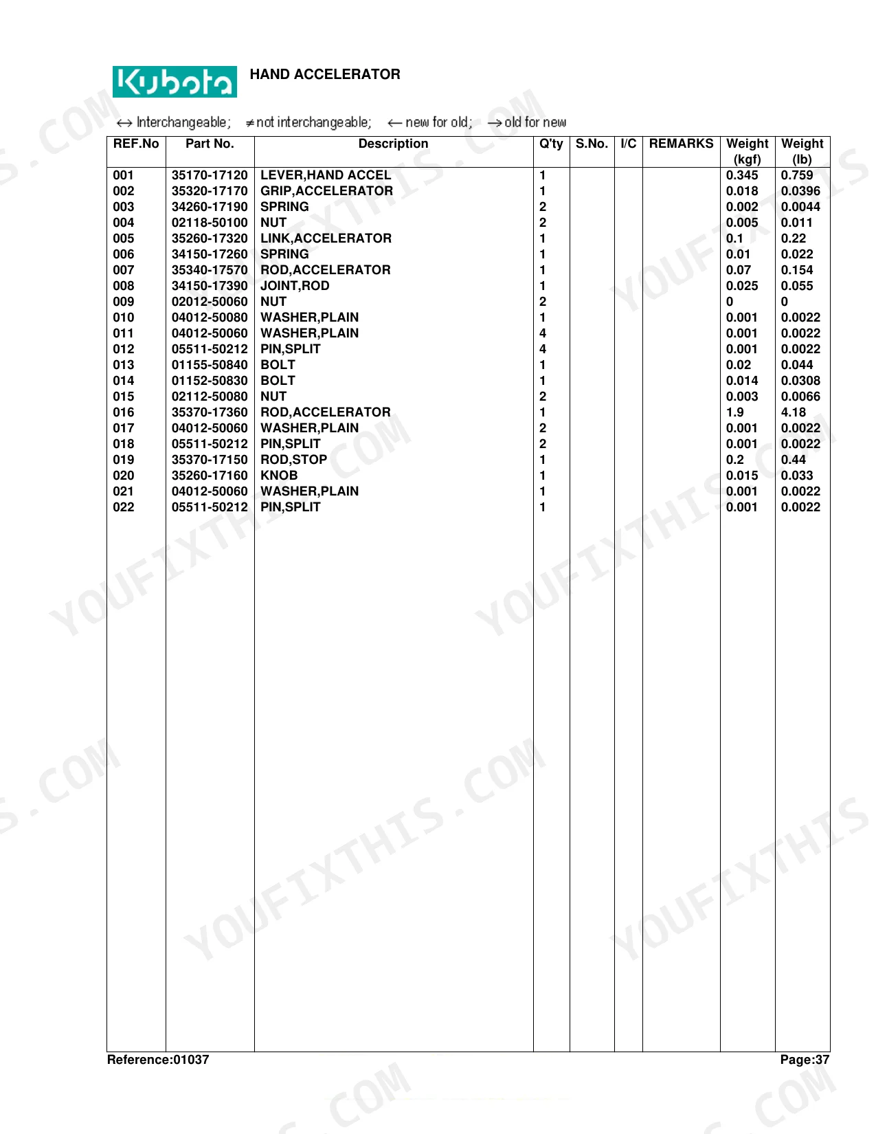
| Fuel System | Air Cleaner, Fuel Camshaft, Governor, Speed Control Plate, Engine Stop Lever, Injection Pump, Injection Pump Section Parts, Nozzle Holder, Nozzle Holder Section Parts, Air Cleaner Support, Hand Accelerator, Fuel Filter, Fuel Filter Section Parts, Fuel Tank | |
| Cooling System | Radiator, Water Pump | |
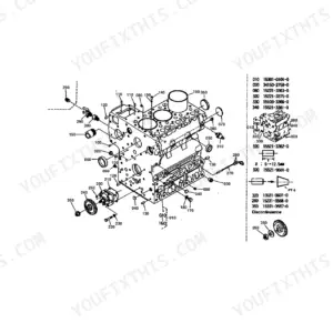
| Engine | Crankcase, Oil Pan, Cylinder Head, Gear Case, Main Bearing Case, Exhaust Manifold, Valve, Rocker Arm, Head Cover, Camshaft, Piston, Crankshaft, Flywheel, Flywheel Housing, Front Diff Gear Case, Upper Muffler | |
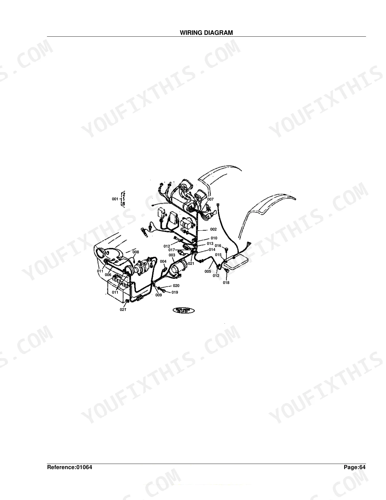
| Electrical System | Starter Section Parts, Dynamo, Dynamo Section Parts, Hour Meter and Switch, Battery, Head Lamp, Wiring Diagram, Tail Lamp, Hazard Lamp | |
| PTO | Power Take-Off Shaft | |
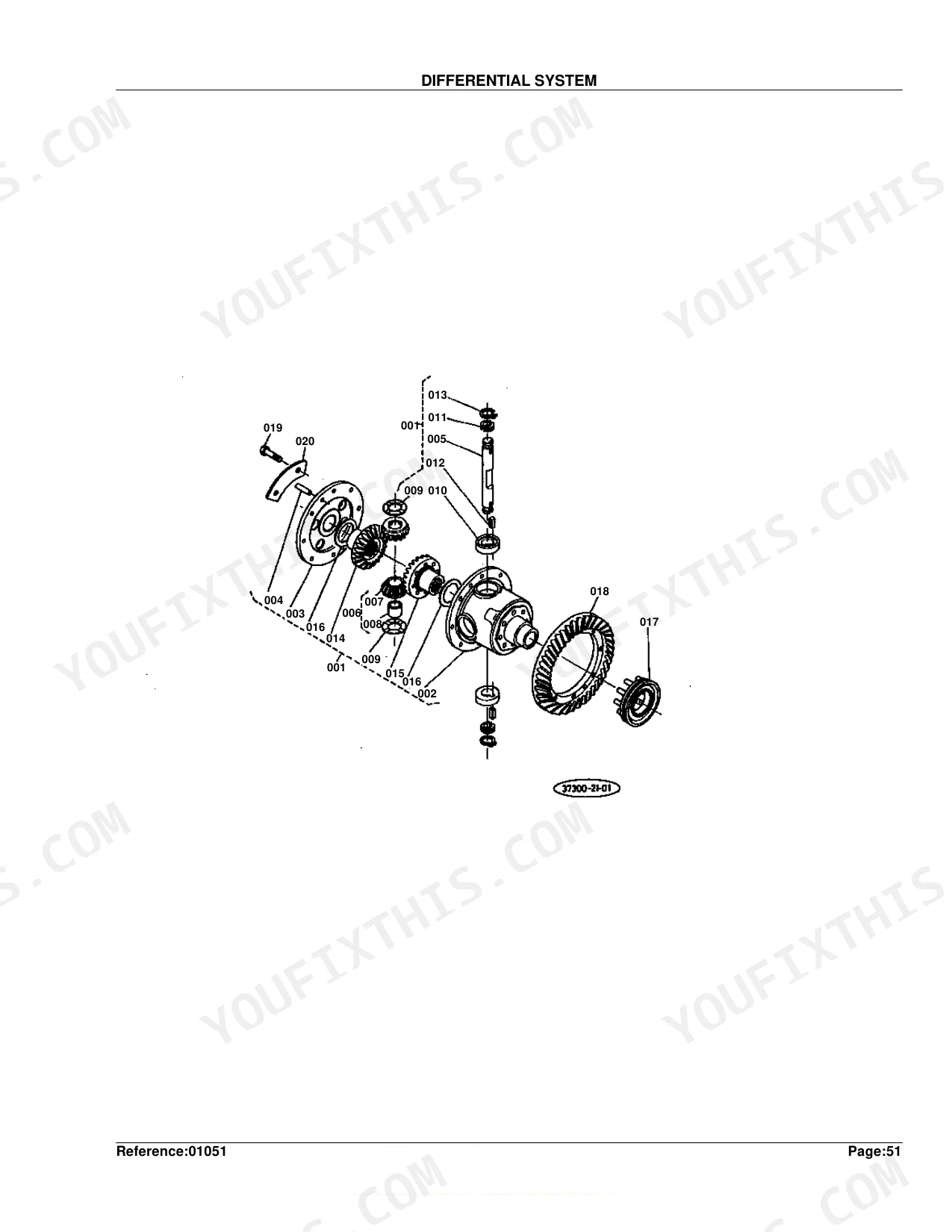
| Rear Axle, Differential & Brakes | Spiral Bevel Pinion, Rear Axle, Axle Case, Brake, Brake Pedal | |
| Front Axle & Steering | Front Axle Support, Front Axle, Tie Rod, Front Axle Bracket, Propeller Shaft, Power Steering, Integral Type Power Steering | |
| Hydraulics & 3-Point Hitch | Oil Hydraulic Pump, Oil Hydraulic Pump Section Parts, Oil Hydraulic Manifold, Oil Hydraulic System, Control Valve Section Parts, Relief Valve Section Parts, Oil Hydraulic Cylinder, Oil Hydraulic Cylinder Cover, Lift Arm, Oil Hydraulic Piping, 3-Point Link 1, 3-Point Link 2, Swing Drawbar, Control Valve, Control Valve Section Parts 1, Control Valve Section Parts 2 | |
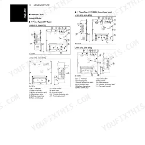
| Body & Operator Station | Step, Panel, Oil Tank, Seat, S.M.V.Emblem Bracket, Fender | |
| Decals & Accessories | Label | |
| Other Components | Differential System, Diff Lock Pedal, Diff Yoke Shaft, Regulator, Control Lever, Lever Guide, Front Diff Case, Bevel Gear Shaft, Center Pin, Drive Case, Drive Shaft, Balustrade |
Quick Reference Specifications
| Specification | Value | Page |
|---|---|---|
| Weight (kgf) for SWITCH,MAGNET | 1.29 kgf | p. 30 |
| Weight (kgf) for LINK,FUSIBLE | 0.005 kgf | p. 132 |
| Weight (kgf) for CORD,BATTERY | 0.25 kgf | p. 128 |
| Weight (kgf) for CORD,EARTH | 0.19 kgf | p. 128 |
| Weight (kgf) for LEVER,SHUTTLE | 0.57 kgf | p. 104 |
| Weight (kgf) for CABLE,PUSHPULL | 0.265 kgf | p. 104 |
| OIL PAN weight | 15.4 kgf | p. 8 |
Kubota L355SS Common Problems This Manual Covers
Engine shuts off unexpectedly
A machine that dies and will only click often has a fuel shutoff solenoid, relay, or wiring fault. This section shows the engine stop lever and its solenoid parts for inspection and replacement.
Manual Section: Engine Stop Lever p. 37No crank, only a click at the starter
A single click with no crank usually points to the starter solenoid or magnet switch, or a supply problem. This section identifies the starter section parts for testing and replacement.
Manual Section: Starter Section Parts p. 29Drives forward but will not reverse
When the L355SS moves forward but has no reverse, the shuttle-shift linkage or its parts are the common cause. This section shows the shuttle lever and its linkage components.
Manual Section: Shuttle Lever p. 103Intermittent starting or worn key switch
Erratic starting can trace to a worn key switch or its wiring. This section identifies the hour meter and switch parts so you can replace the switch and restore reliable starting.
Manual Section: Hour Meter and Switch p. 123Battery or cable connection faults
Corroded or loose battery cables leave the tractor slow to crank or dead. This section shows the battery and its cables for inspection and replacement.
Manual Section: Battery p. 127Hard starting from fuel starvation
Air or debris in the fuel supply leaves the diesel hard to start and rough. This section identifies the fuel filter and its section parts for cleaning the system and replacing the element.
Manual Section: Fuel Filter p. 133Frequently Asked Questions
Which tractor does this catalog cover?
It is the Kubota L355SS parts catalog, covering the L355SS tractor. It identifies parts across the engine, drivetrain, hydraulics, and electrical system with exploded diagrams and part numbers.
Does it include the wiring diagram?
Yes. The catalog includes the L355SS wiring diagram section, which shows the electrical layout for tracing circuits and identifying electrical parts. p. 131
Does it cover the transmission and shuttle-shift parts?
Yes. The catalog details the transmission case, main and counter shafts, and the shuttle lever linkage, so you can identify drivetrain and shuttle-shift components. p. 83
Are the hydraulic and three-point hitch parts listed?
Yes. The oil hydraulic system, control valve, cylinder, and lift arm sections are included with reference numbers and Kubota part numbers for the lift and hitch components. p. 137
What format is this manual in?
Immediate download of the complete 225-page searchable Parts Catalog. Open it on any device, whether that's a laptop at your desk or a phone out in the field.
Are there any print restrictions on this manual?
Yes. The PDF carries no DRM restrictions, so print any page or section you need for your shop. It works with any standard printer.
Are there hydraulic schematics in this Kubota L355SS manual?
Included. The Oil Hydraulic System section provides exploded views and part numbers for all components, but does not include circuit diagrams or specifications.

Reviews
There are no reviews yet.