


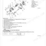
Finding the correct OEM part number shouldn't mean a wasted trip to the dealer. This Kubota L4610DT-HST catalog runs 342 pages of exploded views paired with numbered parts lists, covering every major assembly: engine internals, the HST transmission, front axle, hydraulic system, and cab hardware. Numbers are cross-referenced for both old-type and new-type variants, with separate breakdowns for the HST unit, governor, brake assembly, and hydraulic outlet block. Factory weights sit beside each listing, so you can plan shipping before you order: crankcase assembly at 49 kgf, flywheel at 29.8 kgf, cylinder head at 19.1 kgf. A wrong part on the bench is money out of your pocket. Everything is bookmarked by system and keyword-searchable, so your phone or tablet lands on the right assembly the moment you need it.
What's Inside This Kubota L4610DT-HST Parts Manual
| System | Pages | Key Topics |
|---|---|---|
| Crankcase | 6-7 | Comp.Crankcase, Plug, Cap Sealing, Pin Straight, Assy Pump Oil, Gear Oil Pump Drive |
| Oil Pan | 8-9 | Gasket Oil Pan, Plug Drain, Filter Oil, Guide Oil Gauge, Gauge Oil |
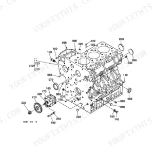
| Cylinder Head | 10-11 | Comp.Cylinder Head, Gasket Cylinder Head, Cap Sealing, Guide Inlet Valve, Seat Inlet Valve, Bolt Cylinder Head |
| Gear Case | 12-13 | Assy Case Gear, Gasket Gear Case, Support Oil Filter, Joint Pipe, Cartridge Oil Filter, Plug Oil Filler |
| Head Cover | 14-15 | Cover Cyl.Head, Gasket Head Cover, Plate B/Ther Element, Joint Breather, Plug Oil Filler, Pipe Breather |
| Main Bearing Case | 16-18 | Components, Part Number Reference |
| Camshaft and Idle Gear Shaft | 19-20 | Assy Camshaft, Gear Camshaft, Stopper Camshaft, Comp.Gear Idle, Shaft Idle Gear, Push Rod |
| Piston and Crankshaft | 21-22 | Piston, Assy Piston Ring, Pin Piston, Assy Connecting Rod, Metal Crankpin, Comp.Crankshaft |
| Flywheel [Hst Type] | 23-24 | Comp.Flywheel, Gear Ring, Bolt Flywheel, Comp.Housing F-W, Plug, Washer Spring |
| Fuel Camshaft | 25-26 | Assy Camshaft Fuel, Gear Injection Pump, Sleeve Governor, Case Governor Ball, Stopper Fuel C/Shaft |
| Engine Stop Lever | 27-28 | Apparatus Idling, Assy Lever Eng.Stop, Shaft Lever, Spring Return, Gasket Pump Cover, Support Solenoid |
| Injection Pump | 29-30 | Assy Pump Injection, Shim Injection Pump, Assy Cock Jet Start, Assy Pump Fuel, Gasket Fuel Pump, Assy Pipe Fuel |
| Injection Pump [Component Parts] | 31-32 | Plunger Pump, Valve Delivery., Holder Deliv.Valve, Assy Tappet, Rack Control, Sleeve Control |
| Governor | 33-35 | Components, Part Number Reference |
| Speed Control Plate | 36-37 | Assy Bolt Adjustment, Lever Speed Control, Plate Speed Control, Gasket, Stud, Washer Spring |
| Nozzle Holder and Glow Plug | 38-39 | Kit Holder Nozzle, Pipe Injection, Glow Plug, Cord Glow Plug, Assy Pipe Over Flow, Clip Pipe |
| Nozzle Holder [Component Parts] | 40-41 | Washer Adjusting, Spring Nozzle, Push Rod, Nut Nozzle, Piece Nozzle, Seal Heat |
| Water Flange and Thermostat [Rops Type] | 42-43 | Comp.Flange Water, Pipe Water Return, Gasket Water Flange, Cover Thermostat, Gasket Thermostat, Assy Thermostat |
| Water Pump | 44-46 | Components, Part Number Reference |
| Valve and Rocker Arm | 47-49 | Components, Part Number Reference |
| Inlet Manifold [Rops Type] | 50-52 | Components, Part Number Reference |
| Upper Gasket Kit | 53-54 | Kit Gasket Upper, O Ring, Gasket Cylinder Head, Seal Valve Stem, Gasket Ex-Manifold, Gasket Thermostat |
| Lower Gasket Kit | 55-57 | Components, Part Number Reference |
| Exhaust Manifold/Muffler | 58-60 | Components, Part Number Reference |
| Air Cleaner [Rops Type] | 61-62 | Assy Cleaner Air(W), Comp.Body A/C, Assy Element Inner, Assy Element Outer, Assy Cover A/C, Hose |
| Stop Solenoid/Engine Stop Wire | 63-64 | Solenoid Stop, Assy Lever Eng.Stop, Shaft Lever, Lever Engine Stop, Gasket Pump Cover, Support Solenoid |
| Accelerator Lever [Hst Type] [Rops Type] | 65-66 | Grip, Shaft Accel.Control, Support Accel.Lever, Spring Accel.Lever, Rod Connecting, Lever Accel.Link |
| Accelerator Rod [Hst Type] | 67-68 | Assy Rod Accel., Nut, Washer Plain, Pin Split, Cushion |
| Fuel Tank [Rops Type] | 69-71 | Components, Part Number Reference |
| Fuel Pipe and Fuel Filter | 72-74 | Components, Part Number Reference |
| Fuel Filter [Component Parts] | 75-76 | Assy Filter Fuel, Assy Body, Handle Filter, Gasket, Element Filter, Spring |
| Fan | 77-78 | Pulley Fan, Bolt Flange, V Belt A, Flange Fan |
| Water Pipe [Rops Type] | 79-80 | Hose, Band, Hose Drain, Band Pipe, Band Cord |
| Radiator | 81-82 | Assy Radiator, Shroud Fan, Cap Radiator, Plug Drain, O Ring, Bolt Flange |
| Reserve Tank [Rops Type] | 83-84 | Tank Reserve, Cap, Gasket, Pipe Water Over Flow, Clip Pipe, Stay Reserve Tank |
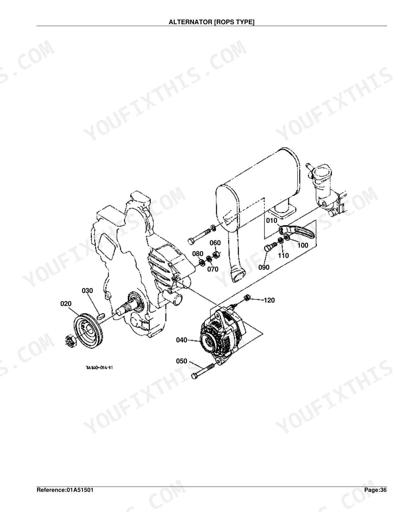
| Alternator [Rops Type] | 85-87 | Components, Part Number Reference |
| Alternator [Component Parts] [Rops Type] | 88-89 | Assy Alternator, Pulley Alternator, Rotor, Bearing Ball, Assy Rectifier, Assy Regulator |
| Starter | 90-91 | Assy Starter, Stud, Nut, Bolt, Washer Spring |
| Starter [Component Parts] | 92-93 | Assy Starter, Assy Yoke, Assy Armature, Clutch Over Running, Assy Switch Magnetic, Assy Holder Brush |
| Battery [Rops Type] | 94-95 | Label Battery, Cap Battery, Cord Battery, Band Cord, Retainer Battery |
| Switch 1 [Hst Type] [Rops Type] | 96-97 | Timer Key Stop, Controller, Relay Glow, Relay Starter, Switch Main, Switch Safety |
| Switch 2 [Hst Type] [Rops Type] | 98-100 | Components, Part Number Reference |
| Panel Board | 101-102 | Assy Panel, Assy Cable Flexible, Plate Panel, Seal Panel, Bolt Set, Screw |
| Panel Board [Component Parts] | 103-104 | Assy Panel, Hood Panel, Assy Tachometer, Assy Meter Fuel, Assy Thermometer, Case |
| Light 1 [Rops Type] [Old Type] | 105-106 | Assy Light Head, Bulb, Assy Wire Harness, Unit Lamp, Grille Light Rh, Lens Hazard Light |
| Light 1 [Rops Type] [New Type] | 107-108 | Assy Light Head, Bulb, Assy Wire Harness, Unit Lamp, Grille Light Rh, Assy Light Combi.Rh |
| Electrical Wiring [Hst Type] [Rops Type] | 109-111 | Components, Part Number Reference |
| Clutch | 112-113 | Assy Plate Pressure, Pin Straight, Bolt, Comp.Disk Clutch |
| Clutch Lever | 114-115 | Lever Clutch, Case Propeller Shaft, Holder Clutch, Bearing Release, Fork Clutch Release, Key Fork |
| Clutch Pedal [Hst Type] [Rops Type] | 116-117 | Comp.Pedal Clutch, Bush, Seal Oil, Spring, Cover Pedal, Rod Clutch |
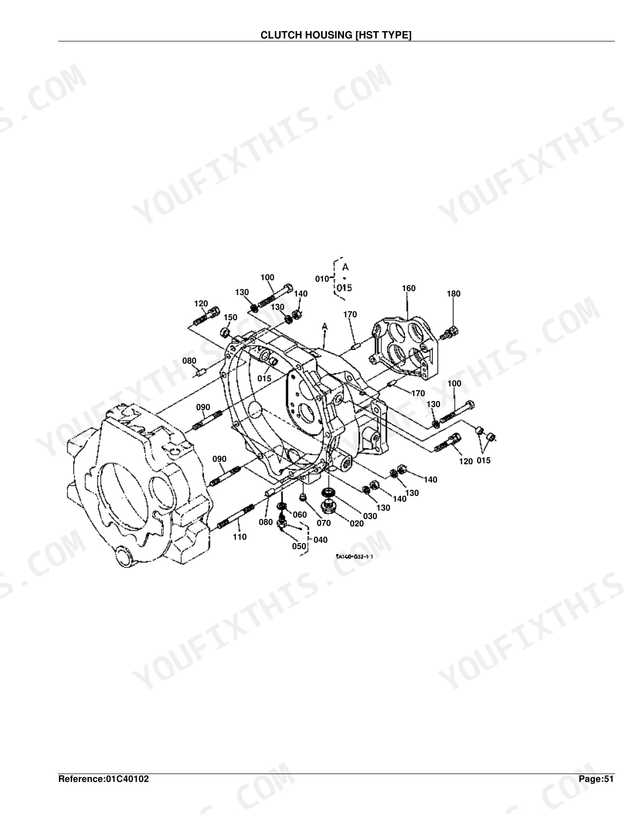
| Clutch Housing [Hst Type] | 118-119 | Assy Housing Clutch, Bush, Plug Drain, Washer with Rubber, Pin Split, Holder Bearing |
| Mid Case [Hst Type] | 120-121 | Case Mid HST, Holder Bearing, Pin Straight, Holder Mid-Brg.Pto, Gasket Mid Case, Assy HST |
| HST [Component Parts] [Hst Type] | 122-125 | Components, Part Number Reference |
| Transmission Case [Hst Type] | 126-127 | Case Transmission, Gauge Oil, Pin Straight, Stud, Holder Bearing, Plug |
| Main Shaft [Hst Type] | 128-129 | Gear-Shaft PTO, Bearing Ball, Seal Oil, Gear PTO |
| Input Shaft [Hst Type] | 130-131 | Gear-Shaft, Cir Clip External, Gear, Bearing Ball |
| Output Shaft [Hst Type] | 132-133 | Gear-Shaft HST, Coupling, Pin Spring, Bearing Ball |
| Spiral Bevel Pinion [Hst Type] | 134-135 | Gear-Shaft, Coupling, Bearing Ball, Collar Thrust, Shim, Gear |
| Rear Differential | 136-137 | Assy Differential, Case Differential, Shaft Diff.Pinion, Pinion Diff., Washer Side Gear, Shim Differential |
| PTO Clutch [Hst Type] | 138-139 | Countershaft PTO, Bearing Ball, Gear PTO, Cam Clutch, Spring, Holder Bearing |
| PTO Shaft [Hst Type] | 140-141 | Gear, Collar Thrust, Bearing Needle, Shaft PTO Drive, Bearing Ball, Coupling PTO |
| Range Gear Shift Fork [Hst Type] | 142-143 | Fork Range Shift, Rod Shiff, Arm Range Shift, Stopper, Ball, Pin Spring |
| Differential Lock Shift Fork [Hst Type][Rops Type] | 144-146 | Components, Part Number Reference |
| Rear Axle [Rops Type] | 147-148 | Shaft Diff.Gear, Bearing Ball, Axle Rear, Spacer, Gear, Case Rear Axle |
| Brake | 149-151 | Components, Part Number Reference |
| Brake Rod 1 [Hst Type] [Rops Type] | 152-153 | Assy Lever Brake, Shaft Brake, Assy Rod Brake, Rod Brake Lower, Rod Clutch Brake, Pin Joint |
| Brake Rod 2 [Hst Type] | 154-155 | Rod Brake Lh, Rod Brake Rh, Pin Joint, Washer Plain, Pin Split |
| Cruise Control Lever [Hst Type] | 156-157 | Rod, Ball Link, Lever HST Link, Shaft, Assy Lever, Bracket |
| Cruise Control Cable [Hst Type] | 158-159 | Wire Control, Pin Snap, Lever, Grip Lever, Wire PTO, Grommet |
| Neutral Holder Link [Hst Type] | 160-161 | Bracket HST, Assy Arm, Arm Holder, Shaft Holder, Damper HST, Rod |
| Speed Control Pedal [Hst Type] [Rops Type] | 162-163 | Rod, Assy Pedal, Cover HST Pedal, Assy Bracket Pedal, Pin HST Pedal, Bolt Flange |
| Range Gear Shift Lever [Hst Type] [Rops Type] | 164-165 | Assy Arm, Lever Range Shift, Assy Holder Range, Grip Lever, Shaft Fulcrum, Guide HST Cahnge |
| Range Gear Shift Rod [Hst Type] | 166-167 | Lever Range Shift, Pin Spring, Rod Range, Turnbuckle, Pin Snap |
| PTO Gear Shift Lever [Hst Type] | 168-169 | Arm PTO Shift, Lever PTO, Stopper, Stay Wire, Wire PTO, Grip PTO Lever |
| Front Wheel Drive Lever | 170-171 | Lever Shift, O Ring, Stopper, Lever 4Wd Change, Pin Spring, Grip Lever |
| Brake Pedal [Hst Type] [Rops Type] | 172-173 | Shaft Pedal, Support Pedal Shaft, Assy Pedal Brake Rh, Bearing Needle, Comp.Lock Parking, Assy Link |
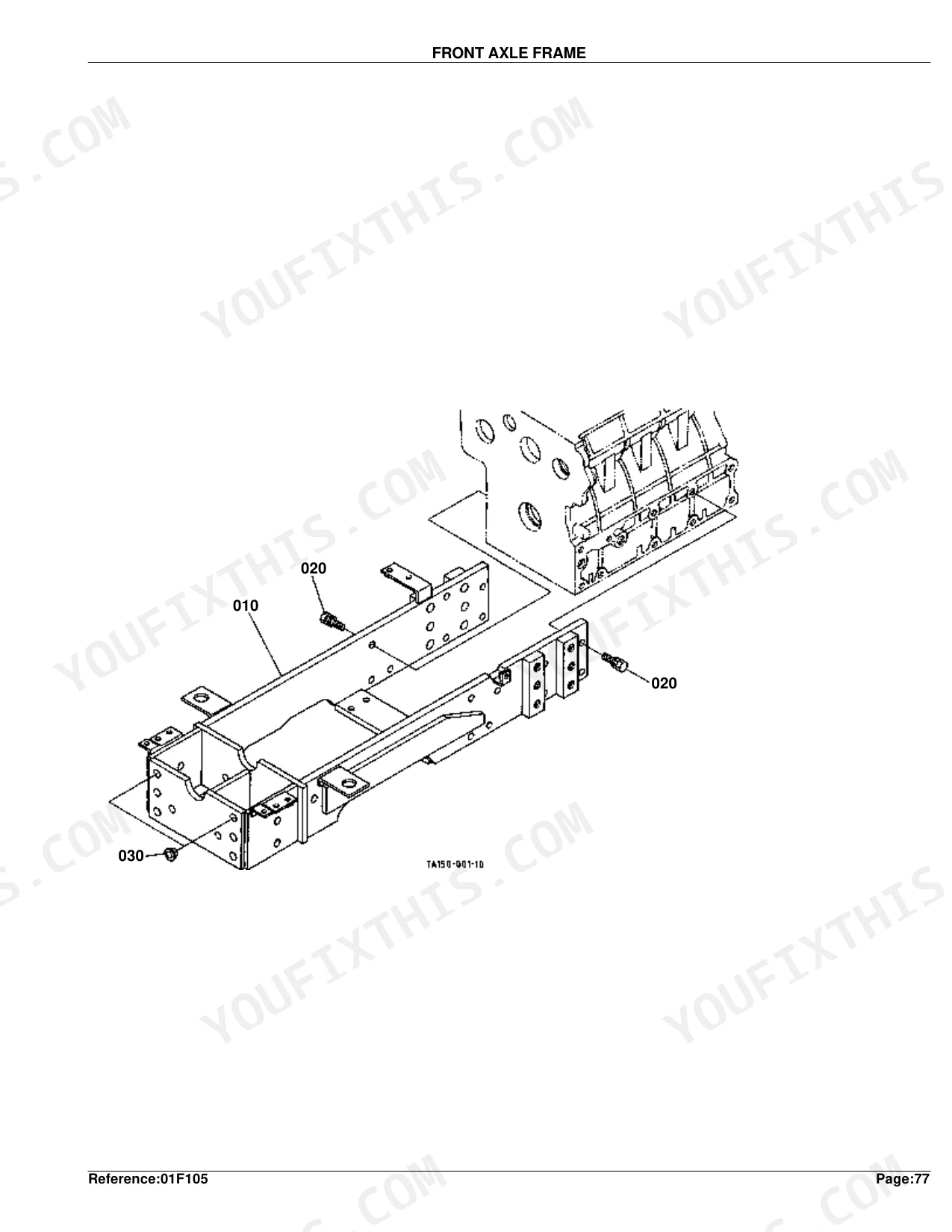
| Front Axle Frame | 174-175 | Comp.Frame F-Axle, Bolt, Plug |
| Propeller Shaft | 176-178 | Components, Part Number Reference |
| Front Wheel Drive Shaft | 179-180 | Shaft Drive, Bearing Ball, Spring, Ball, Gear 4Wd Shift |
| Front Differential Case | 181-182 | Case Front Axle, Assy Holder Front, Bush, Nipple Grease, Collar Thrust, Assy Holder Rear |
| Bevel Gear (Front) | 183-184 | Assy Gear Bevel, Bearing Taper-Roller, Collar, Pin Straight, Shim, Cir Clip Internal |
| Differential(Front) | 185-186 | Case Diff., Pin Straight, Bearing Ball, Cir Clip External, Shaft Pinion, Shim |
| Front Axle Case | 187-188 | Assy Support Case, Seal Oil, Nipple Grease, Case Front Gear, Bearing Ball, Shaft Bevel Gear |
| Differential Gear Shaft | 189-190 | Shaft Yoke, Case Bevel Gear, Pin Straight, O Ring, Bearing Ball, Shim |
| Front Axle | 191-192 | Axle Front, Bearing Ball, Shim, Gear Bevel, Collar, Seal Oil |
| Steering Handle [Hst Type] [Rops Type] | 193-194 | Assy Post Steering, Bearing Ball, Shaft Steering, Coupling Steering, Assy Wheel Steering, Pad Steering |
| Steering Controller | 195-197 | Components, Part Number Reference |
| Steering Cylinder | 198-199 | Cylinder Hydraulic, Assy Rod Tie, Joint Tie Rod, Cover Dust, Ring Set, Nut |
| Steering Cylinder [Component Parts] | 200-201 | Cylinder Hydraulic, Kit Head Hyd.Cyl., Kit Seal, O Ring, Seal, U-Ring |
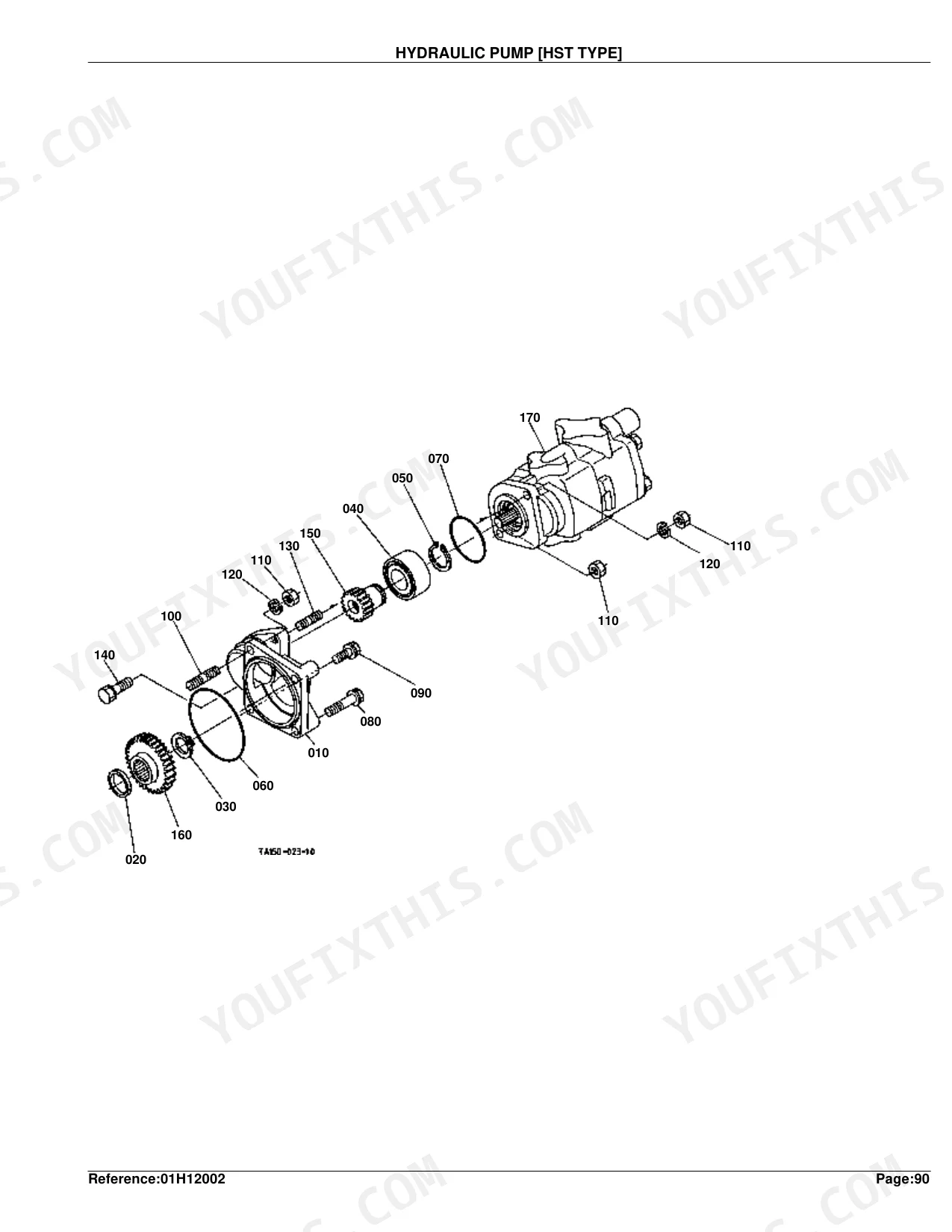
| Hydraulic Pump [Hst Type] | 202-203 | Holder Pump, Collar, Cir Clip External, Bearing Ball, Stud, Gear |
| Hydraulic Pump [Component Parts] [Hst Type] | 204-205 | Assy Pump Hydraulic, Comp.Gear Hyd.Pump, Square Ring, Coupling, Pin Straight, O Ring |
| Hydraulic Oil Line(Inlet) [Hst Type] | 206-207 | Bracket Filter, Cartridge Oil Filter, Pipe Inlet HST, O Ring, Hose Inlet, Band Pipe |
| Hydraulic Oil Line(Delivery) [Hst Type] | 208-209 | Comp.Pipe Delivery, O Ring, Bolt, Joint, Gasket |
| Hydraulic Oil Line(Ps) [Hst Type] | 210-211 | Hose Delivery, Joint, Gasket, Hose Aux.Cont.Valve, Adapter Cylinder, Assy Hose Return |
| Hydraulic Outlet Block [Hst Type] | 212-214 | Components, Part Number Reference |
| Hydraulic Pipe [Hst Type] | 215-216 | Pipe Suction HST, O Ring, Filter, Bolt Joint, Adapter, Filter Oil |
| Oil Cooler [Hst Type] | 217-218 | Cooler Oil, Comp.Pipe Oil Cooler, Tube, Joint, O Ring, Hose Oil Cooler |
| Hydraulic Cylinder | 219-221 | Components, Part Number Reference |
| Lift Arm | 222-223 | Piston Hyd., Rod Hyd., Pin Spring, Arm Lift, Link Control, Pin Lift Rod |
| Feed Back Lever | 224-226 | Components, Part Number Reference |
| Control Valve | 227-229 | Components, Part Number Reference |
| Control Valve [Component Parts] [Old Type] | 230-231 | Assy Valve Control, Spring Spool, Holder Spring, Plug, Poppet, O Ring |
| Control Valve [Component Parts] [New Type] | 232-233 | Assy Valve Control, Spring Spool, Holder Spring, Plug, Poppet, O Ring |
| Position Control Lever [Rops Type] | 234-236 | Components, Part Number Reference |
| Top Link | 237-238 | Assy Link Top, Link Top, Nipple Grease, Joint Top Link, Nut Top Link, Pin Joint |
| 3-Point Linkage 1(Lower Link) [Old Type] | 239-241 | Components, Part Number Reference |
| 3-Point Linkage 1 (Lower Link) [New Type] | 242-243 | Comp.Link Lower Lh, Assy Stabilizer, Comp.Stab.Front, Comp.Joint, Pin Stabilizer Rear, Nut Lock |
| 3-Point Linkage 2(Lift Rod) | 244-245 | Assy Rod, Rod Lift Lower, Joint Gear Case, Pin Lift Rod, Pin Spring, Ring Snap |
| Drawbar | 246-248 | Components, Part Number Reference |
| PTO Protector [Rops Type] | 249-250 | Kit Cover PTO (A), Stay, Bolt, Washer Plain, Spring Plate, Label PTO Warning |
| Front Grille | 251-252 | Grille Front, Cushion, Cover Front, Grille Radiator, Nut Flange, Spacer |
| Front Grille Support [Hst Type] [Rops Type] | 253-255 | Components, Part Number Reference |
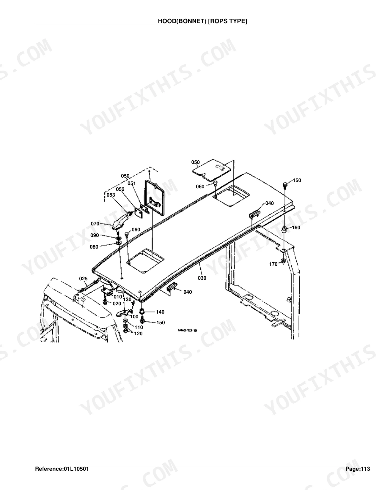
| Hood(Bonnet) [Rops Type] | 256-257 | Comp.Bonnet, Cushion, Cover Bonnet, Spring Bonnet Cover, Handle Mascot, Lock Front Grille |
| Hood(Bonnet) Side Rh | 258-259 | Holder, Grip Handle, Hook Bonnet, Shield Side Cover, Glille Rh, Plate Washer |
| Hood(Bonnet) Side Lh | 260-261 | Holder, Grip Handle, Hook Bonnet, Shield Side Cover, Glille Lh, Plate Washer |
| Side Cover Lower [Rops Type] | 262-263 | Cover Rh, Kit Cover Lh(A), Kit Cover Lh(B), Bolt Flange, Rubber Block, Label Start Caution |
| Shutter Plate [Rops Type] | 264-266 | Components, Part Number Reference |
| Panel Frame [Hst Type] [Rops Type] | 267-268 | Bonnet, Nut Spring, Cover Panel Under, Assy Frame Panel, Bearing Needle, Seal Oil |
| Fender [Hst Type] [Rops Type] | 269-271 | Components, Part Number Reference |
| Floor Seat [Hst Type] [Rops Type] | 272-273 | Kit Floor Seat(A), Bolt Flange, Cover Tools Box, Spring Cord Straight, Cushion, Cover Floor Seat |
| Seat [Rops Type] | 274-275 | Assy Seat, Cushion Seat, Back Seat, Hinge, Knob, Assy Suspension |
| Seat Suspension [Component Parts] | 276-277 | Assy Suspension, Frame Suspension, Shaft, Spring Suspension, Knob Adjust, Cushion |
| Step [Hst Type] [Rops Type] | 278-279 | Cushion, Washer, Bolt, Aid Lh, Mat |
| ROPS [Rops Type] [Old Type] | 280-281 | Assy ROPS, Comp.Frame Lh, Comp.Frame Rh, Bolt, Washer Spring, Hex.Bolt |
| ROPS [Rops Type] [New Type] | 282-283 | Kit ROPS Replacement, Comp.Frame Lh, Comp.Frame Rh, Bolt, Washer Spring, Nut |
| Smv Emblem | 284-285 | Smv Sign Kit, Sign Smv, Socket Smv Sign, Bolt Square Neck, Nut, Spade Smv Sign |
| Front Wheel (8.3-16) | 286-287 | Assy Tire, Assy Tire Lh, Wheel, Tire, Stud, Nut |
| Front Wheel (10-16.5) | 288-289 | Assy Front Wheel, Assy Front Wheel Rh, Tire, Wheel, Stud, Nut |
| Front Wheel (27*8.5-15) | 290-291 | Assy Front Wheel, Tire, Wheel, Label Tire, Stud, Nut |
| Front Wheel (29*12.50-15) | 292-293 | Assy Tire, Tire Assy, Tire, Wheel, Stud, Nut |
| Rear Wheel (13.6-24) | 294-296 | Components, Part Number Reference |
| Rear Wheel (14.9-24) | 297-299 | Components, Part Number Reference |
| Rear Wheel (17.5-24) | 300-302 | Components, Part Number Reference |
| Rear Wheel (41*14.00-20) | 303-305 | Components, Part Number Reference |
| Rear Wheel (21.5L-16.1) | 306-308 | Components, Part Number Reference |
| Label 1 [Hst Type] [Rops Type] | 309-310 | Label Front Grille, Label Battery, Label Start Caution, Label Key Stop, Label Fan Belt, Label Muffler |
| Label 2 [Hst Type] [Rops Type] | 311-312 | Mark Position, Label ROPS Warning, Label Drawbar, Label Safety, Label PTO Warning, Label Parking |
| Accessories and Service Parts | 313 | Manual Instruction, Statement Warranty, Assy Key Main Switch, Bolt, Nut, Stud |
| Air Cleaner Cover Kit [Option] | 314-315 | Kit Cover Air Cleane, Cover Air Cleaner, Bolt Flange, Washer Plain, Manual Instruction |
| Position Control Lever (With Draft) [Option] | 316-318 | Components, Part Number Reference |
| Draft Control Lever (With Draft) [Option] | 319-320 | Shaft Draft, Spring Plate, Lever Cam, Lever Draft, Grip Lever, Tube Lever |
| Top Link Holder (With Draft) [Option] | 321-323 | Components, Part Number Reference |
| Swinging Drawbar/Clevis Drawbar [Option] | 324-326 | Components, Part Number Reference |
| Remote Control Valve Lever 1 [Rops Type] [Option] | 327-328 | Assy Valve Aux.Con., Cover Aux.Con.Valve, Assy Pipe Cont.Valve, Lever Aux.Con.Valve, Grip Lever, Stay Aux.Cont.Valve |
| Remote Control Valve Lever 2 [Rops Type] [Option] | 329-330 | Assy Valve Aux.Con., Cover Aux.Con.Valve, Assy Pipe Cont.Valve, Lever Aux.Con.Valve, Grip Lever, Stay Aux.Cont.Valve |
| Remote Control Valve Lever 3 [Rops Type] [Option] | 331-332 | Assy Valve Aux.Con., Cover Aux.Con.Valve, Assy Pipe Cont.Valve, Lever Aux.Con.Valve, Grip Lever, Stay Aux.Cont.Valve |
| Remote Control Valve Coupler 1 [Option] | 333-334 | Adapter, Hose Aux.Cont.Valve, Assy Coupler Female, Plug Coupler, Support Coupler, Assy Coupler Male |
| Remote Control Valve Coupler 2 [Option] | 335-336 | Adapter, O Ring, Hose Aux.Cont.Valve, Assy Coupler Female, Plug Coupler, Support Coupler |
| Remote Control Valve Coupler 3 [Option] | 337-338 | Adapter, O Ring, Hose Aux.Cont.Valve, Assy Coupler Female, Plug Coupler, Support Coupler |
| ROPS [Rops Type] [Option] [Old Type] | 339-340 | Assy ROPS, Comp.Frame Lh, Comp.Frame Rh, Bolt, Washer Spring, Label ROPS Warning |
| ROPS [Rops Type] [Option] [New Type] | 341-342 | Kit ROPS Replacement, Comp.Frame Lh, Comp.Frame Rh, Bolt, Washer Spring, Label ROPS Warning |
Quick Reference Specifications
| Specification | Value | Page |
|---|---|---|
| COMP.CRANKCASE Weight | 49 kgf | p. 7 |
| OIL PAN Weight | 4.1 kgf | p. 9 |
| COMP.CYLINDER HEAD Weight | 19.1 kgf | p. 11 |
| ASSY CASE GEAR Weight | 4.2 kgf | p. 13 |
| COMP.FLYWHEEL Weight | 29.8 kgf | p. 24 |
| ASSY PUMP INJECTION Weight | 2.5 kgf | p. 30 |
| ASSY RADIATOR Weight | 4.1 kgf | p. 82 |
| ASSY STARTER Weight | 3.65 kgf | p. 91 |
| CASE MID HST Weight | 34 kgf | p. 121 |
| ASSY DIFFERENTIAL Weight | 6.2 kgf | p. 137 |
| AXLE REAR Weight | 11 kgf | p. 148 |
| ASSY SEAT Weight | 9.6 kgf | p. 275 |
Kubota L4610DT-HST Common Problems This Manual Covers
Hydrostatic drive loses movement and creeps weakly when you push the forward pedal p. 120
Check the exploded view on page 120 to pin down the hydrostatic transmission components, then match the filter part numbers to your serial number. Swapping the whole mid case means handling 34 kgf, so factor that into shipping.
Manual Section: Mid Case [Hst Type]Oil leakage spotted around the engine block base and front gear case p. 6
Inspect the engine diagram on page 6 for the right plug and cap sealing identifiers, and cross-reference the wear pins and gaskets against your serial range. The full crankcase assembly runs 49 kgf, so budget for the freight.
Manual Section: CrankcaseFront axle engagement grinds and fails to lock into four wheel drive mode p. 174
Review the chassis diagram on page 174 to locate the front axle frame components, then match the engagement linkage and bearing numbers to your cab variant. A complete rear axle assembly, by contrast, weighs 11 kgf.
Manual Section: Front Axle FrameOperator seat cushion is torn and the suspension base bottoms out over rough terrain p. 274
Confirm the seat component part numbers on page 274 before you order, and check the applicability notes so the hinge and suspension assemblies fit your ROPS variant. The complete seat assembly weighs 9.6 kgf.
Manual Section: Seat [Rops Type]Frequently Asked Questions
What transmission does the Kubota L4610DT-HST use?
The L4610DT-HST runs a Hydrostatic Transmission, which the model name itself makes clear. The parts book backs this up with dedicated sections such as "HST [COMPONENT PARTS] [HST TYPE]" on page 122.
How do I find Kubota L4610 parts by serial number?
Start with the "S.No." column in the parts list. When an entry shows ">=", your equipment's serial number needs to be greater than or equal to the number listed. When it shows "<=", your serial number should fall at or below the number shown.
What are the replacement specifications for hydrostatic transmission filters?
Two filters appear in the book. The "CARTRIDGE OIL FILTER" (Part No. T0070-37710) sits in the "HYDRAULIC OIL LINE(INLET) [HST TYPE]" section on page 207 at 0.725 kgf (1.595 lb). A "FILTER OIL" (Part No. TA240-59900) shows up in the "OIL COOLER [HST TYPE]" section on page 218 at 0.955 kgf (2.101 lb). Replacement procedures and torque specs, though, aren't included in this parts manual.
What are the replacement specifications for seals and gaskets?
For seals and gaskets, the book gives part numbers and weights. One example: the "GASKET CYLINDER HEAD" (Part No. 19077-03310) at 0.13 kgf (0.286 lb) on page 54. What it doesn't include is replacement procedures or torque specs for those parts.
How quickly can I access this Kubota L4610DT-HST manual after buying?
The 342-page searchable PDF downloads the moment checkout clears. Open it on a laptop, tablet, or phone and take it straight to the shop floor.
Are there any print restrictions on this Kubota L4610DT-HST manual?
Yes. Print as many copies as you like; there are no restrictions. Plenty of mechanics run off only the section they need for the job at hand.
Document Quality
This document is a scanned PDF with an optical character recognition (OCR) layer, allowing you to search and copy text throughout the entire file. The text quality is crisp and easy to read on all pages. Diagrams and illustrations are clear raster images, and their labels and part numbers are generally readable, though some fine details may show pixelation when heavily zoomed. The pages are clean, free from scan artifacts, stains, or skewed content. There are no notable blank or filler pages.


Reviews
There are no reviews yet.