


Need factory-level service data for your Kubota LA402, or any loader across the eight-model LA271–LA402 range? This 62-page front loader workshop manual runs from hydraulic circuit to final reassembly. It maps both the 3-position and 4-position bucket control valve circuits, with 20 pages on the hydraulic system alone: boom cylinders, relief valve, and fluid routing. There are torque tables split between general fasteners and hydraulic fittings, exploded-view diagrams, a troubleshooting chart, and 30 pages of step-by-step procedures for control valve teardown, cylinder rebuild, and loader dismounting. Seat the boom and bucket cylinder piston mounting nut to 170–183 N-m (125–135 ft-lbs); the connecting bar bolt calls for 147 N-m (108 ft-lbs) across the line. Stop digging through forum threads for the right number. Open it on any device and the section bookmarks drop you straight on the spec.
What's Inside This Kubota LA271–LA402 Series Manual
| System | Pages | Key Topics |
|---|---|---|
| Safety Instructions | 4-7 | - |
| Terminology | 8 | Front Loader Overview, Bucket Cylinder, Boom, Hydraulic Control Valve, Side Frame, Mounting Pin, Main Frame, Bucket |
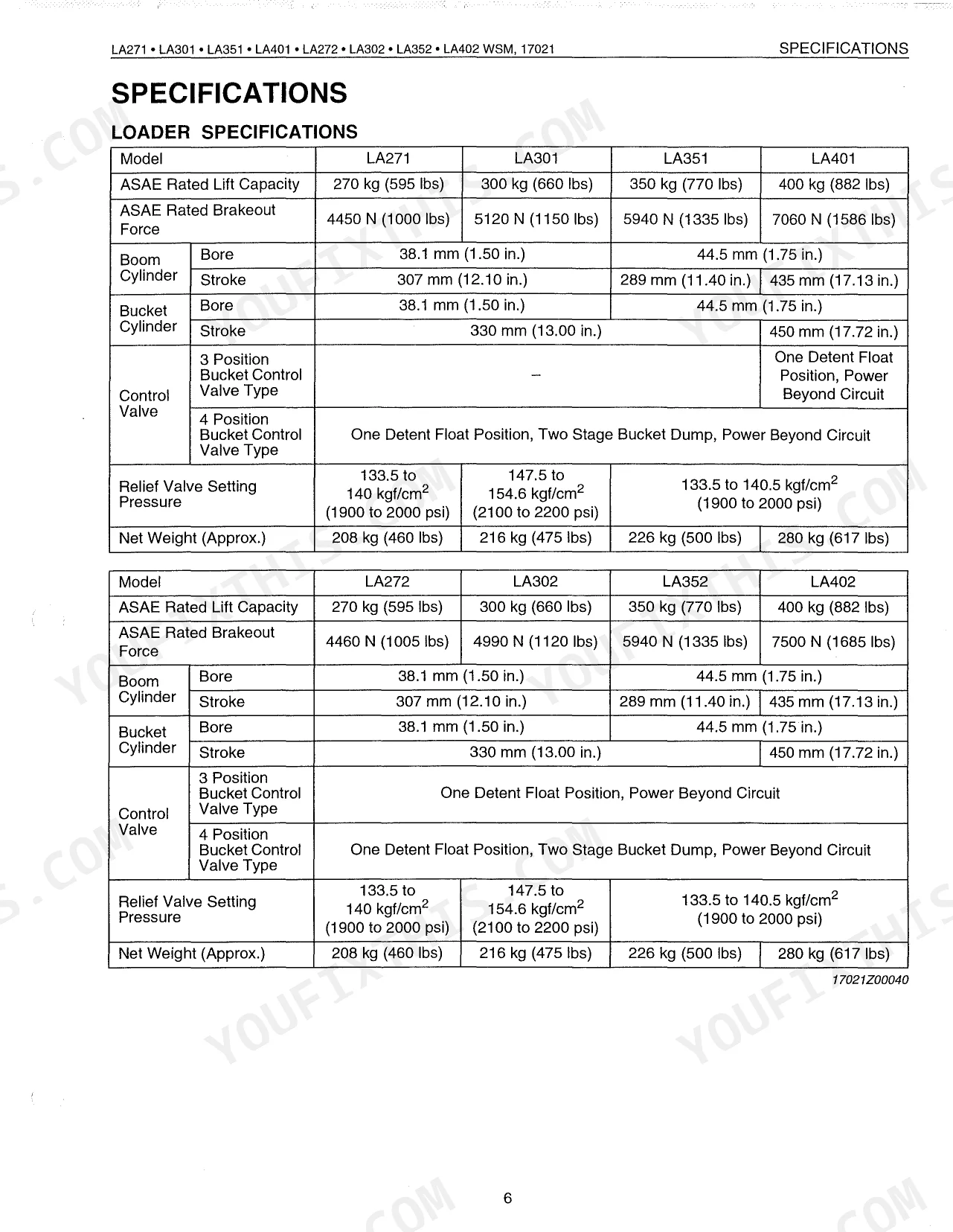
| Specifications | 9-12 | Loader Specifications, Bucket Specifications, Operating Dimensions, Performance Ratings (No Load) |
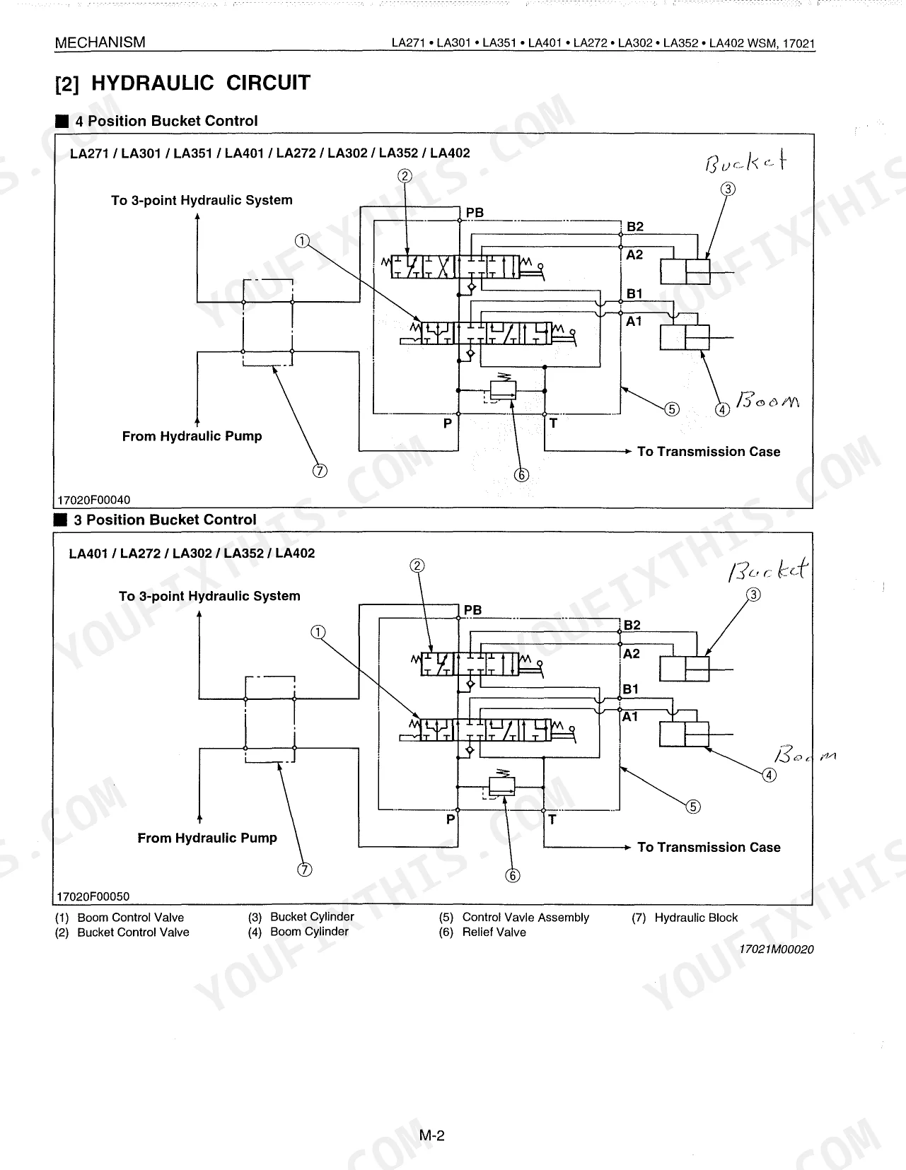
| Mechanism | 13-40 | Features, Hydraulic Circuit, Control Valve Assembly (La271 La301 La351, La271 La301 La351 and La401 La272 La302 La352 La402, La401 La272 La302 La352 La402), Relief Valve |
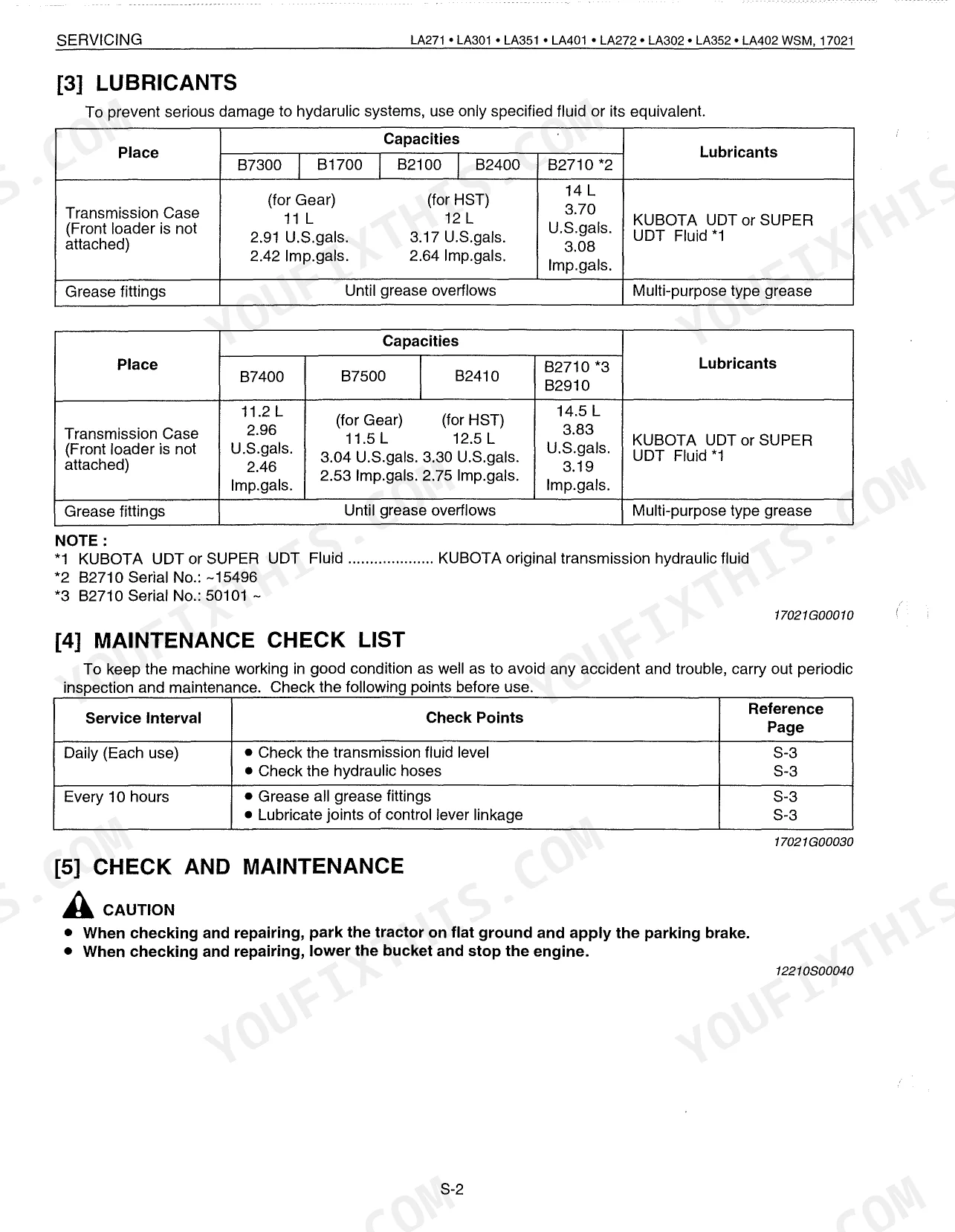
| Servicing | 41-62 | General (Identification, Lubricants, Maintenance Check List, Check And Maintenance, Check Points Of Each Use Or Daily, Check Points Of Every 10 Hours), Troubleshooting |
Quick Reference Specifications
| Specification | Value | Page |
|---|---|---|
| LA271, LA301, LA351, LA272, LA302, LA352 | ||
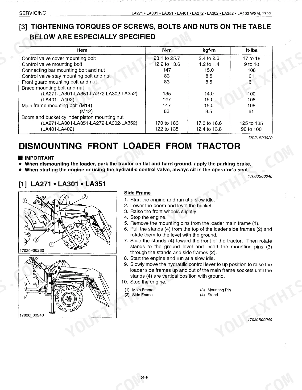
| Boom and bucket cylinder piston mounting nut | 170 to 183 N-m (125 to 135 ft-lbs) | p. 48 |
| Brace mounting bolt and nut | 135 N-m (100 ft-lbs) | p. 48 |
| All Models | ||
| Control valve cover mounting bolt | 23.1 to 25.7 N-m (17 to 19 ft-lbs) | p. 48 |
| Control valve mounting bolt | 12.2 to 13.6 N-m (9 to 10 ft-lbs) | p. 48 |
| Connecting bar mounting bolt and nut | 147 N-m (108 ft-lbs) | p. 48 |
| Control valve stay mounting bolt and nut | 83 N-m (61 ft-lbs) | p. 48 |
| Front guard mounting bolt and nut | 83 N-m (61 ft-lbs) | p. 48 |
| Main frame mounting bolt (M14) | 147 N-m (108 ft-lbs) | p. 48 |
| LA401, LA402 | ||
| Boom and bucket cylinder piston mounting nut | 122 to 135 N-m (90 to 100 ft-lbs) | p. 48 |
| Brace mounting bolt and nut | 147 N-m (108 ft-lbs) | p. 48 |
| LA271, LA272, LA351, LA352, LA401, LA402 | ||
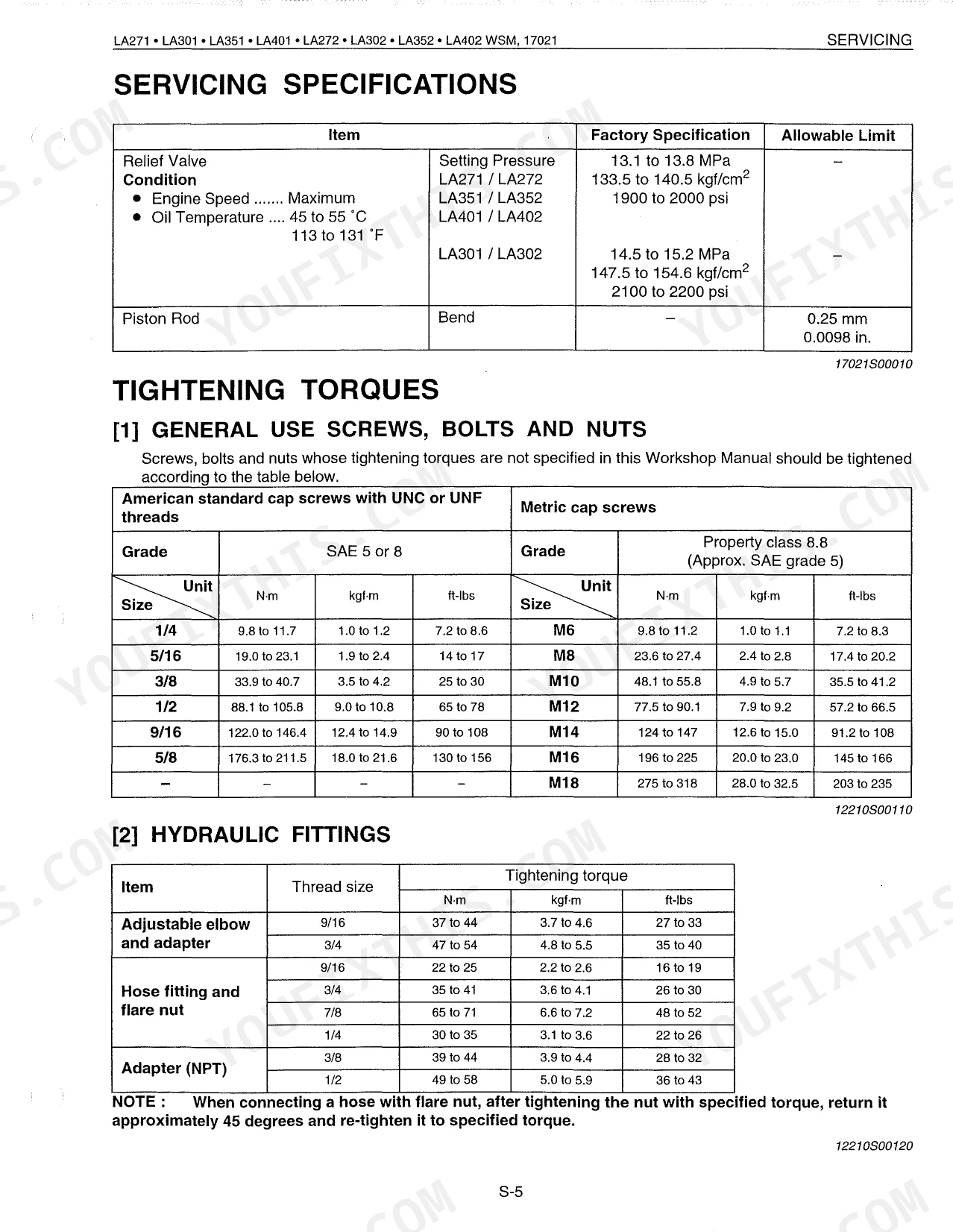
| Relief Valve Setting Pressure (High Flow Models) | 13.1 to 13.8 MPa | p. 47 |
| LA301, LA302 | ||
| Relief Valve Setting Pressure (Standard Flow Models) | 14.5 to 15.2 MPa | p. 47 |
Kubota LA271–LA402 Series Common Problems This Manual Covers
Kubota LA271 front end loader drops by its weight when parked with the engine turned off. p. 46
Inspect the boom cylinder tube and piston ring for excessive wear as outlined on page 46. Measure the piston rod straightness and replace if the bend exceeds the 0.25 mm allowable limit shown on page 47. Check the control valve for internal leakage.
Manual Section: ServicingLoader boom lifts extremely slowly or feels weak when picking up a heavy bucket load. p. 46
Test the relief valve and inspect the boom cylinder tube for internal bypassing. Check the Troubleshooting Procedures on page 46 for hydraulic circuit faults. If replacing the control valve, torque the cover mounting bolts to 23.1 to 25.7 N-m as specified on page 48.
Manual Section: ServicingVisible hydraulic oil leaks from hose connections and cylinder tube joints during normal bucket operation. p. 47
Pinpoint the source by checking all hydraulic lines and tube joints for damage. Tighten 9/16 thread adjustable elbow fittings to 37 to 44 N-m and 7/8 thread hose fittings to 65 to 71 N-m. See page 47 for torque specifications and replace any cracked hoses without delay.
Manual Section: ServicingExcessive play and rattling noise where the loader main frame attaches to the tractor mounts. p. 48
Examine the main frame mounting hardware and pins for severe wear. Torque the M14 main frame mounting bolts to 147 N-m and the M12 bolts to 83 N-m. Refer to page 48 for the full fastener tightening procedures to eliminate bracket movement.
Manual Section: ServicingFrequently Asked Questions
What are the torque specs for Kubota LA271/LA301/LA351/LA401/LA272/LA302/LA352/LA402 mounting bolts and hydraulic fittings?
Page 47 lists torques for unspecified screws, bolts, and nuts in two tables: American standard cap screws (UNC or UNF threads) and Metric cap screws. An M6 metric cap screw, for example, takes 9.8 to 11.2 N-m (1.0 to 1.1 kgf-m, 7.2 to 8.3 ft-lbs). Hydraulic fittings carry their own values; a 9/16 adjustable elbow and adapter needs 37 to 44 N-m (3.7 to 4.6 kgf-m, 27 to 33 ft-lbs). Certain mounting bolts are called out separately, such as the control valve cover mounting bolt at 23.1 to 25.7 N-m (17 to 19 ft-lbs).
What do error codes or warning signs mean on a Kubota LA271/LA301/LA351/LA401/LA272/LA302/LA352/LA402 loader?
This loader uses safety alert symbols rather than error codes. DANGER marks an imminently hazardous situation that, if not avoided, will result in death or serious injury. WARNING marks a potentially hazardous situation that, if not avoided, could result in death or serious injury. CAUTION marks a potentially hazardous situation that, if not avoided, may result in minor or moderate injury. The manual lists no specific error codes for the loader.
How do I remove or reinstall a Kubota LA271/LA301/LA351/LA401/LA272/LA302/LA352/LA402 front loader?
Start by parking the tractor on flat ground, applying the parking brake, then lowering the boom and leveling the bucket. On LA271/LA301/LA351 models, remove the main frame mounting pins, rotate the stands to ground level, and work the hydraulic control lever to lift the side frames out of the main frame sockets. On LA401/LA272/LA302/LA352/LA402 models, raise the boom to rotate the stands, pull the snap pins, slide the stands to the setting position, dump the bucket about 20 degrees, then lower the boom to lift the front wheels slightly. Last, disconnect the four hydraulic hoses with quick couplers from the control valve and back the tractor away. Reassembly reverses these steps; torque all bolts to spec (see page 47-48).
What are the replacement specifications for Cylinder seals?
Replacing the piston seal (2) and O-ring (3) on the piston (1) calls for both a slide jig and a correcting jig, as shown on page 56. The slide jig is sized by model: dimension C is 37.46 mm (1.475 in.) for LA271/LA301/LA272/LA302 and 43.8 mm (1.724 in.) for LA351/LA401/LA352/LA402. Place the slide jig on the piston, fit the O-ring, then slide the piston seal over it, and compress the seal to size by pressing the piston into the correcting jig. Do not turn or roll the piston seal as you install it.
Is this Kubota LA271–LA402 Series Workshop Manual a digital download?
Immediate download of the full 62-page searchable workshop manual. Open it on any device: laptop at your desk or phone in the field.
Am I able to print pages from this Kubota LA271–LA402 Series manual?
Absolutely. No DRM or copy protection. Print the whole manual or just the pages you need. Any home or office printer works.
Does this Kubota LA271–LA402 Series manual include hydraulic schematics?
Full hydraulic system diagrams are included, covering circuits, valve locations, and hydraulic component specs for the Kubota LA271–LA402 Series.
Document Quality
This document is a scanned copy of a physical workshop manual. An OCR layer has been applied, so you can search and copy the full text, which is crisp and easy to read. Diagrams and illustrations are raster images, but they are clear, and all labels are readable. Pages are generally clean, though faint circular marks from binder holes are visible on the margins throughout the document, indicating its scanned origin. Several blank pages are present, consistent with the layout of a physical manual.


Reviews
There are no reviews yet.