
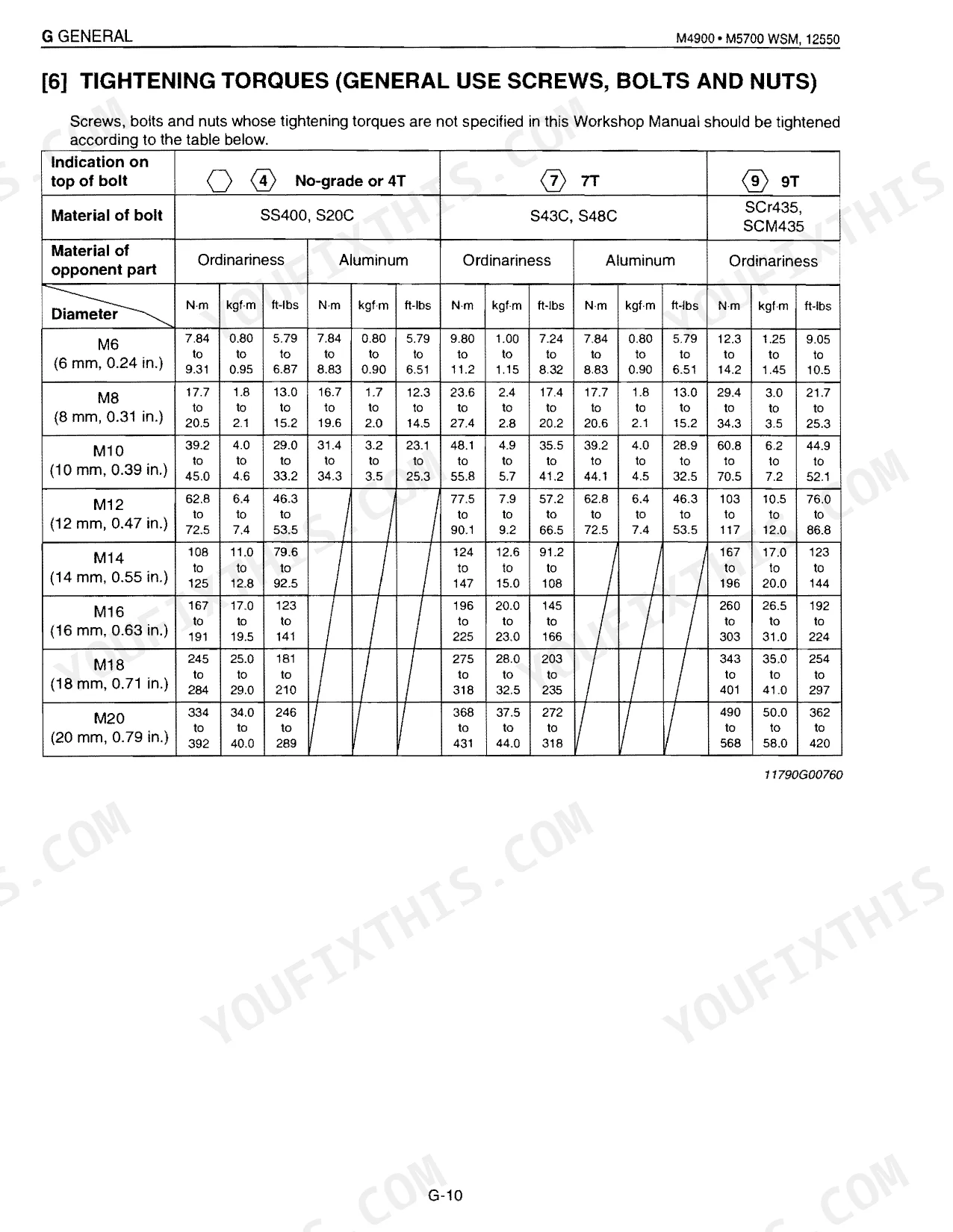


Need factory torque values for your M4900 or M5700? This 741-page Kubota M4900 service manual PDF (OEM M4900 • M5700 WSM, #12550) pulls the M4900SU, M5700HD, M6800HD, M5700DT-N, and M5700 Hydraulic Shuttle into one factory-written volume. Wiring diagrams cover both ROPS and CABIN harness layouts; hydraulic schematics trace the three-point lift circuit and power steering. There are 22 pages of torque tables, 59 pages of hydraulic procedures, and maintenance intervals running from daily checks through 3,000-hour service points. Another 16 pages of troubleshooting charts walk the engine, shuttle clutch, brakes, and axles. Front wheel mounting nuts torque to 166.7 to 196.1 N·m, rear nuts to 260 to 304 N·m, both straight from the spec tables. With the tractor down, download a bookmarked file you can search by keyword and open on any device right in the shop.
What's Inside This Kubota M4900–M6800 Series Manual
| System | Pages | Key Topics |
|---|---|---|
| General | 14-71 | Features, Tractor Identification, Handling Precautions for Electrical Parts and Wiring (Battery, Fuse, Connector, Handling of Circuit Tester), Lubricants, Fuel and Coolant |
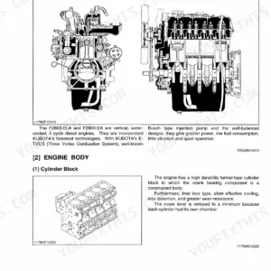
| Sect 1 Engine | 72-151 | Features, Engine Body (Cylinder Block, Cylinder Head, Crankshaft, Piston and Piston Rings, Connecting Rod, Camshaft, Fuel Camshaft, Rocker Arm, Intake and Exhaust Valve, Flywheel) |
| Sect 2 Clutch | 152-187 | Travelling Clutch, Features, Travelling Clutch Linkage, Operation, Clutch Engaged, Clutch Disengaged, Pto Clutch, Structure |
| Sect 3 Transmission | 188-237 | Structure (Shuttle Shift Section, Main Gear Shift Section, Hi-Lo, Creep Shift Section, Four Wheel Drive Section), PTO System, Differential Gear (Structure, Operation) |
| Sect 4 Rear Axle | 238-249 | Features, Final Reduction System, Internal Gear to Planetary Gear Backlash, Planetary Gear Thrust Collar Thickness, Planetary Gear Shaft O.D., Planetary Gear I.D., Needle O.D., Changing Transmission Fluid |
| Sect 5 Brakes | 250-265 | Features, Features of Wet Disc Brakes, Fade, Operation, During braking, Brake Pedal Free Play, Brake Pedal Shaft O.D., Brake Pedal Bushing I.D. |
| Sect 6 Front Axle | 266-293 | Structure, 2 Wheel Drive Type, 4 Wheel Drive Type, Front Wheel Alignment, Camber, Kingpin Angle, Caster, Toe-in |
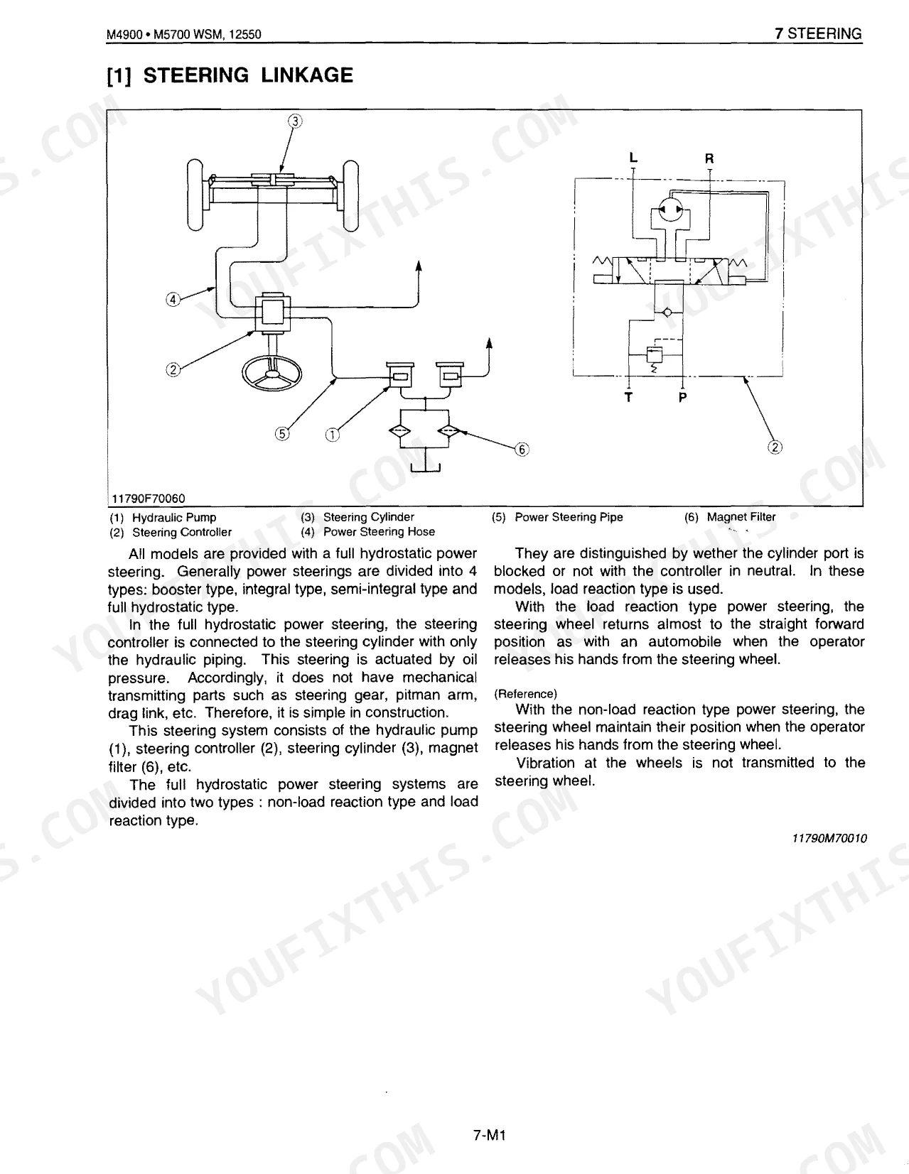
| Sect 7 Steering | 294-320 | Steering Linkage, Power Steering Hydraulic Circuit, Power Steering System Hydraulic Pump, Steering Controller (Control Valve, Metering Device, Oil Flow), Steering Cylinder |
| Sect 8 Hydraulic | 321-362 | Three Point Hydraulic System, Hydraulic Circuit for Three Point Hydraulic System, Hydraulic Pump, Oil Filter, Position Control Valve, Relief Valve, Hydraulic Cylinder |
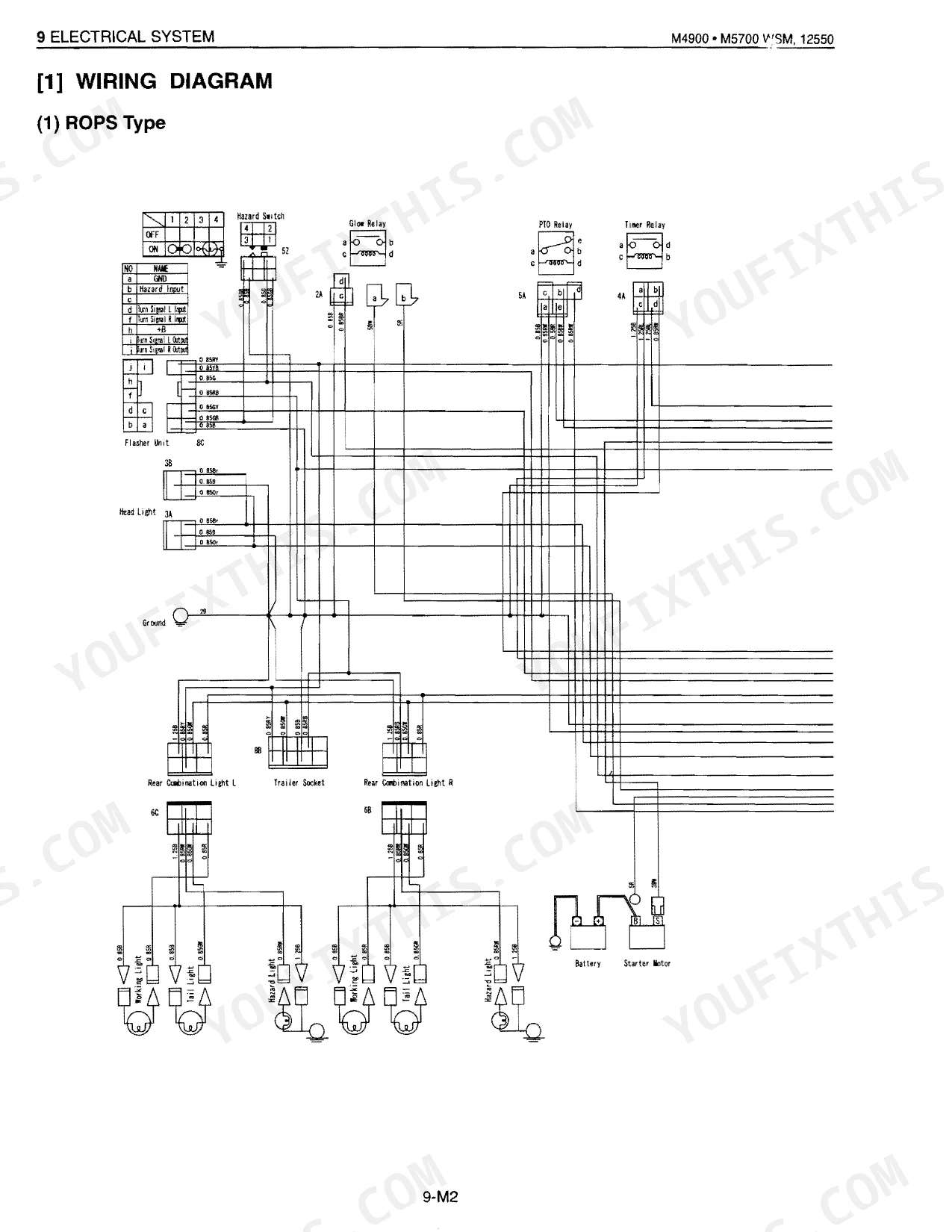
| Sect 9 Electrical | 363-440 | Wiring Diagram (ROPS Type, CABIN Type, Body Harness, CABIN Harness) |
| Sect 10 Cab | 441-510 | Air Conditioner System, Principles of Air Conditioner, Expansion and Evaporation, Condensing Gaseous, Refrigeration Cycle, Outline of Aie Conditioning System, Refrigeration System, Compressor |
| Supplement M4900Su | 511-553 | Safety Instructions, Specifications, Dimensions, G. General (Features, Tractor Identification), Clutch (Servicing), Transmission (Mechanism, Servicing) |
| Supplement M5700Hd | 554-617 | Safety Decals, Specifications, G. General (Features), Maintenance, Check and Maintenance, Special Tool, Clutch (Servicing, Checking and Adjusting), Transmission (Mechanism) |
| Supplement M5700 Hyd Shuttle Trans | 618-700 | Safety Instructions, Specifications, G. General (Features, Maintenance, Check and Maintenance, Special Tool), Clutch (Servicing), Transmission (Mechanism, Servicing) |
| Supplement M5700Dt-N | 701-741 | Safety Instructions, Specifications, Dimensions, G. General (Features, Lubricants, Fuel and Coolant, Tires, Wheel Hub), Engine (Servicing), Clutch (Servicing) |
Quick Reference Specifications
| Specification | Value | Page |
|---|---|---|
| M5700 Hydraulic Shuttle | ||
| Hydraulic shuttle warning reset procedure | Not found. The manual provides troubleshooting for 'Shuttle Clutch Slip' which may indicate a problem, but no explicit 'reset' procedure for a warning light. | p. 585 |
| Shuttle Clutch Slip probable causes | Operating pressure is low, Shuttle Valve malfunctioning, Clutch disc or drive plate excessively worn, Shuttle clutch pack damaged | p. 585 |
| Shuttle Clutch Slip solution | Adjust, Repair or replace, Replace | p. 585 |
| M6800HD | ||
| Cylinder head screw torque | Not found for M6800HD. The main manual lists torque for F2803 engine (M4900/M5700 models), but M6800HD uses a V3300-E engine and specific torque for its cylinder head bolts is not provided in the M5700HD/M6800HD supplement. | p. 103 |
| M4900, M5700 | ||
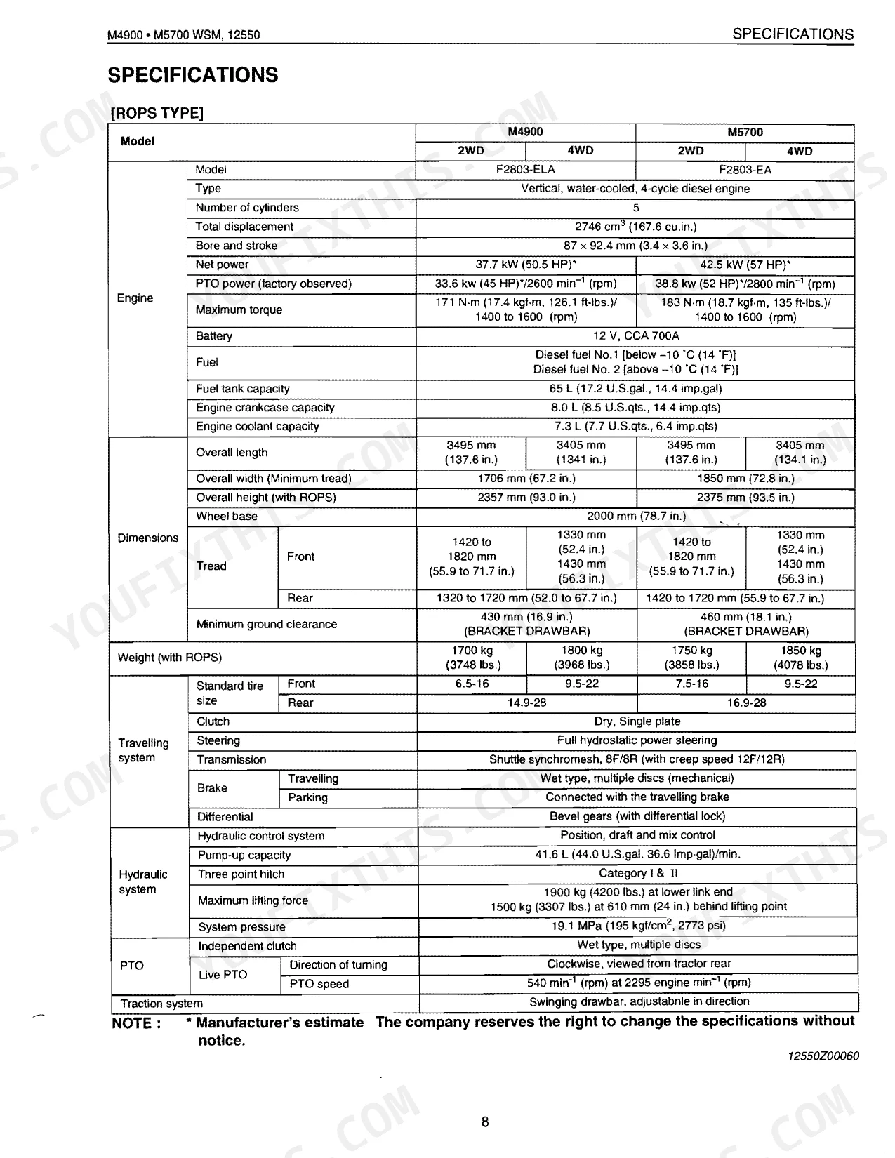
| Front wheel mounting nut torque | 166.7 to 196.1 N·m (17.0 to 20.0 kgf·m, 122.9 to 144.6 ft-lbs) | p. 31 |
| Rear wheel mounting nut torque | 260 to 304 N·m (26.5 to 31.0 kgf·m, 192 to 224 ft-lbs) | p. 31 |
| Hydraulic oil filter replacement interval | 300 hours | p. 26 |
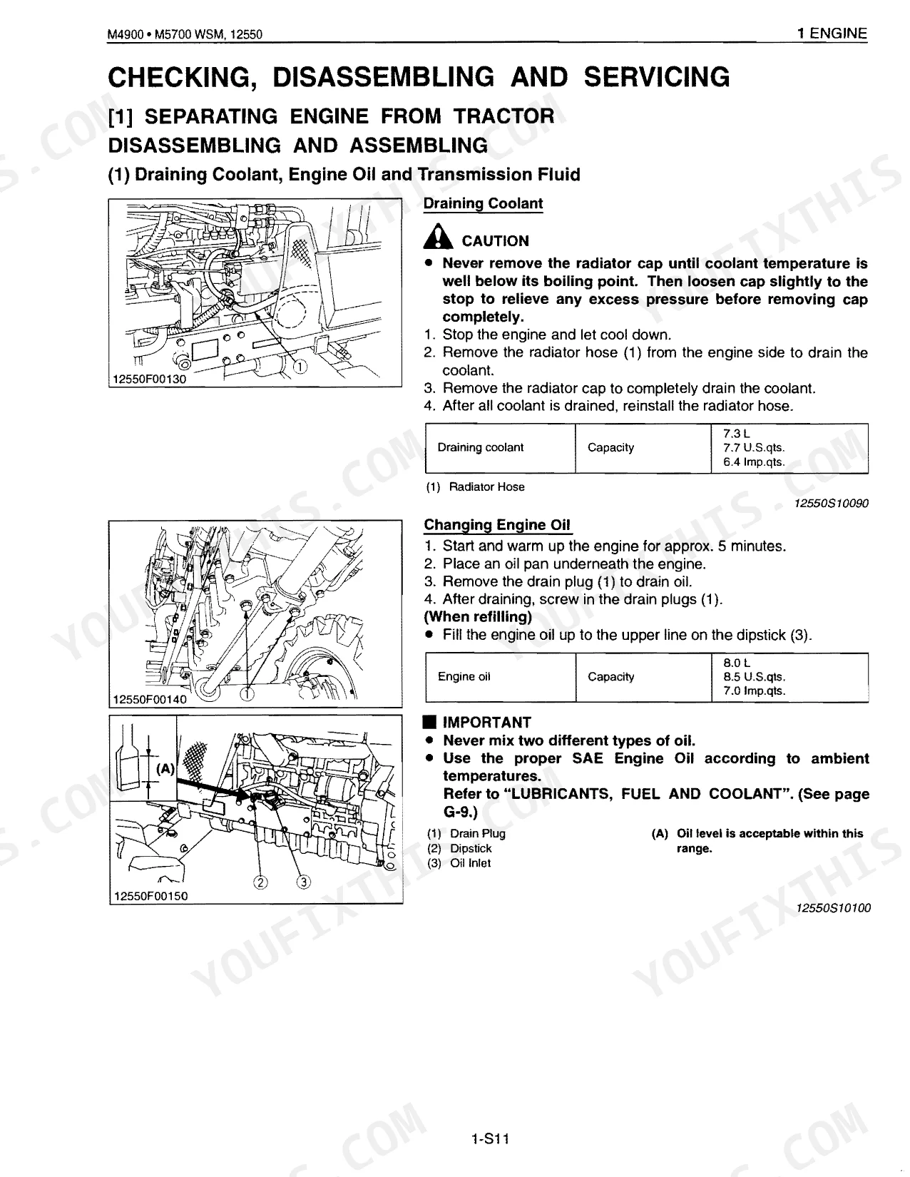
| Engine oil filter replacement interval (initial) | 50 hours | p. 26 |
| Engine oil filter replacement interval (regular) | 200 hours | p. 26 |
| Fuel filter element replacement interval | 400 hours | p. 26 |
| Clutch Pedal Free play | 35 to 45 mm (1.4 to 1.8 in.) | p. 166 |
| Clutch Pedal Total Stroke (ROPS) | 165 to 170 mm (6.5 to 6.7 in.) | p. 166 |
Kubota M4900–M6800 Series Common Problems This Manual Covers
Kubota M5700 implement not rising or lowering after changing the hydraulic fluid and filter
Inspect the hydraulic oil filter installation. Replace the filter every 300 hours, as noted on page 26. Verify the gasket seats fully so the system cannot draw air. Tighten the main delivery pipe retaining nut to 46.6 to 50.9 N·m (34.4 to 37.6 ft-lbs) for a complete seal.
Manual Section: Hydraulic System TroubleshootingShuttle shift lever feels excessively stiff or binds completely when shifting between forward and reverse
Check the shuttle shift linkage for binding and wear. Measure the shuttle shift rod and set its length to about 160 mm (6.3 in.), per page 205. On reassembly, torque the shuttle case assembly screw nuts to 23.5 to 27.4 N·m (17.4 to 20.3 ft-lbs).
Manual Section: Transmission TroubleshootingTravelling clutch slips under load, chatters during engagement, or exhibits severe vibration at high RPM
Measure the clutch pedal free play as shown on page 166 and adjust the linkage to hold 35 to 45 mm (1.4 to 1.8 in.) of clearance. Inspect the clutch disc for wear. Torque all clutch mounting screws to 23.5 to 27.5 N·m (17.4 to 20.3 ft-lbs).
Manual Section: Clutch Troubleshooting (Travelling Clutch)Engine idles rough, lacks power under heavy draft loads, or stalls completely in the field
Drain the fuel system and inspect the lines for restrictions. Replace the fuel filter element every 400 hours, per page 26. Confirm engine oil pressure at idle speed reads at least 98 kPa to rule out internal wear before the machine goes back to work.
Manual Section: Engine TroubleshootingFrequently Asked Questions
How to reset the Kubota M4900/M5700 fuel system after filter change?
After a filter change, bleed the fuel system with the fuel cock open. On CAB models, pump the fuel pump knob until you feel resistance, then start the engine at mid-speed (around 1500 min-1 rpm) and accelerate to clear the air. On ROPS models, open the fuel cock, start the engine, and let it run about 30 seconds before shutting down.
How to reset the Kubota M5700 hydraulic shuttle if it squeals or won’t engage?
When the M5700 hydraulic shuttle won't engage cleanly, measure the clearance between the internal snap ring and the pressure plate. On serial numbers M5700-53536 and below, factory spec is 1.8 to 2.0 mm (0.071 to 0.079 in.), with an allowable limit of 3.6 mm (0.142 in.). If clearance falls outside that limit, correct it by combining clutch discs.
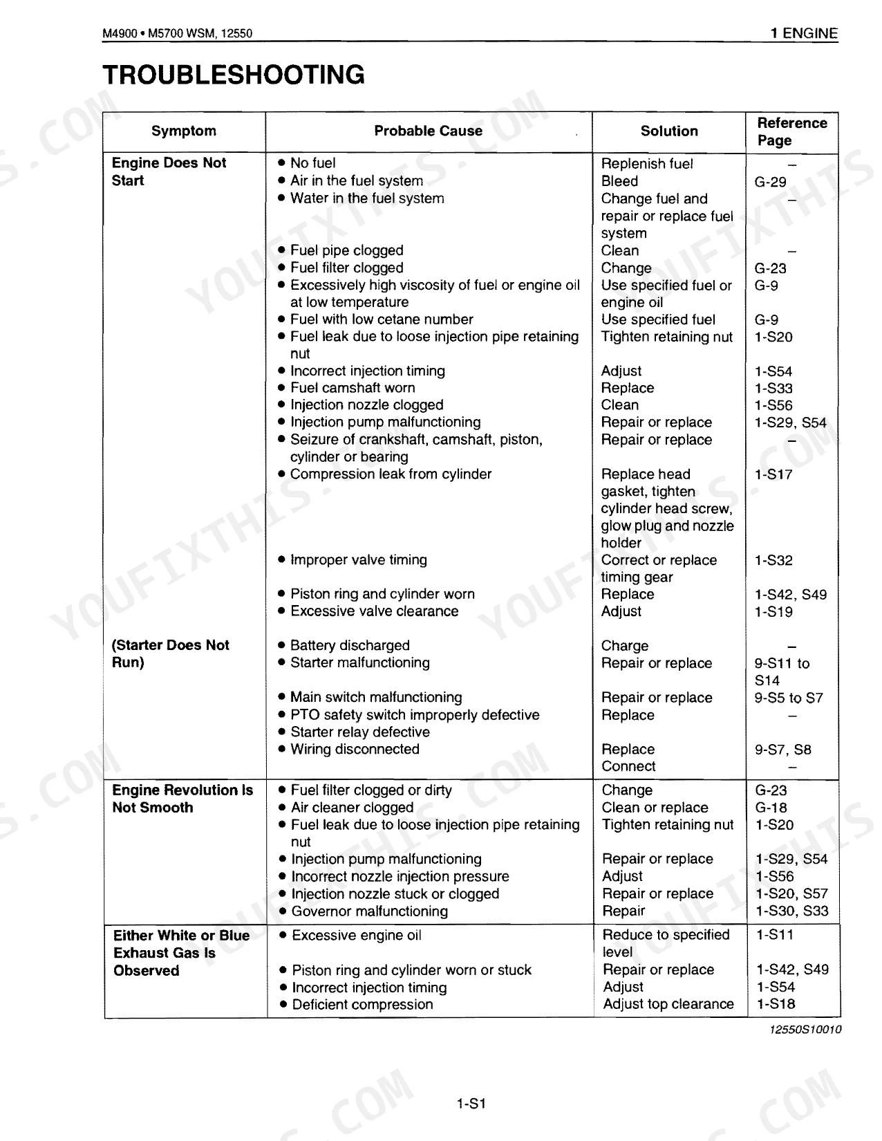
How to reset a Kubota M4900 no-start or hard-start condition?
A no-start or hard-start usually traces to fuel: replenish if empty (page G-29), bleed trapped air (page G-29), or change a clogged fuel filter (page G-23). A discharged battery needs recharging. Starter or main switch faults call for repair or replacement, detailed on pages 9-S11 to S14 and 9-S5 to S7 respectively.
How to reset Kubota warning lights or fault indicators on M-series tractors?
Warning lights and fault indicators reset only after you clear the root cause. Take the 'Fuel Limit and Charging Lamp' that stays on while the engine runs: it points to a short circuit between the alternator L terminal lead and chassis, or a failed alternator. Repair or replace as detailed on pages 9-M1 to M25 or 9-S15 to S20.
How quickly can I access this Kubota M4900–M6800 Series manual after buying?
Immediate download of the complete 741-page searchable Service Manual. Open it on any device: laptop at your desk, phone out in the field.
Is this Kubota M4900–M6800 Series Service Manual printable?
None at all. The PDF is DRM-free, so print whatever sections you need for the shop. Standard letter or A4 paper works.
Are electrical wiring diagrams included in this Kubota M4900–M6800 Series?
Complete wiring diagrams are included, covering all electrical circuits, harness routing, and connector pinouts for the Kubota M4900–M6800 Series.
Document Quality
This document is a scanned PDF with an OCR layer, allowing you to search and copy text throughout. The text quality is crisp and generally easy to read on all pages. Diagrams and illustrations are clear raster images, with labels consistently readable. The pages are clean, free from notable scan artifacts, stains, marks, or skewed content. There are a few blank pages scattered throughout the document.

Reviews
There are no reviews yet.