
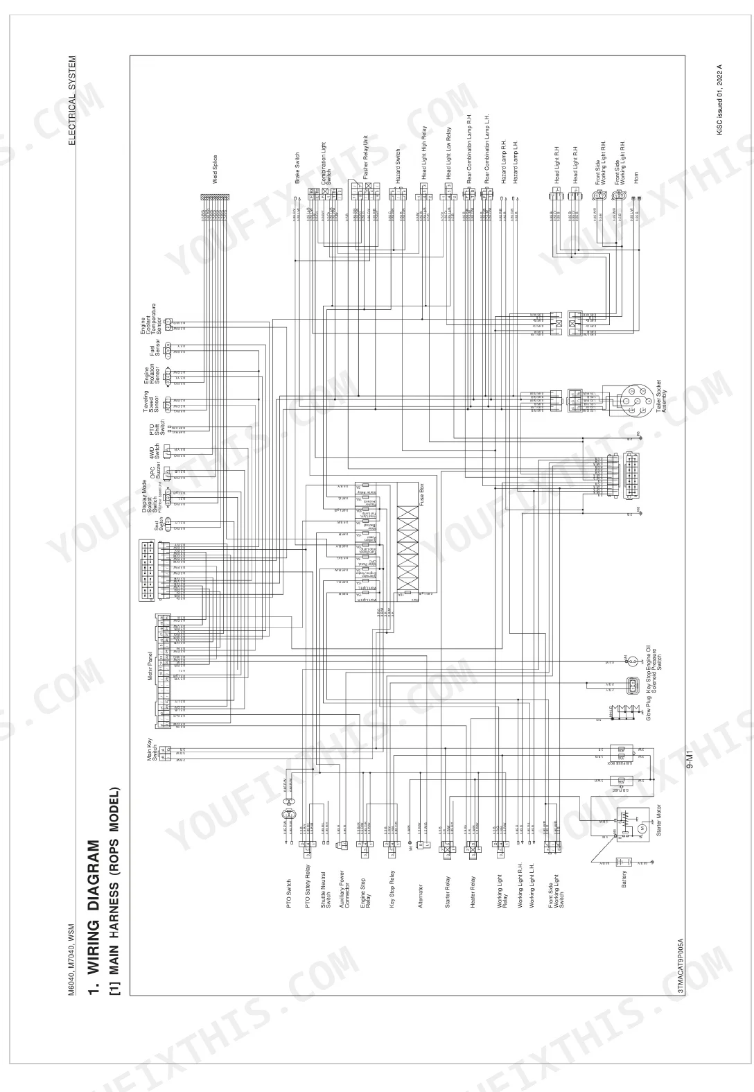


All 564 pages of this Kubota M6040, M7040 Workshop Manual (OEM #9Y021-13896) are built around one goal: putting your tractor back to factory spec without the guesswork. Inside, you get 4 pages of wiring diagrams covering main harness, cabin harness, and engine harness configurations for both ROPS and cabin models, plus hydraulic circuit schematics tracing the complete three-point hitch system and total hydraulic circuit. Open to 150 pages of step-by-step procedures spanning engine teardown, transmission disassembly (both hydraulic shuttle and synchro shuttle variants), wet disc brakes, front axle with M7040 limited-slip differential, and full hydrostatic steering. Fill the crankcase to 11 L after an oil change, top the transmission case to 56 L, and change that fuel filter every 400 hours. Your machine is down. Pull up the bookmarked PDF on your tablet, search any spec by keyword, and get back to wrenching.
What's Inside This Kubota M6040, M7040 Manual
| System | Pages | Key Topics |
|---|---|---|
| General | 20-106 | Tractor Identification (Model Name And Serial Numbers), Cylinder Number, Handling Precautions For Electrical Parts And Wiring (Battery, Fuse, Connector, Handling Of Circuit Tester) |
| Engine | 107-124 | Feature |
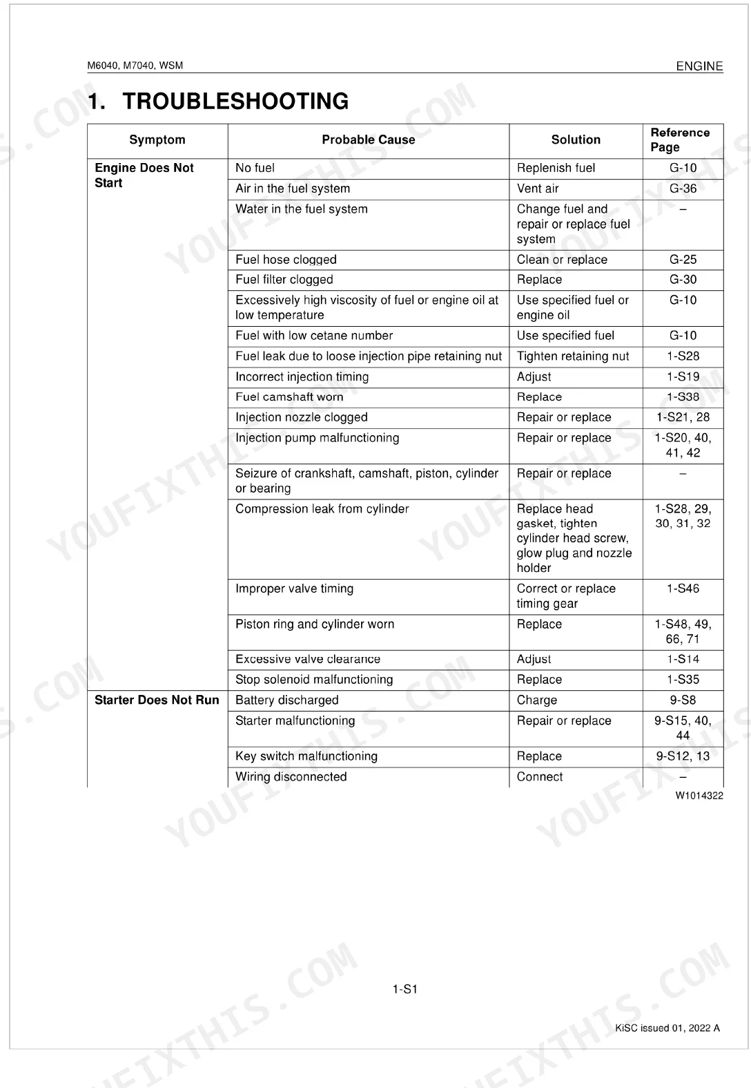
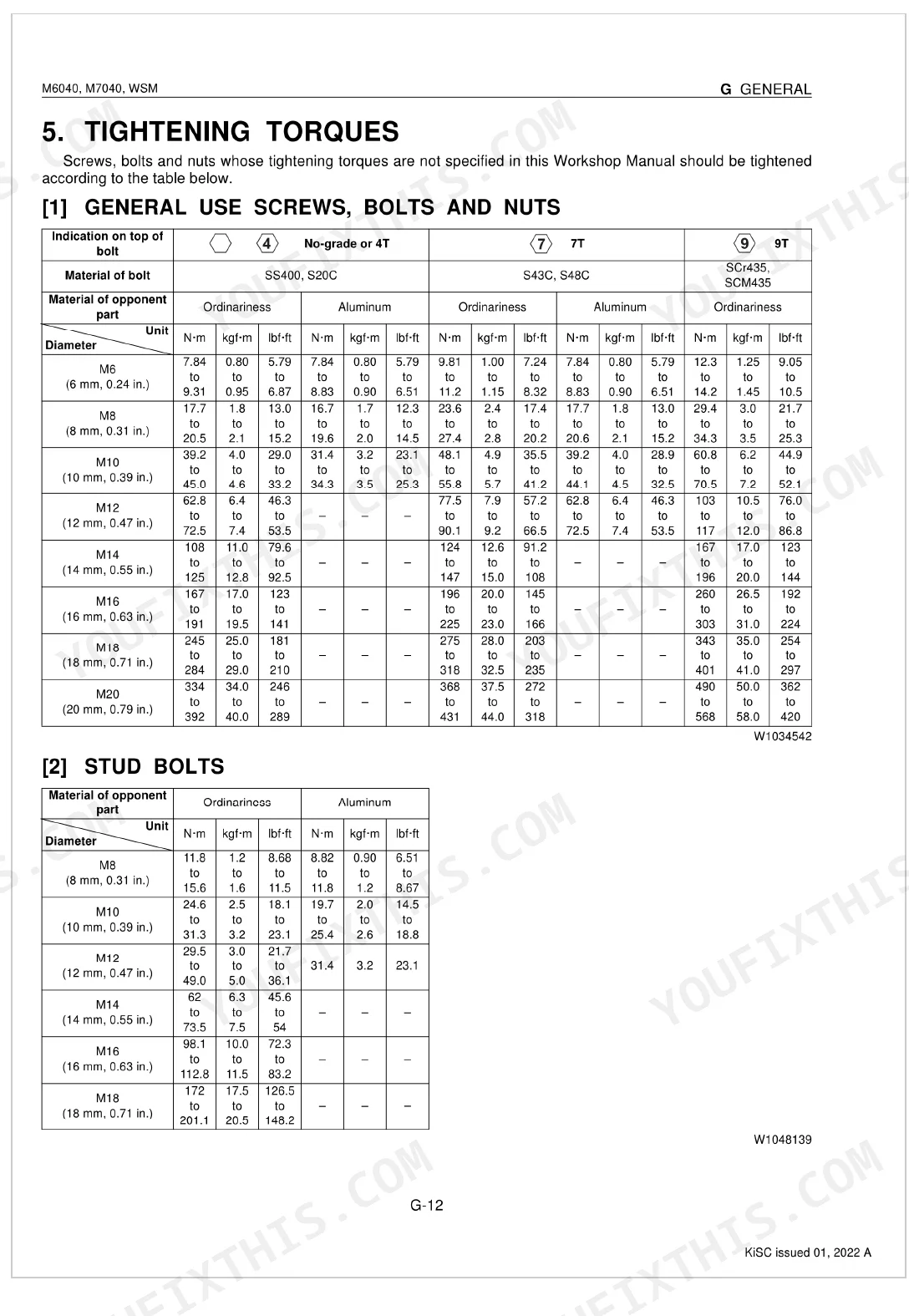
| Servicing Engine | 125-197 | Troubleshooting, Servicing Specifications, Tightening Torques, Checking, Disassembling And Servicing (Checking And Adjusting, Preparation, Disassembling And Assembling) |
| Clutch | 198-204 | Traveling Clutch (Structure, Oil Flow), PTO Clutch (Structure, Oil Flow, Valve) |
| Servicing Clutch | 205-235 | Troubleshooting, Servicing Specifications, Tightening Torques, Checking And Adjusting (Traveling Clutch, Pto Clutch) |
| Transmission | 236-253 | Structure (Hydraulic Shuttle Model, Synchro Shuttle Model), Power Train For Traveling Gear (Hydraulic Shuttle, Synchro Shuttle, Hydraulic Shuttle Valve, Hi-Lo/Creep Shift Section) |
| Servicing Transmission | 254-309 | Troubleshooting, Servicing Specifications, Tightening Torques, Checking And Adjusting (Shuttle Lever, Main Gear Shifting, Shuttle Valve) |
| Rear Axle | 310-312 | Structure, Power Transmission, Speed Reduction, Rear Axles Function |
| Servicing Rear Axle | 313-321 | Troubleshooting, Servicing Specifications, Tightening Torques, Disassembling And Servicing (Preparation, Disassembling And Assembling) |
| Brakes | 322-324 | Structure, Brake Pedal Type, Wet Disc Brakes, Parking Brake |
| Servicing Brakes | 325-332 | Troubleshooting, Servicing Specifications, Tightening Torques, Checking, Disassembling And Servicing (Checking And Adjusting, Disassembling And Assembling) |
| Front Axle | 333-337 | Structure (Wheel Drive, Limited Slip Differential [M7040]) |
| Servicing Front Axle | 338-365 | Troubleshooting, Servicing Specifications, Tightening Torques, Checking, Disassembling And Servicing (Checking And Adjusting, Preparation, Disassembling And Assembling) |
| Steering | 366-369 | Steering Mechanism, Full Hydrostatic Power Steering, Steering Cylinder |
| Servicing Steering | 370-387 | Troubleshooting, Servicing Specifications, Tightening Torques, Checking, Disassembling And Servicing (Checking And Adjusting, Preparation, Disassembling And Assembling) |
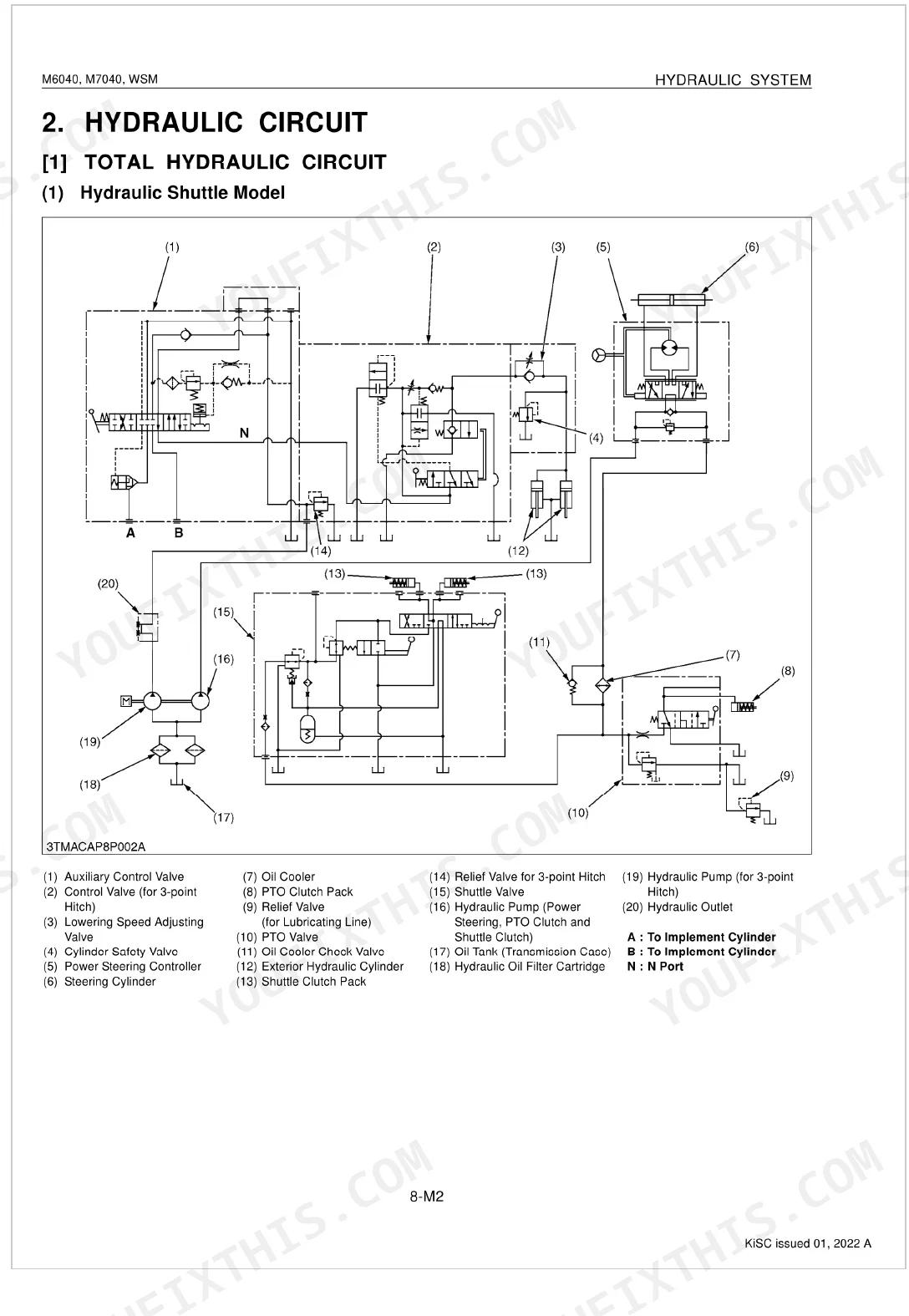
| Hydraulic System | 388-398 | Structure, Hydraulic Circuit (Total Hydraulic Circuit), Three Point Hitch Hydraulic System (Hydraulic Block, Linkage Mechanism, Hydraulic Cylinder) |
| Servicing Hydraulic System | 399-426 | Troubleshooting, Servicing Specifications, Tightening Torques, Checking And Adjusting (Hydraulic Pump, Relief And Safety Valve, Position And Draft Control Linkage) |
| Electrical System | 427-452 | Wiring Diagram (Main Harness, Cabin Harness, Engine Harness), Electrical Circuit Retailed Chart (Wiring Color), Starting System (System Outline And Electrical Circuit) |
| Servicing Electrical System | 453-500 | Troubleshooting, Servicing Specifications, Tightening Torques |
| Cabin | 501-510 | Air Conditioning System (Structure, Compressor, Air Conditioner Unit, System Control, Air Flow, Air Control Vent, Electrical System) |
| Servicing Cabin | 511-564 | Troubleshooting, Servicing Specifications, Tightening Torques, Precautions At Repairing Refrigerant Cycle (Handling Of Service Tools) |
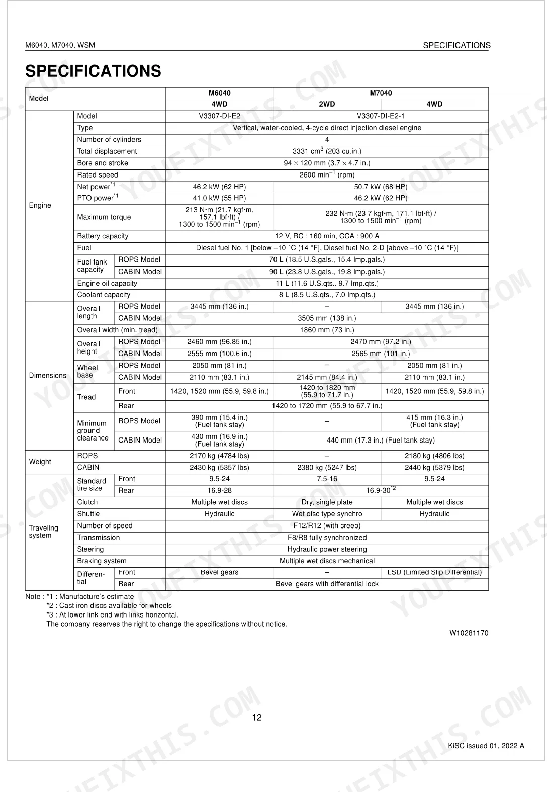
Quick Reference Specifications
| Specification | Value | Page |
|---|---|---|
| Engine crankcase (with filter) | 11 L (11.6 U.S.qts., 9.7 Imp.qts.) | p. 31 |
| Transmission case | 56 L (59.2 U.S.qts., 49.3 Imp.qts.) | p. 31 |
| Coolant | 8.0 L (8.5 U.S.qts., 7.0 Imp.qts.) | p. 31 |
| Engine oil change interval | every 200 Hr | p. 35 |
| Fuel filter replacement interval | every 400 Hr | p. 36 |
| Cylinder head mounting screw (bolt head with stamp "10") | 186 to 196 N-m (19.0 to 20.0 kgf-m, 137 to 145 lbf-ft) | p. 136 |
| Cylinder head mounting screw (bolt head with no stamp) | 165 to 175 N-m (16.9 to 17.8 kgf-m, 122 to 129 lbf-ft) | p. 136 |
| Engine Oil Capacity (with filter) | 11 L | p. 31 |
| Cylinder Head Mounting Screw Torque (Bolt head with stamp '10') | 186 to 196 N-m | p. 136 |
| Clutch Pedal Free Travel (Hydraulic Shuttle Model) | 15 to 25 mm | p. 209 |
| PTO Clutch Relief Valve Setting Pressure | 2.16 to 2.26 MPa | p. 210 |
| Transmission Case and Clutch Housing Mounting Screw and Nut (M14, 9T) Torque | 166.7 to 196.1 N-m | p. 258 |
Kubota M6040, M7040 Common Problems This Manual Covers
Kubota M6040/M7040 engine cranks slowly and won't fire in cold temperatures
Check each glow plug with a multimeter; resistance should be approximately 0.95 Ω (page 458). Replace any plug reading open or significantly out of spec. Verify preheat activates at key-on. If cranking is still sluggish, load-test the battery and inspect all ground straps. Engine oil capacity with filter is 11 L (page 31); top up if low, as thick cold oil increases cranking resistance.
Manual Section: Servicing EngineThree-point hitch won't raise implement or lifts too slowly under load p. 399
Verify hydraulic fluid level is correct. Check pump delivery: rated output is 38.3 L/min at rated pressure (page 401); low flow points to a worn pump or mis-set relief valve. Inspect position and draft control linkage adjustment in the Servicing Hydraulic System section (page 399). Clean or replace the hydraulic filter if overdue. Confirm the lowering valve and safety valve are seating properly.
Manual Section: Servicing Hydraulic SystemBrake pedal travels too far before engaging or braking force pulls to one side p. 325
Measure brake pedal free travel; correct spec is 40 to 45 mm (page 327). Adjust both pedals equally to prevent the tractor pulling during stops. Inspect the wet disc brake assemblies for contamination from transmission fluid leaks. If pedal feel is spongy, bleed the hydraulic circuit. Torque wheel mounting nuts to 260 to 304 N-m (page 316) after any service that required wheel removal.
Manual Section: Servicing BrakesPTO shaft won't rotate after engaging PTO switch, clutch appears to engage but no output p. 205
Check PTO clutch relief valve setting pressure; correct value is 2.16 to 2.26 MPa (page 210). Low pressure prevents the clutch pack from fully engaging under load. Inspect the PTO clutch valve for sticking or contamination. Verify the PTO engagement switch and its wiring circuit are intact. For a step-by-step fault isolation sequence, start at the Servicing Clutch section on page 205.
Manual Section: Servicing ClutchHard steering at low speeds or steering effort becomes uneven and unpredictable when turning p. 370
Inspect power steering fluid level and check for air entrainment in the circuit. Measure relief pressure and compare to spec in the Servicing Steering section (page 370). On 4WD models, verify front axle toe-in; correct range is 2.0 to 8.0 mm (page 341). Inspect the steering cylinder for internal seal leaks past the piston. If oil temperature climbs quickly during use, suspect a stuck relief valve or restricted return line.
Manual Section: Servicing SteeringTransmission gears slip out of engagement while driving or are difficult to shift into gear p. 254
Check transmission fluid level; capacity is 56 L (page 31). Inspect the shuttle lever and main gear shift linkage adjustment per the Servicing Transmission section on page 254. Worn synchro rings or weak detent springs typically cause gears to jump out under load. On any recent assembly, torque transmission case and clutch housing M14, 9T fasteners to 166.7 to 196.1 N-m (page 258).
Manual Section: Servicing TransmissionFrequently Asked Questions
What are the recommended service intervals?
The manual provides a detailed maintenance schedule with various service intervals. For example, daily checks are recommended, while engine oil and filter replacement is suggested every 200 hours. Other services, like cooling system flush, are recommended every 2 years.
What fluids and capacities does this machine require?
The machine requires specific fluids and capacities for various systems. For instance, the fuel tank capacity is 70 L (18.5 U.S.gals.) for ROPS models and 90 L (23.8 U.S.gals.) for CABIN models, using No. 2-D diesel fuel. The engine crankcase requires 11 L (11.6 U.S.qts.) of API Service Classification CD, CE or CF oil.
How to troubleshoot engine won't start?
If the engine won't start, common electrical problems include a blown fuse or slow blow fuse, defective engine stop solenoid, starter relay, key stop relay, PTO switch, or shuttle neutral switch. Mechanical issues can also prevent starting, such as a clogged fuel filter, malfunctioning injection pump, discharged battery, or compression leak from the cylinder.
What are the hydraulic system specifications?
The hydraulic pump for the three-point hitch has a delivery of Above 38.3 L/min and a relief valve setting pressure of 18.2 to 19.1 MPa. The position control rod length (ROPS) is approximately 159 mm, and the draft control rod length (ROPS) is approximately 146 mm.
What do I get after purchasing this Kubota M6040, M7040 manual?
You get a 564-page searchable PDF that downloads instantly after checkout. Open it on your laptop, tablet, or phone — bring it right to the shop floor.
Are there any print restrictions on this Kubota M6040, M7040 manual?
Yes, print as many copies as you want — there are no restrictions. Many mechanics print the section they need and bring it to the shop floor.
Can I find hydraulic circuit diagrams in this Kubota M6040, M7040 manual?
Included. Hydraulic system schematics cover all circuits, control valves, and component specifications for the Kubota M6040, M7040.
Document Quality
This document is a scanned PDF, not a native digital file. However, an OCR layer is present, so you can search the full text and copy content, which is a significant advantage. The text quality is consistently crisp and easy to read throughout the manual. Diagrams and illustrations are clear technical drawings, and all labels are readable, ensuring you can follow instructions accurately. Pages are clean with no noticeable scan artifacts, stains, or skewed content, and there are a few blank filler pages with only chapter titles.

Reviews
There are no reviews yet.