


This Kubota RTV900 workshop manual is the factory service documentation for the RTV900 utility vehicle, covering the D902-E-UV, D902-E2-UV, and D902-E3-UV diesel engines across serial ranges up to 4Z9999, from 5A0001, and the new RTV900 from serial 99438 and above. It runs 553 pages, organized into General, Mechanism, and Servicing parts.Coverage includes the engine, hydrostatic transmission, front and rear axles, brakes, steering, hydraulic system, and electrical system, plus dedicated sections for the hydraulic utility model, the new transmission, and the new RTV900. You get wiring diagrams, hydraulic circuits, torque values, factory specifications, and allowable limits.Owners, independent mechanics, and restorers can use it to diagnose a loss of drive, service the HST, adjust the brakes, replace worn drive shaft boots, or trace an electrical fault. It is a downloadable PDF you can search on any device or print by the page.
What's Inside This Kubota RTV900 Manual
| System | Pages | Key Topics |
|---|---|---|
| G General | 15-78 | Product Identification, Electrical Parts and Wiring, Lubricants, Fuel and Coolant, Screws, Bolts and Nuts, Plugs, Maintenance Check List |
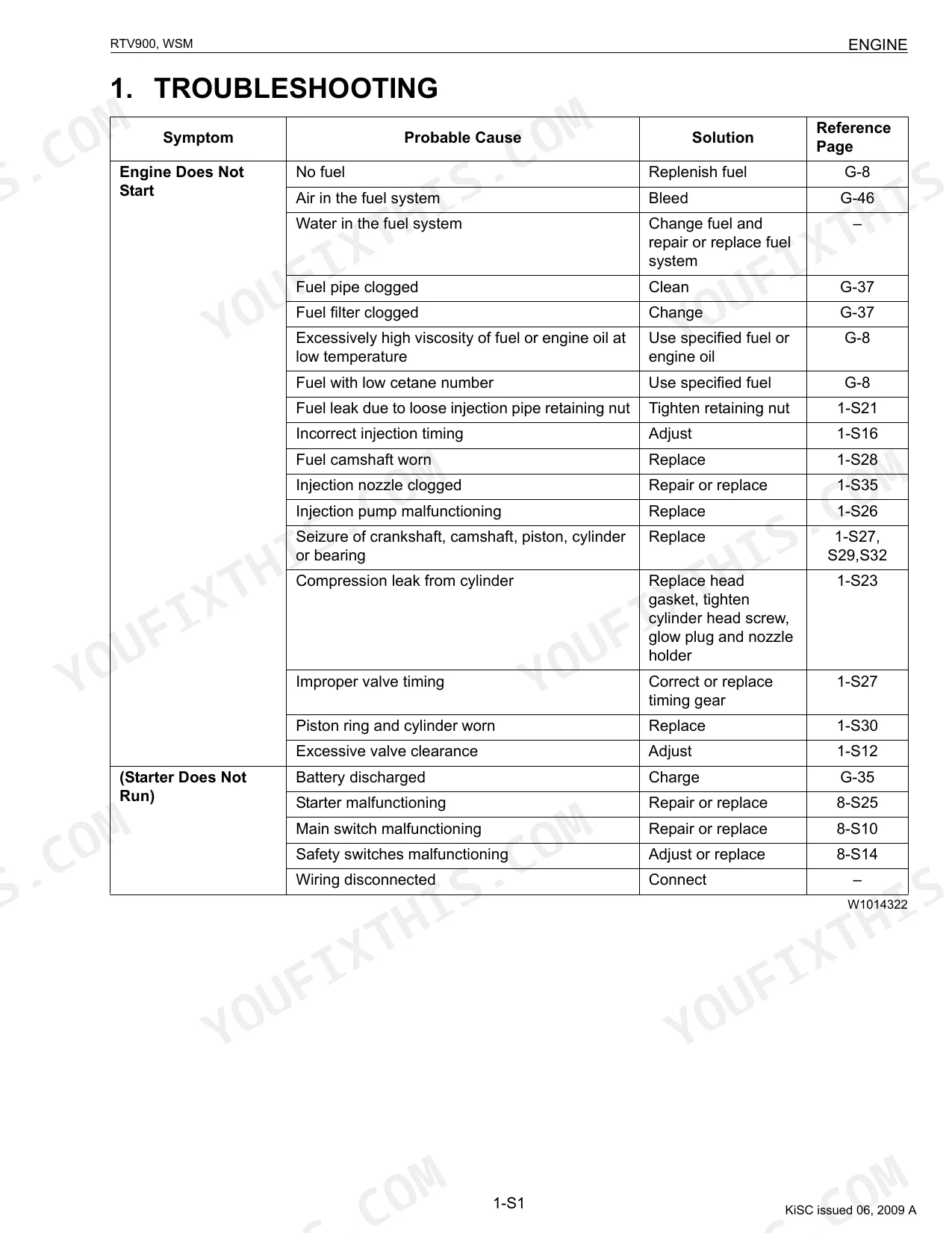
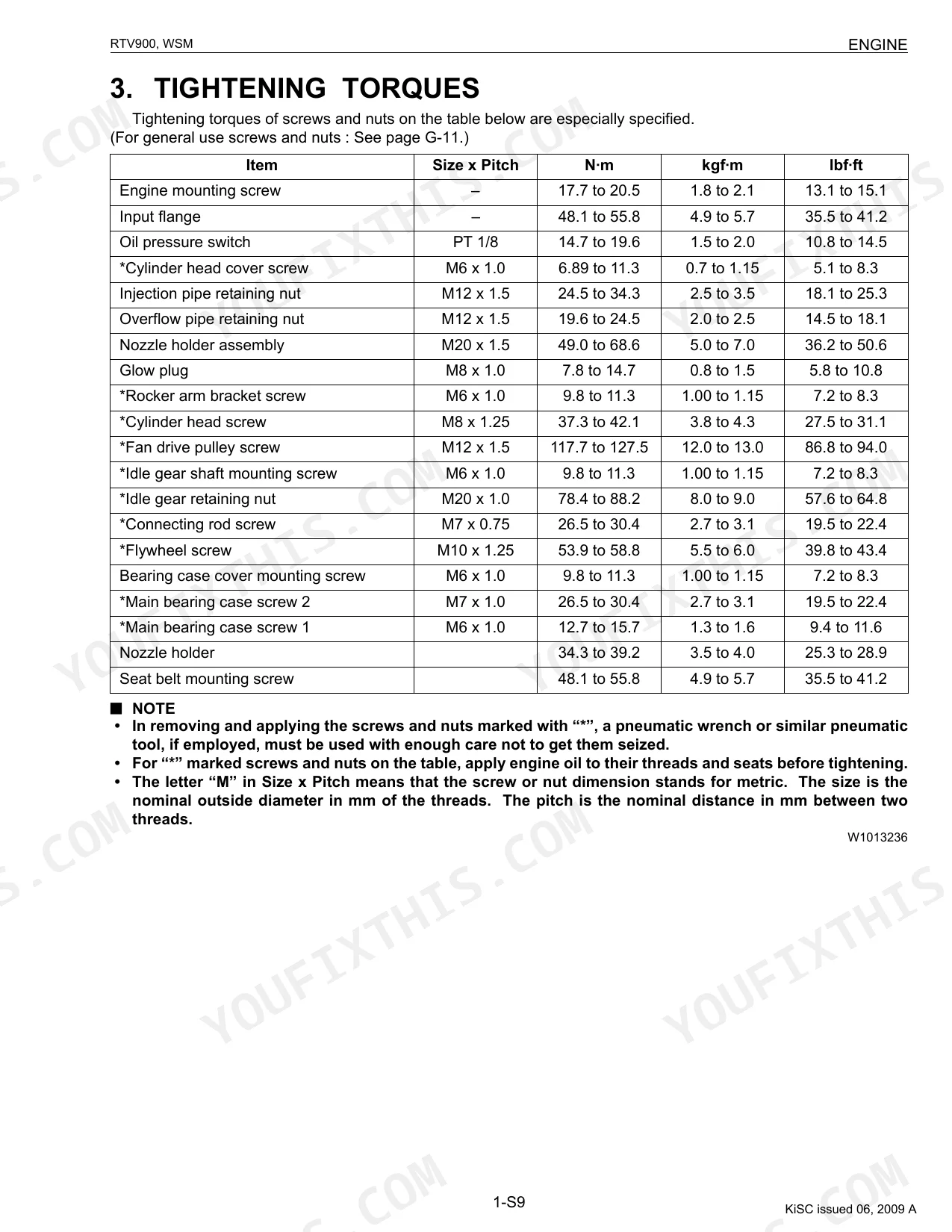
| Engine | 79-139 | Engine Body, Lubricating System, Cooling System, Fuel System, Cylinder Head and Valves, Crankshaft |
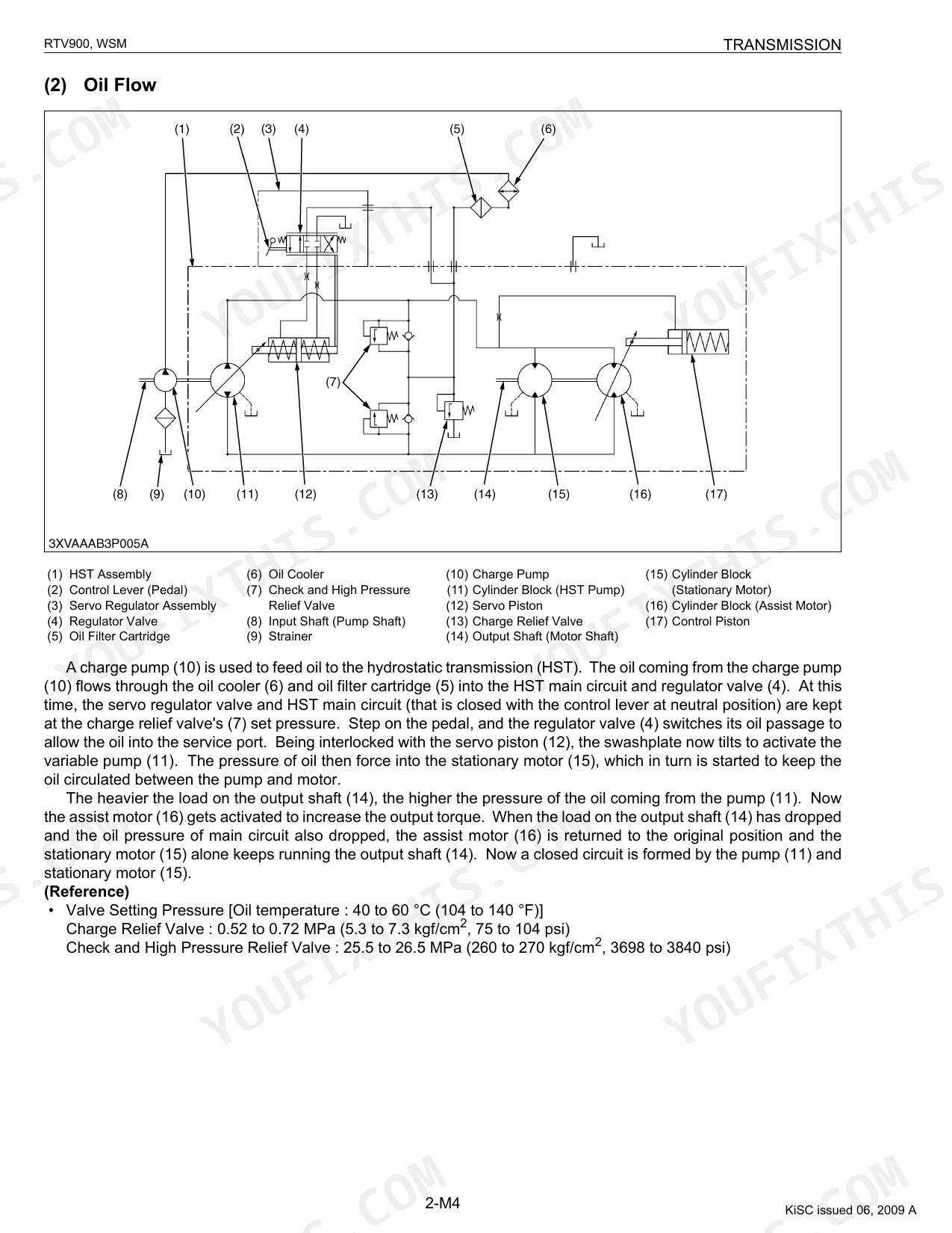
| Transmission | 140-209 | Hydrostatic Transmission (HST), Range Gear Shift Section, Front Wheel Drive Section, Bypass Valve, Front Case, Transmission Case |
| Rear Axle | 210-220 | Propeller Shaft, Leaf Spring, Shock Absorber, Bearing, Oil Seal |
| Brakes | 221-248 | Knuckle (Front Brake), Rear Brake, Master Cylinder, Parking Brake, Brake Disc, Friction Plate |
| Front Axle | 249-277 | Front Suspension, Differential Pinion, Differential Side Gear, Bevel Pinion Gear Assembly, Drive Shaft Boot |
| Steering | 278-297 | Steering Controller, Steering Cylinder, Hydraulic Pump, Hydraulic Circuit, Power Steering Hose |
| Hydraulic System | 298-323 | Hydraulic Circuit, Hydraulic Pump, Hydraulic Cylinder, Control Valve, Hydraulic Outlet Valve, Oil Cooler |
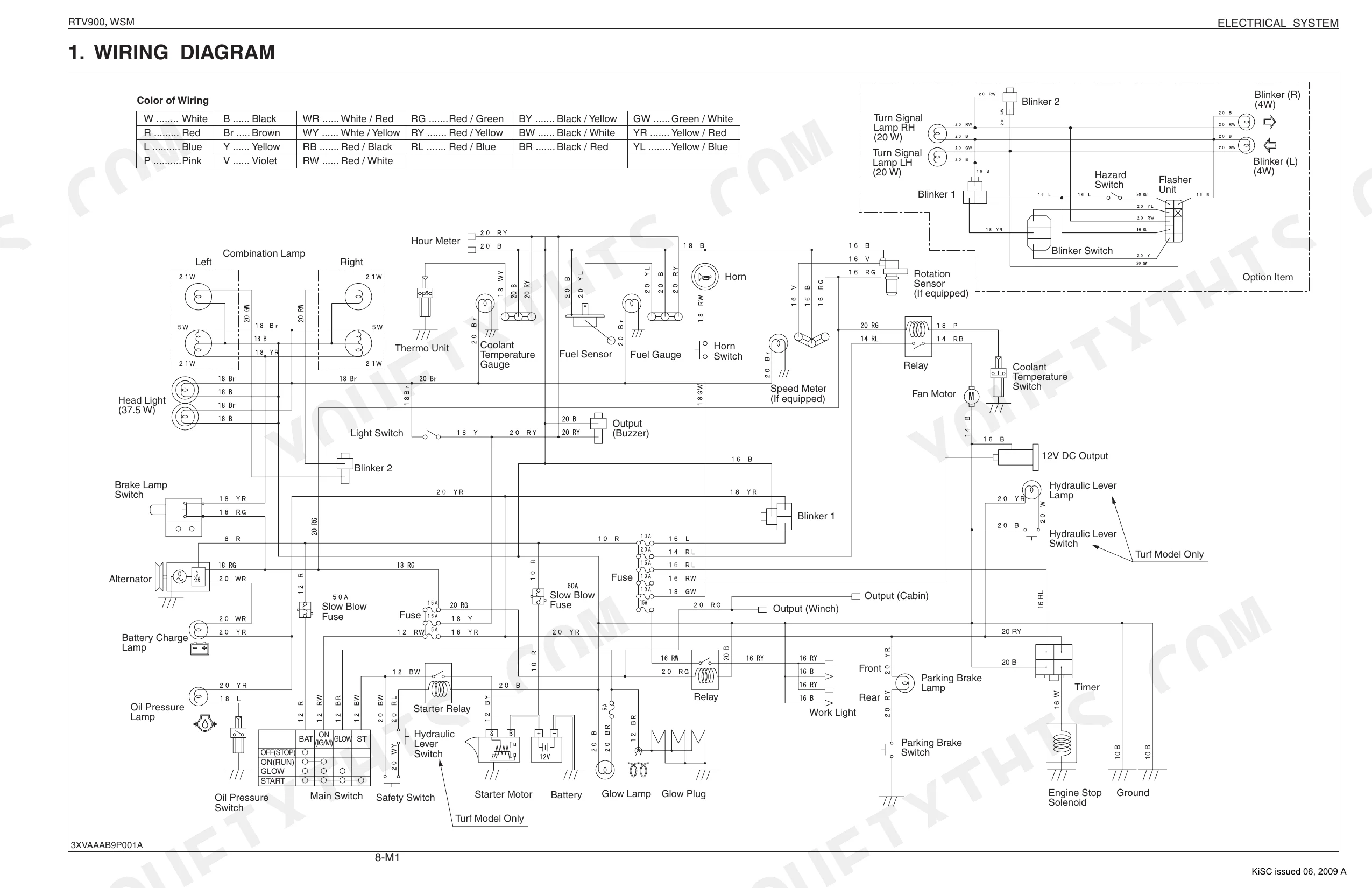
| Electrical System | 324-374 | Wiring Diagram, Starting System, Charging System, Lighting System, Cooling System, Gauges |
| Hydraulic Utility Model | 375-450 | Tractor Identification, Electrical Parts, Wiring, Battery, Fuse, Connector, Lubricants, Fuel |
| New Transmission | 451-478 | Bypass Valve, Control Linkage for Bypass Valve, Brake Rod, Transmission Fluid, Coolant, Battery, Cargo Bed, Muffler Cover |
| New Rtv900 | 479-553 | Transmission Mechanism, Safety Decals, Lubricants, Fuel, Coolant, Maintenance Check List, Tires, Power Train |
Quick Reference Specifications
| Specification | Value | Page |
|---|---|---|
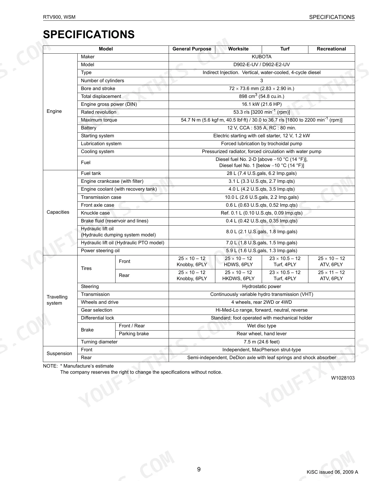
| Engine mounting screw torque | 17.7 to 20.5 N·m (1.8 to 2.1 kgf·m, 13.1 to 15.1 lbf·ft) | p. 95 |
| Rear wheel mounting screw torque | 75.0 to 90.2 N·m (7.6 to 9.2 kgf·m, 55.3 to 66.5 lbf·ft) | p. 215 |
| Relief valve setting pressure (Factory spec) | 14.7 to 15.7 MPa (150 to 160 kgf/cm², 2133 to 2276 psi) | p. 317 |
| Hydraulic lift oil filter (Yellow color) replacement interval | Initial 50 hours of operation | p. 29 |
| Oil filter bracket mounting screw torque | 18 to 20 N·m (1.8 to 2.1 kgf·m, 13 to 15 lbf·ft) | p. 520 |
| Air cleaner primary element replacement interval | Once yearly or after every sixth cleaning, whichever comes first | p. 50 |
| Radiator hose and clamp replacement interval | Every 2 years or earlier if checked and found that hoses are swollen, hardened or cracked. | p. 55 |
| Brake Pedal Play (Factory spec) | 7 to 14 mm (0.28 to 0.55 in.) | p. 231 |
| Brake Disc Thickness (Allowable limit) | 3.0 mm (0.118 in.) | p. 231 |
| Joint boot replacement condition | If the boots are cuts, cracked or deterioration, replace the new one. | p. 38 |
| Drive shaft boot replacement condition | Replace the internal circlip, boot and boot band with new ones. | p. 277 |
Kubota RTV900 Common Problems This Manual Covers
Vehicle loses drive under load
A loss of drive or a machine that will not move under load is a common RTV900 complaint tied to the hydrostatic transmission, low or contaminated hydraulic oil, or a clogged filter. The transmission section covers the HST, range gear shift, and bypass valve service.
Manual Section: 2 Transmission p. 140Engine overheats during operation
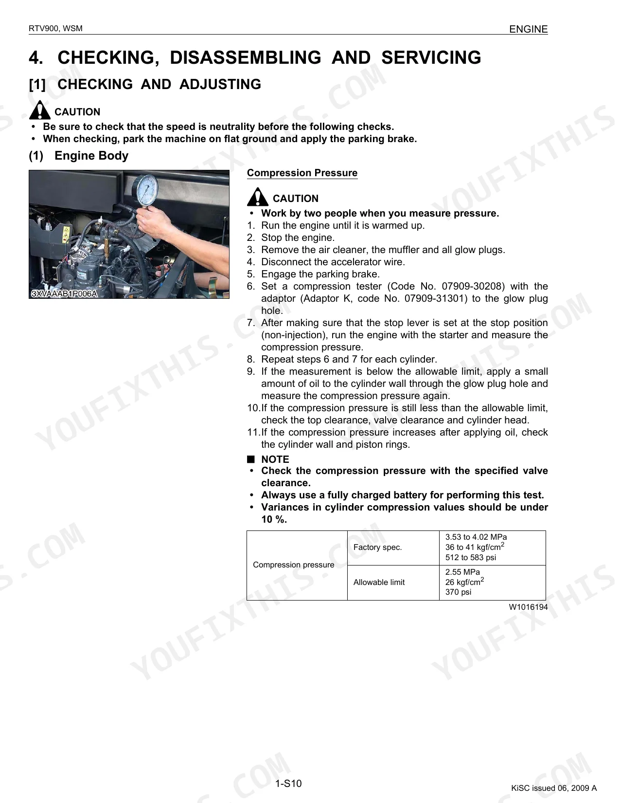
Overheating or a temperature warning during use often comes from a blocked radiator screen, a dirty cooling stack, or low coolant. The engine section covers the cooling system and related service.
Manual Section: 1 Engine p. 79Warning lamp stays on after start-up
A warning lamp that remains lit signals an abnormal condition detected by the Easy Checker system and should be investigated before further operation. The electrical section covers the wiring, gauges, and charging and starting systems.
Manual Section: 8 Electrical System p. 324Weak brakes or parking brake slips
Weak braking or a parking brake that will not hold is usually low fluid, worn friction plates, or an adjustment issue. The brakes section covers the front and rear brakes, master cylinder, parking brake, and friction plate limits.
Manual Section: 4 Brakes p. 221Torn drive shaft or joint boots
Clacking, binding, or a visibly split boot at the drivetrain lets contamination in and accelerates wear. The front axle section covers the drive shaft boot and the surrounding front axle and differential components.
Manual Section: 5 Front Axle p. 249Heavy or unresponsive steering
Hard steering or poor response points to the steering controller, cylinder, or hydraulic pump feeding the circuit. The steering section covers the controller, cylinder, and power steering hose service.
Manual Section: 6 Steering p. 278Frequently Asked Questions
Which machines and serial numbers does this manual cover?
It covers the Kubota RTV900 utility vehicle with the D902-E-UV, D902-E2-UV, and D902-E3-UV engines, including serials up to 4Z9999, from 5A0001, and the new RTV900 from 99438 and above.
Does it help with hydrostatic transmission problems?
Yes. The transmission section covers the hydrostatic transmission, range gear shift section, front wheel drive section, and bypass valve, with servicing procedures for diagnosing drive faults. p. 140
Are the wiring diagrams and electrical checks included?
Yes. The electrical system section provides the wiring diagram plus the starting, charging, lighting, and cooling circuits and gauges for tracing faults such as an Easy Checker warning lamp. p. 324
How will I receive this Service Manual?
Immediate download of the complete 553-page searchable Service Manual. Open it on any device, whether that's a laptop at your desk or a phone in the field.
Are there any print restrictions on this manual?
The PDF is DRM-free, so print whatever sections you want to take out to the shop. Standard letter or A4 paper works.
Are there hydraulic schematics in this Kubota RTV900 manual?
Included. Hydraulic system schematics cover all circuits, control valves, and component specifications for the Kubota RTV900.

Reviews
There are no reviews yet.