

Part of the Kubota Repair Manuals.
This Kubota MX4700 and MX5100 workshop manual is the factory service documentation for these tractors, built around the V2403-M-E3 and turbocharged V2403-M-TE3 diesel engines. It runs 417 pages and is organized into General, Mechanism, and Servicing content covering the tractor from identification and torque tables through full teardown.
Coverage spans the engine, clutch, transmission, rear axle, brakes, front axle, steering, hydraulic system, and electrical system. You get wiring diagrams, hydraulic pump flow-meter tests, relief valve and control valve procedures, cylinder specifications, and the operator presence control safety circuit, along with factory specifications and allowable limits.
Owners, independent mechanics, and restorers can use it to chase power loss under load, fix a loader circuit that has lost a function, adjust clutch and brake free play, service the steering controller, or trace a no-start through the safety switches. It is a downloadable PDF you can search on any device or print by the page.
What's Inside This Kubota MX4700, MX5100 Manual
| System | Pages | Key Topics |
|---|---|---|
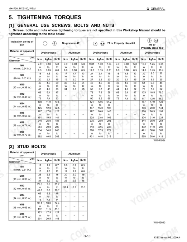
| G General | 14-83 | Tractor Identification, Cylinder Number, Electrical Parts, Wiring, Battery, Fuse, Connector, Circuit Tester |
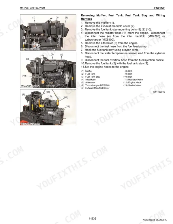
| Engine | 84-159 | Checking and Adjusting, Disassembling and Assembling, Cylinder Head and Valves, Piston and Connecting Rod, Crankshaft, Oil Pump |
| Clutch | 160-193 | Checking and Adjusting, Disassembling Clutch, Disassembling PTO Clutch, Travelling Clutch, Hydraulic PTO Clutch |
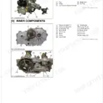
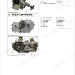
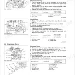
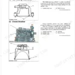
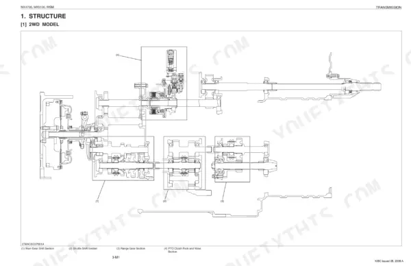
| Transmission | 194-250 | Separating Engine and Clutch Housing Case, Separating Clutch Housing and Mid Case, Disassembling Clutch Housing, Separating Mid Case and Transmission Case, Disassembling Mid Case |
| Rear Axle | 251-259 | Rear Axle Case, Rear Wheel, ROPS, Ball Bearing, Oil Seal, Lock Nut, Internal Snap Ring |
| Brakes | 260-273 | Brake Case, Brake Cam Lever, Parking Brake Lever, Brake Pedal, Brake Rod, Brake Lever Link, Turnbuckle, Oil Seal |
| Front Axle | 274-300 | Checking and Adjusting, Separating Front Axle, Disassembling 2WD Type Front Axle, Disassembling 4WD Type Front Axle, 2WD Type, 4WD Type |
| Steering | 301-324 | Hydraulic Pump Test Using Flow-Meter, Relief Valve, Hydraulic Pump, Steering Wheel and Steering Controller, Steering Cylinder |
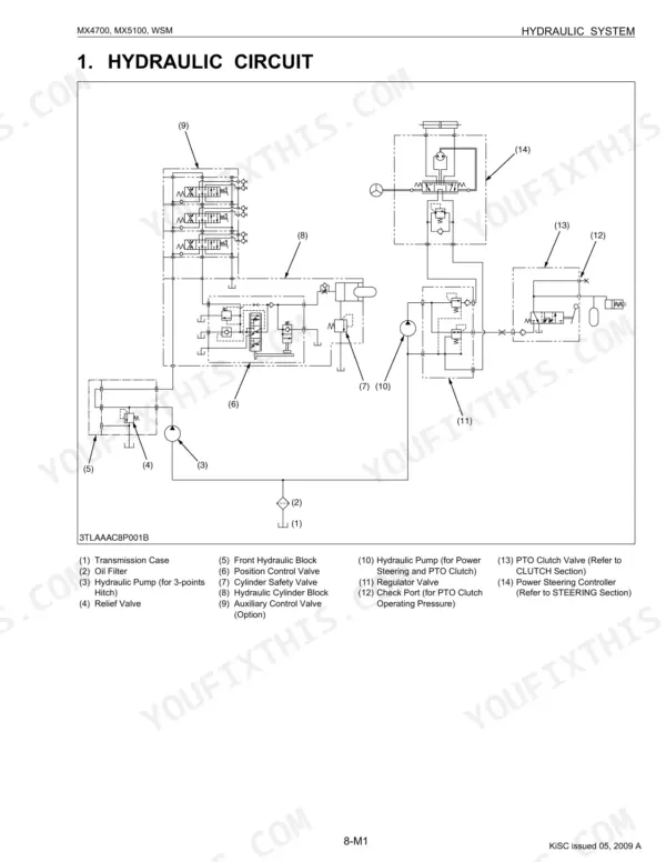
| Hydraulic System | 325-368 | Hydraulic Pump Test Using Flow-Meter, Relief Valve, Hydraulic Pump, Hydraulic Cylinder, Position Control Valve, Cylinder Safety Valve |
| Electrical System | 369-417 | Wiring Diagram, Engine Starting System, Opc (Operator Presence Control) System, Battery, Alternator, Safety Switch |
Quick Reference Specifications
| Specification | Value | Page |
|---|---|---|
| Front wheel mounting nut torque | 124.0 to 147.0 N·m | p. 285 |
| Rear wheel mounting screw and nut torque | 197 to 226 N·m | p. 285 |
| Power steering main delivery hose retaining nut torque | 46.6 to 50.9 N·m | p. 310 |
| Power steering turning delivery hoses retaining nut torque | 24.5 to 29.4 N·m | p. 310 |
| Regulator valve mounting screws torque | 17.6 to 20.6 N·m | p. 347 |
| Position control valve mounting bolt (M8) torque | 23.6 to 27.4 N·m | p. 347 |
| Hydraulic Cylinder Bore I.D. (Factory spec) | 90.000 to 90.050 mm | p. 346 |
| Hydraulic Cylinder Bore I.D. (Allowable limit) | 90.150 mm | p. 346 |
| Fuel filter element replacement interval | every 400 Hr | p. 27 |
| Engine oil filter replacement interval | every 200 Hr | p. 27 |
| Fan belt tension (deflection) | 12 mm (0.48 in.) at 98 N (10 kgf, 22 lbf) of force | p. 103 |
| Fan belt adjustment interval | every 100 Hr | p. 27 |