
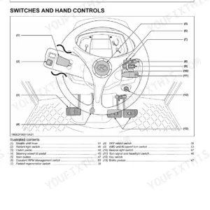
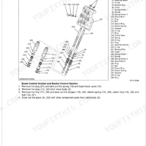
Part of the Kubota Repair Manuals.
This is the factory Kubota Workshop Manual covering the LA1301, LA1301S-1, LA1601, and LA1601S front loaders in one 45-page PDF (Kubota publication 9Y011-17011). A single manual serves all four models, including the serial number split below 10218 and above 10219.
It covers safety, loader terminology, and full specifications for each model, then a mechanism section explaining the hydraulic circuit, control valve, relief valve, and anti-cavitation operation. The servicing chapters add troubleshooting, servicing specifications, tightening torques, dismounting the loader, and cylinder and frame overhaul.
With it you can identify which torque and pressure values apply to your exact model, diagnose a loader that lifts slowly or drifts down, reseal the boom and bucket cylinders, and set the main and port relief valves. It downloads as a printable PDF for the shop, tablet, or phone.
What's Inside This Kubota LA1301–LA1601 Series Manual
| System | Pages | Key Topics |
|---|---|---|
| Safety Instructions | 3-5 | |
| Safety Decals | 6-8 | |
| Terminology | 9 | Bucket Cylinder, Boom, Mechanical Self Leveling Linkage, Mounting Pin, Side Frame, Hydraulic Control Valve, Bucket, Boom Cylinder |
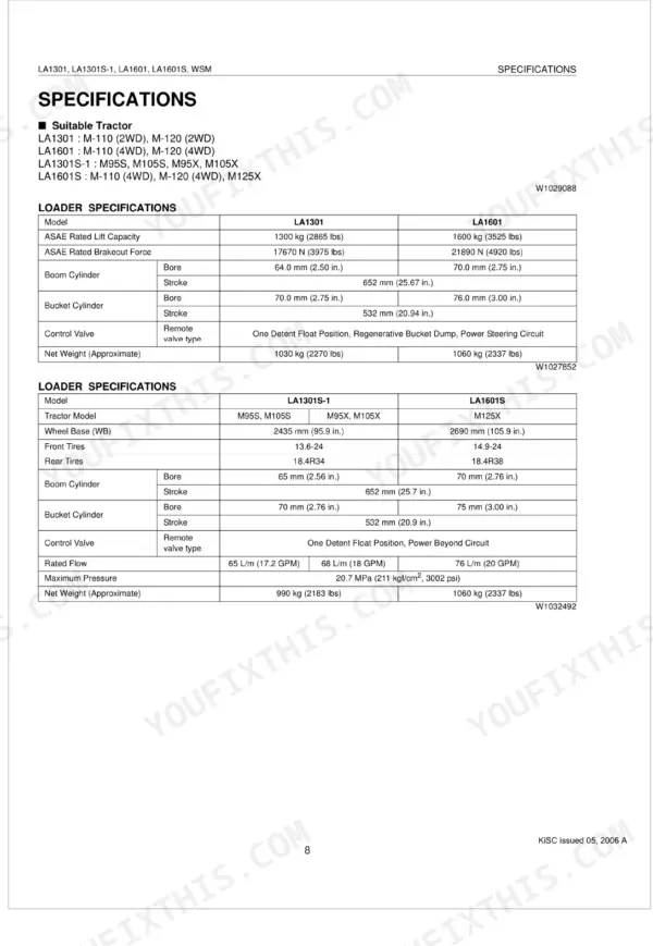
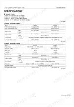
| Specifications | 10-13 | Suitable Tractor, Loader Specifications, Bucket Specifications, Operating Dimensions [LA1301, LA1601], Performance Ratings [LA1301, Dimensional Specifications [LA1301S-1 |
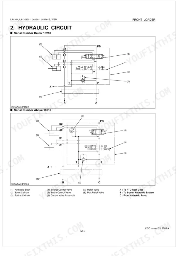
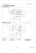
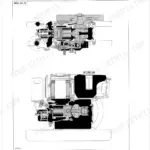
| Mechanism | 14-21 | Features, Hydraulic Circuit, Control Valve Assembly and Relief Valve, Boom Cylinder and Bucket Cylinder, Relief Valve, Relief Operation, Anti-Cavitation Operation |
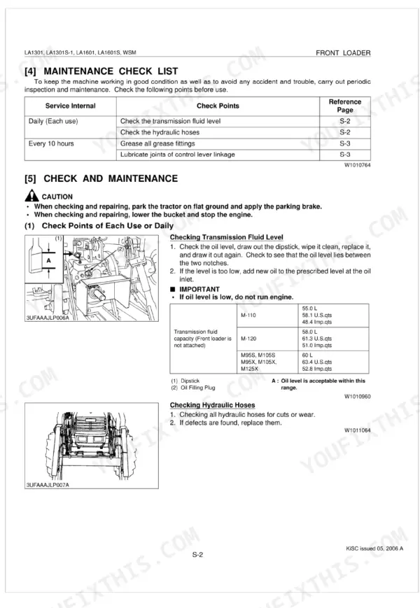
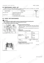
| Troubleshooting | 23-26 | Maintenance Check List, General, Check Points Every 10 Hours |
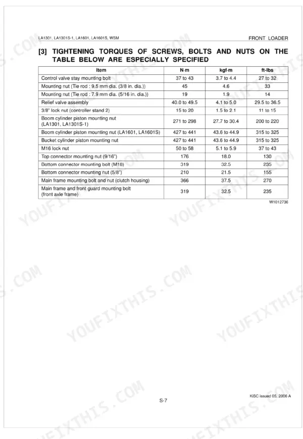
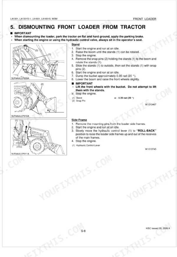
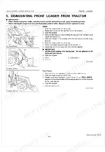
| Dismounting Front Loader From Tractor | 27-30 | Tightening Torques, Servicing Specifications, Tightening Torques of Screws, Bolts and Nuts |
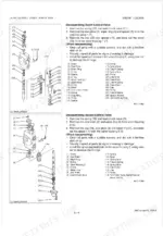
| Disassembling Control Valve | 31-34 | Checking, Disassembling and Servicing, Dismounting Hydraulic Hoses, Control Valve Cover and Cables |
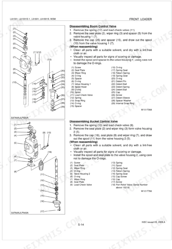
| Disassembling Boom Control Valve | 35-36 | Control Valve Separation of Section |
| Disassembling Controller and Cables | 37-38 | Controller Stand, Controller, Cables, Lock Lever, Cabin Bracket, Bucket, Boom, Hydraulic Cylinders |
| Disassembling Piston Rod Assembly | 39-40 | Cylinders Hydraulic Hoses |
| Installing O-Ring and Piston Seal | 41-42 | Piston Seal, O-Ring, Piston, Slide Jig, Correcting Jig, Piston Rod, Tool Box, Tool Box Stay |
| Front Guard and Main Frame | 43-44 | Main Frame Hydraulic Hoses |
Quick Reference Specifications
| Specification | Value | Page |
|---|---|---|
| All Models | ||
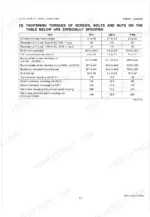
| Main frame mounting bolt and nut (clutch housing) tightening torque | 366 N-m (37.5 kgf·m, 270 ft-lbs) | p. 29 |
| Hose fitting and flare nut (3/4") tightening torque | 35 to 41 N-m (3.6 to 4.1 kgf·m, 26 to 30 ft-lbs) | p. 28 |
| Gap between boss and lock nut for hydraulic tubes | 2 to 3 mm (0.08 to 0.12 in.) | p. 39 |
| Bucket cylinder piston mounting nut tightening torque | 427 to 441 N·m (43.6 to 44.9 kgf·m, 315 to 325 ft-lbs) | p. 40 |
| Adapter and elbow (7/8") tightening torque | 77 to 85 N-m (7.9 to 8.7 kgf-m, 57 to 63 ft-lbs) | p. 34 |
| Relief valve setting pressure | 20.3 to 20.7 MPa (207 to 211 kgf/cm², 2950 to 3000 psi) | p. 32 |
| Control valve mounting bolt tightening torque | 37 to 43 N-m (3.7 to 4.4 kgf·m, 27 to 32 ft-lbs) | p. 33 |
| Relief valve setting pressure (Condition: Engine Speed: Maximum, Oil Temperature: 45 to 55 °C (113 to 131 °F)) | 20.3 to 20.7 MPa (207 to 211 kgf/cm², 2950 to 3000 psi) | p. 27 |
| M-110 | ||
| Transmission Case Capacity, M-110 | 55.0 L | p. 23 |
| M-120 | ||
| Transmission Case Capacity, M-120 | 58.0 L | p. 23 |
Kubota LA1301–LA1601 Series Common Problems This Manual Covers
Loader lifts slowly or weakly
Slow, weak, or no lift usually comes from low or aerated hydraulic fluid, a clogged suction path or filter, a worn control valve, or internal seal leakage. The servicing troubleshooting guidance walks these back to a cause.
Manual Section: Servicing p. 22Loader drifts down after lifting a load
A boom or bucket that settles under load points to internal leakage in the lift cylinders or control valve, or seals that let fluid bypass. The servicing chapter covers cylinder disassembly and seal replacement.
Manual Section: Servicing p. 22Hydraulics run noisy, jerky, or cavitate
Noise, jerky motion, or cavitation is often low oil, air ingestion, or contamination starving the pump. The mechanism section explains the relief valve and anti-cavitation operation that keep the circuit stable.
Manual Section: Mechanism p. 14Loader raises unevenly or binds
An attachment that will not raise evenly or binds in operation can have bent linkage, unequal cylinder wear, or mechanical damage. The servicing procedures cover checking and rebuilding the affected parts.
Manual Section: Servicing p. 22Oil leaks at hoses and fittings
Aged seals, cracked hoses, or loose fittings are the usual sources of weeping joints. The servicing tightening torque tables list hose fitting and flare nut values so connections seal without damage.
Manual Section: Servicing p. 22Relief valve pressure out of range
Poor lifting force can trace to a main or port relief valve set out of spec. The mechanism section documents the main relief setting of 20.3 to 20.7 MPa and, on serial numbers above 10219, the port relief valve.
Manual Section: Mechanism p. 14Frequently Asked Questions
Which loaders does this manual cover?
One workshop manual covers the Kubota LA1301, LA1301S-1, LA1601, and LA1601S front loaders, Kubota publication number 9Y011-17011, across the serial split below 10218 and above 10219.
Does it distinguish the serial number ranges?
Yes. It notes differences between serials below 10218 and above 10219, including the port relief valve fitted on loaders with serial numbers above 10219. p. 14
Which torque values apply to my model?
The servicing torque tables separate the models. The boom cylinder piston nut is 271 to 298 N-m on the LA1301 and LA1301S-1 and 427 to 441 N-m on the LA1601 and LA1601S; the bucket cylinder nut is 427 to 441 N-m and the main frame bolt is 366 N-m. p. 22
What is the relief valve pressure?
The mechanism section lists a main relief valve setting of 20.3 to 20.7 MPa and a port relief valve setting of 16.7 to 17.1 MPa on later serial numbers. p. 14
What format is this manual in?
This is a 45-page searchable PDF ready for immediate download. Works on any device -- pull it up on your phone while you're under the hood. No shipping, no waiting.
Can I print specific sections of this manual?
Yes. Print a chapter or just the pages for the job at hand, for use in your own shop. Any home or office printer works.
Does this Kubota LA1301–LA1601 Series manual cover the hydraulic system?
Yes -- complete hydraulic schematics with flow diagrams, valve configurations, and pressure specifications are included.



Reviews
There are no reviews yet.