

Part of the Kubota Repair Manuals.
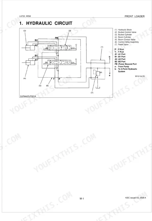
Kubota built the LA703 around a hydraulic circuit that moves 29.4 L/min and a control valve you can rebuild in your own shop, and this factory manual (OEM #9Y011-17261) walks all of it. The 46 pages open with hydraulic schematics, complete circuit and block layouts, then move into servicing work: control valve teardown, cylinder disassembly, and frame removal. A troubleshooting guide, maintenance checklist, and tightening torque tables for every bolt class round it out. Set the relief valve to 17.1-18.1 MPa before you call a weak-lift fault fixed, and torque the main frame M16 bolts to 226 N-m. Every hour the loader sits is money lost. Download the PDF, search any spec by keyword, and jump between sections with the built-in bookmarks.
Complete the set for your LA703
- Parts Catalog: Kubota LA703 Tractor Loader Parts Catalog
What's Inside This Manual
| System | Pages | Key Topics |
|---|---|---|
| Safety Instructions | 3-8 | |
| Loader Terminology | 9 | Hydraulic Control Lever, Side Frame, Mounting Pin, Main Frame, Boom Cylinder, Boom, Bucket Cylinder, Bucket |
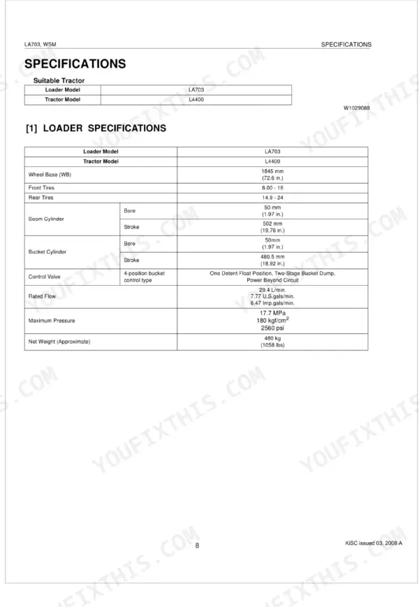
| Specifications | 10-13 | Loader Specifications, Bucket Specifications, Dimensional and Operational Specifications |
| Mechanism | 14-24 | Hydraulic Circuit, Hydraulic Block, Control Valve Assembly (Structure, Operation) |
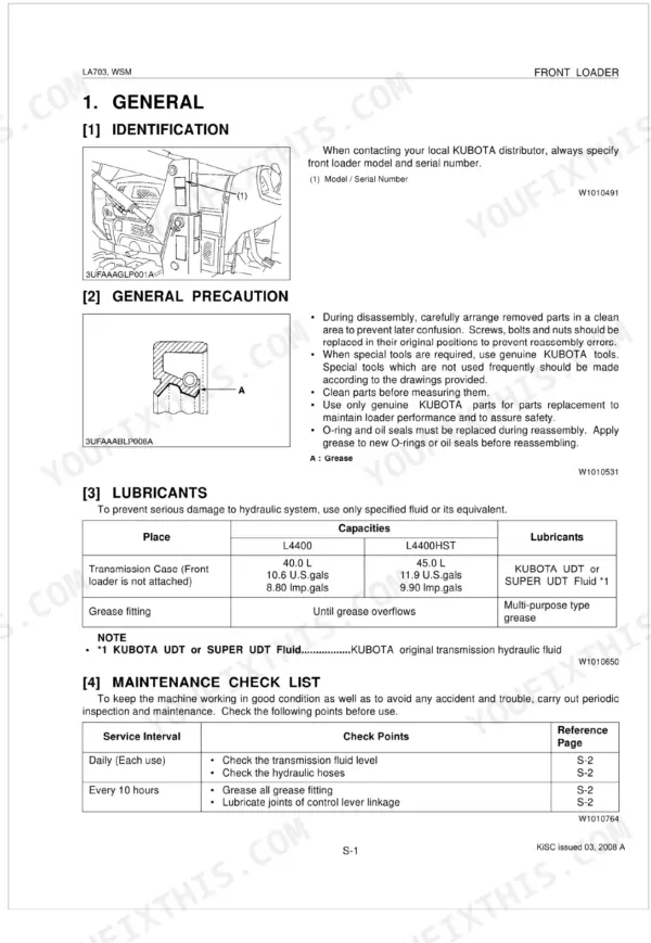
| Check and Maintenance | 26-27 | General |
| Servicing Specifications | 28-29 | Control Valve, Boom Cylinder, Control Lever, Hydraulic Pump, Oil Filter, Relief Valve, Hydraulic Hose, Boom Cylinder Tube |
| Hydraulic Fittings | 30-31 | Tightening Torques |
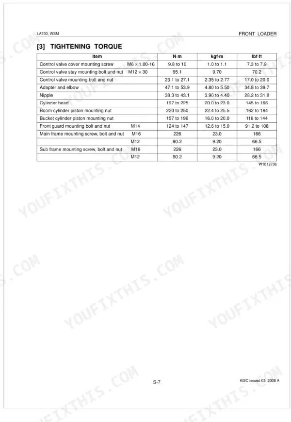
| Tightening Torque | 32 | Control Valve Cover, Control Valve Stay, Control Valve, Adapter and Elbow, Nipple, Cylinder Head, Boom Cylinder Piston, Bucket Cylinder Piston |
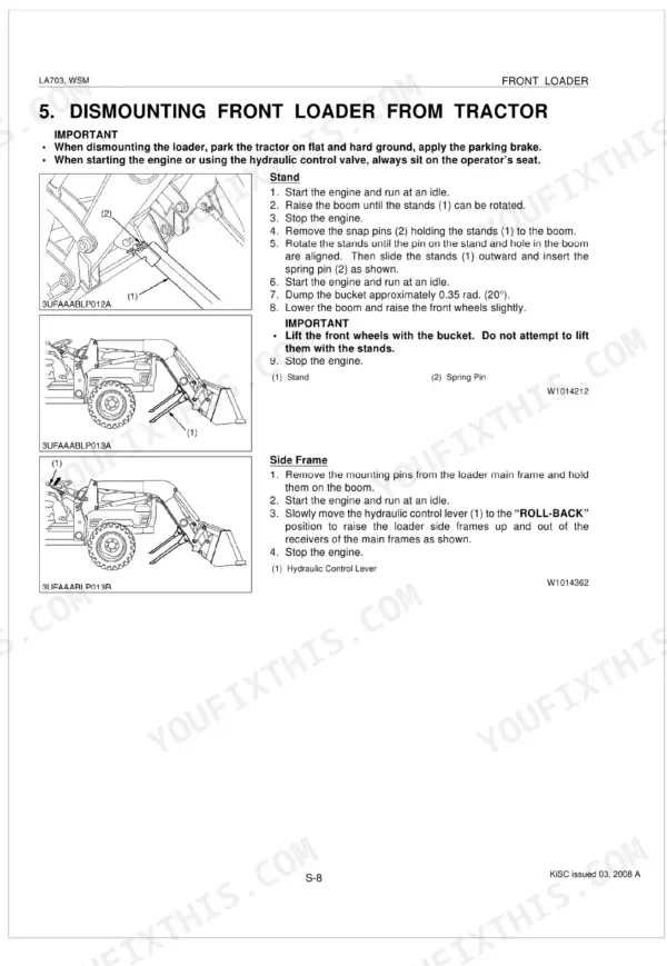
| Dismounting Front Loader From Tractor | 33-34 | Stand, Side Frame, Hoses, Hydraulic Control Lever, Protective Plug |
| Checking, Disassembling and Servicing | 35-38 | Control Valve, Hydraulic Hose, Control Valve Cover, Control Lever, Spool Plate, Rod 1, Bolt, Lever Guide |
| Bucket, Boom and Hydraulic Cylinders | 39-42 | Bucket, Boom, Hydraulic Cylinders, Piston Rod Assembly, Cylinder Head, Piston, Nut, Piston Seal |
| Side Frame, Main Frame and Others | 43-46 | Side Frame, Front Guard, Hydraulic Hoses, Control Valve, Main Frame, Sub Frame |
Quick Reference Specifications
| Specification | Value | Page |
|---|---|---|
| Relief valve setting pressure | 17.1 to 18.1 MPa, 175 to 185 kgf/cm², 2480 to 2620 psi | p. 29 |
| Main frame mounting screw, bolt and nut (M16) | 226 N-m, 23.0 kgf-m, 166 lbf·ft | p. 32 |
| Sub frame mounting screw, bolt and nut (M16) | 226 N-m, 23.0 kgf-m, 166 lbf·ft | p. 32 |
| Control valve mounting bolt | 23.1 to 27.1 N-m, 2.35 to 2.77 kgf·m, 17.0 to 20.0 lbf·ft | p. 36 |
| Hose fitting and flare nut (Brass, 9/16-18) | 16.3 to 17.6 N·m, 1.66 to 1.79 kgf·m, 12.0 to 13.0 lbf·ft | p. 31 |
| Hose fitting and flare nut (Steel, 9/16-18) | 24.4 to 27.1 N-m, 2.49 to 2.76 kgf·m, 18.0 to 20.0 lbf·ft | p. 31 |
| Control valve cover mounting screw (M6 x 1.00-16) | 9.8 to 10 N·m, 1.0 to 1.1 kgf·m, 7.3 to 7.9 lbf·ft | p. 32 |
| Control valve stay mounting bolt and nut (M12 × 30) | 95.1 N-m, 9.70 kgf.m, 70.2 lbf·ft | p. 32 |
| Piston Seal and Expander dimensions (LA703 Boom and Bucket) | A: 80 √, B: 0.157 rad (9°), C: 50.18 mm dia. (1.976 in. dia.), D: 51.18 mm dia. (2.015 in. dia.), E: 42.0 mm (1.65 in.), F: 10.0 mm (0.4 in.), G: 58.5 mm (2.30 in.), H: 14.0 mm (0.55 in.), I: 35.0 mm (1.38 in.), J: 0.122 rad (7°), K: 50.2 mm dia. (1.976 in. dia.), L: 58.9 mm dia. (2.32 in. dia.) | p. 41 |
| Boom cylinder piston mounting nut | 220 to 250 N·m, 22.4 to 25.5 kgf·m, 162 to 184 lbf·ft | p. 40 |
| Maximum Pressure | 17.7 MPa | p. 10 |
| Rated Flow | 29.4 L/min. | p. 10 |