


This is the factory Service Manual for the Manitou Z17/170Z compact excavator, publication number 50940107, built around the Yanmar 3TNV70-XBV diesel engine. Across 400 pages it walks a mechanic through engine measurement and overhaul, the hydraulic system and circuit schematics, removal and reinstallation of the hydraulic pump, control valve, swing motor and swivel joint, plus the machine's electrical equipment and wiring.With it you can measure engine compression, set valve clearances, check fuel injection pressure, work the pump, valve and travel-motor repairs, and follow the wear limits that keep a mini excavator digging. The Technical Data and Service Standards chapters give the specifications, clearances and tightening torques, while a dedicated troubleshooting chapter helps you trace bucket drift, discontinuous arm movement and no-start faults. The file is a downloadable PDF you can search, print and keep on the shop computer or a tablet at the machine.
What's Inside This Manitou America Z17, Z170Z Manual
| System | Pages | Key Topics |
|---|---|---|
| Forward | 3-8 | California Proposition 65 Warning, Diesel Engine Exhaust Warning, Battery Lead Compounds Warning |
| General Cautions for Maintenance Work | 9-20 | Correct Work, Safety Precautions, Preparations, Cautions for Disassembly and Reassembly, Cautions for Removal and Installation of Hydraulic Equipment |
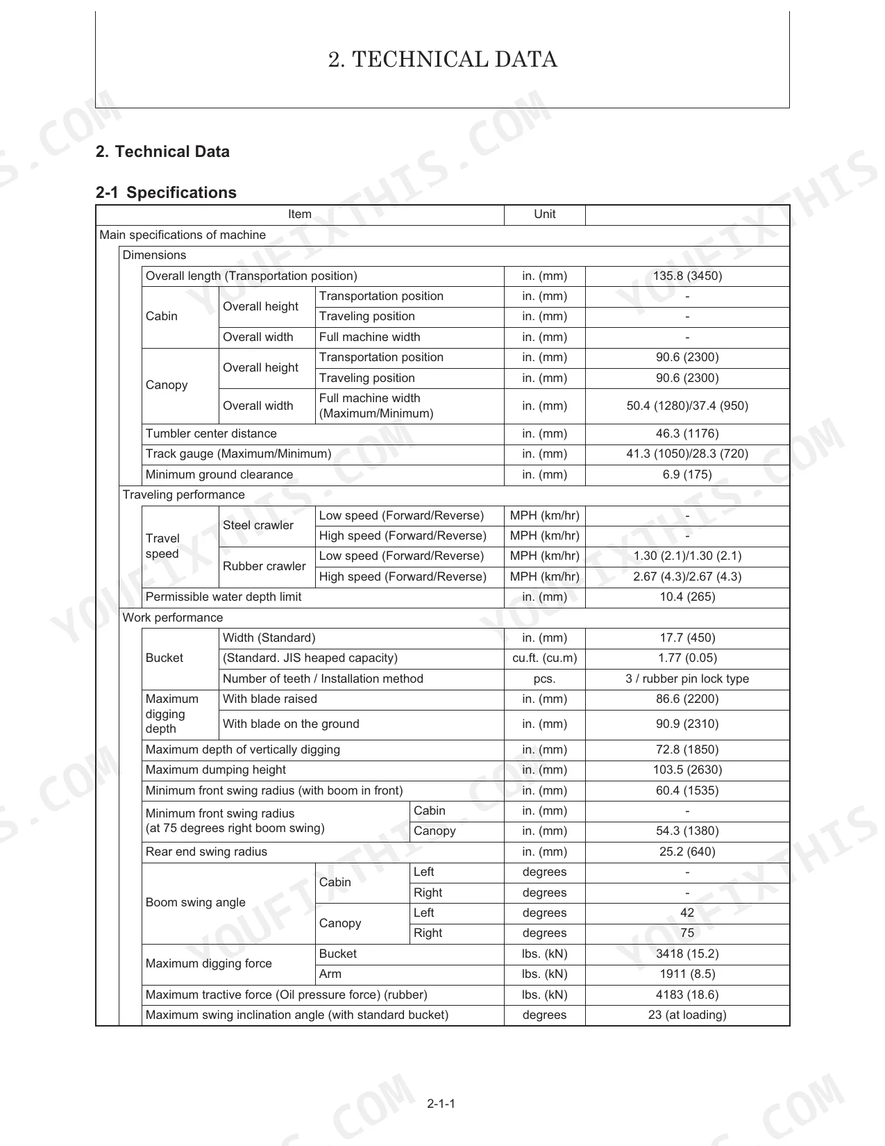
| Technical Data | 21-32 | Specifications, Outline Drawing and Working Area, Weight List of Main Parts, Lifting Capacity List |
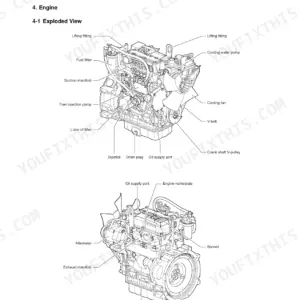
| Engine | 53-90 | Measurement |
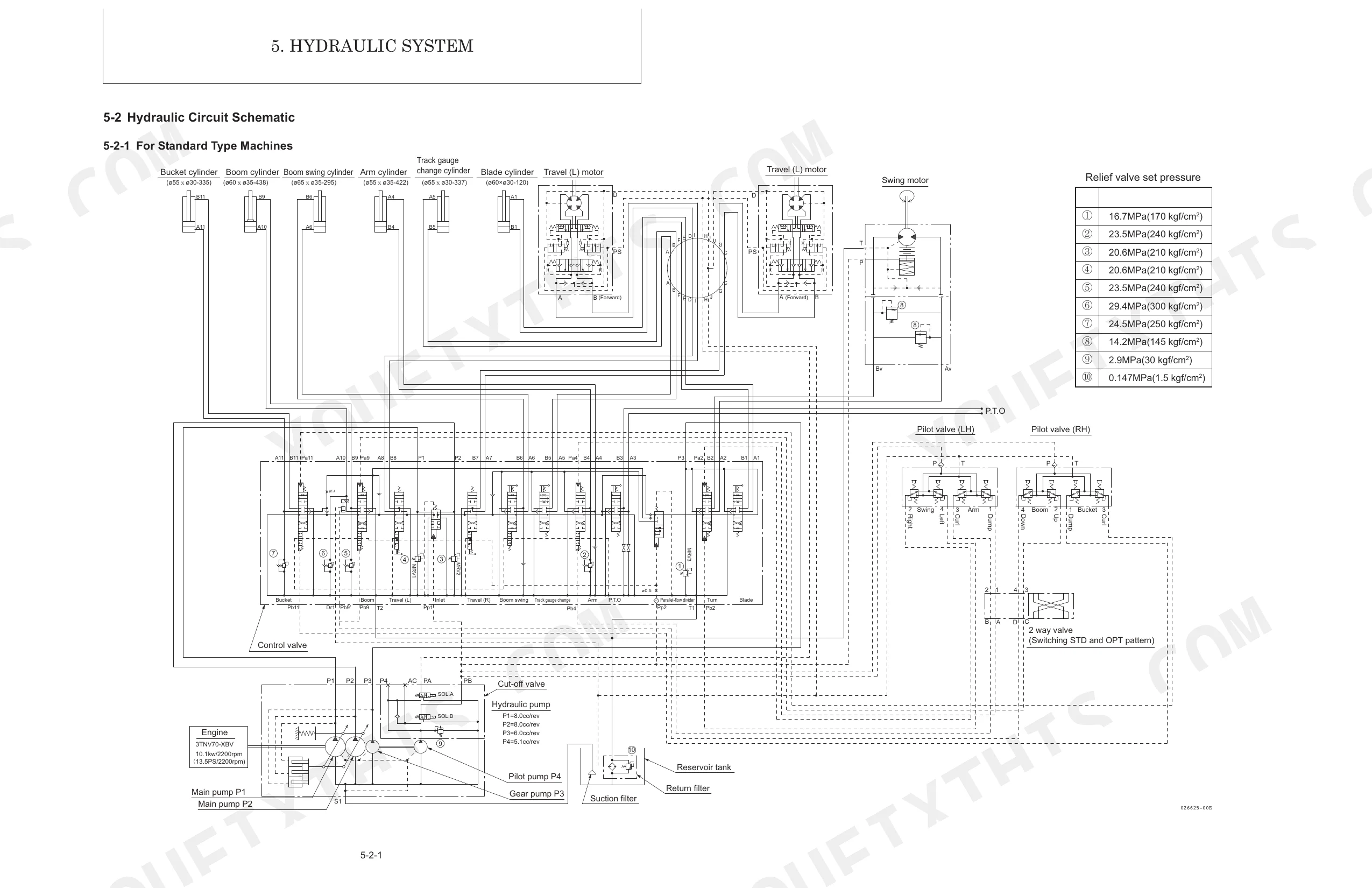
| Hydraulic System | 91-126 | Outline (Control Valve Operation, Additional Operation of Control Valve), Hydraulic Circuit Schematic (for Standard Type Machines) |
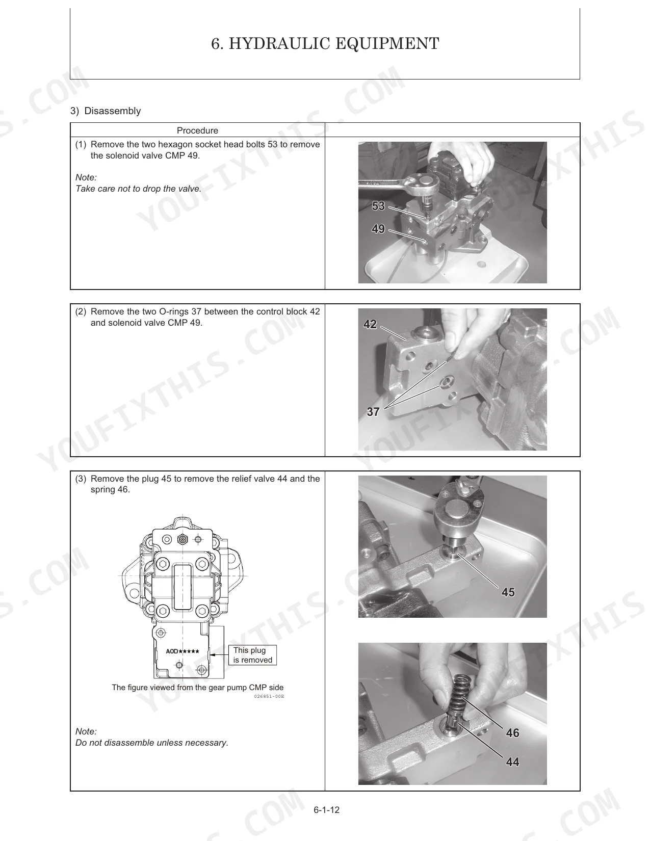
| Hydraulic Equipment | 127-264 | Removal and Reinstallation of Hydraulic Pump, Removal and Reinstallation of Control Valve, Removal and Reinstallation of Swing Motor, Removal and Reinstallation of Swivel Joint |
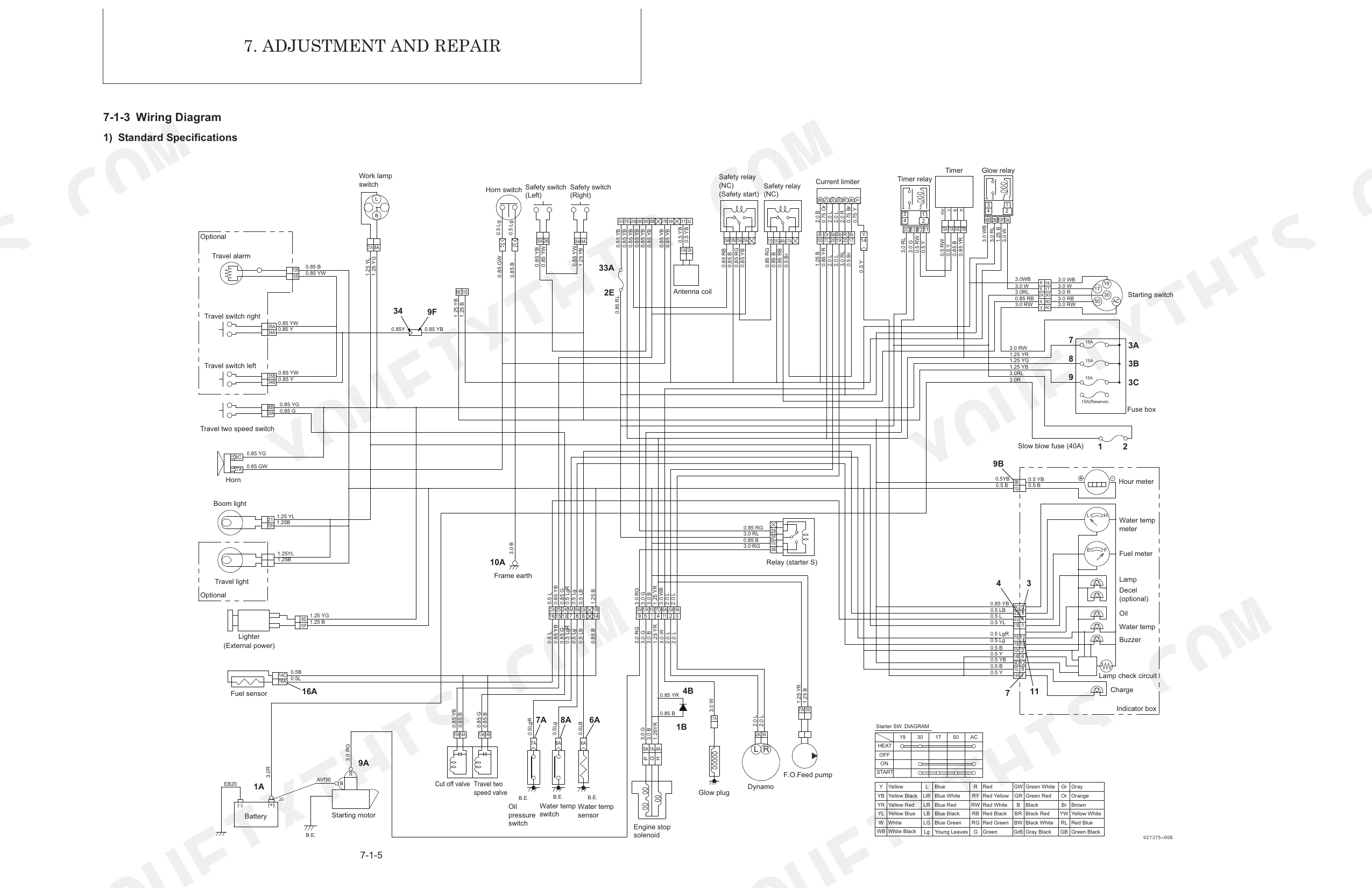
| Adjustment and Repair | 265-354 | Electric Equipment of Machine (Parts Layout of Electrical Equipment, Monitor and Alarm Systems, Wiring Diagram, Circuit Description of Engine Start and Stop, And Battery Charging, Removal and Reinstallation of Engine, Removal and Reinstallation of Starter Motor, Removal and Reinstallation of Fuel Injection Pump, Removal and Reinstallation of Fuel Tank, Removal and Reinstallation of Radiator) |
| Periodic Inspection and Servicing | 355-357 | List of Periodic Inspection and Servicing |
| Fuel, Lube Oil and Grease Recommended | 358-360 | Fuel, Lube Oil and Grease Recommended |
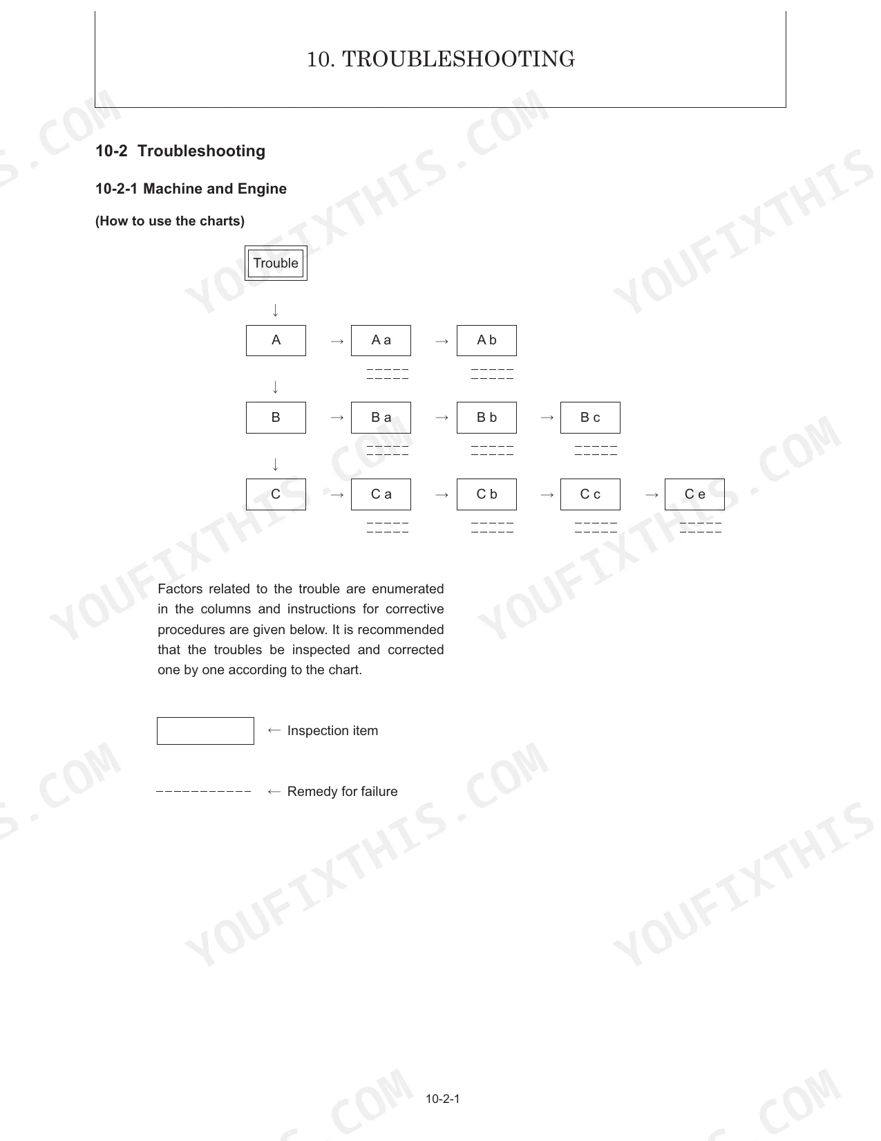
| Troubleshooting | 361-396 | Non-Breakdowns, Natural Release of Bucket, Discontinuous Arm Movement, Drifting of Upperstructure on Quick Travel Operation, Thermal Shock of Travel Motor |
| Reference Data | 397-400 | Specifications for Attachment, California Proposition 65 Warnings, Diesel Engine Exhaust Warning, Battery Lead Compounds Warning |
Quick Reference Specifications
| Specification | Value | Page |
|---|---|---|
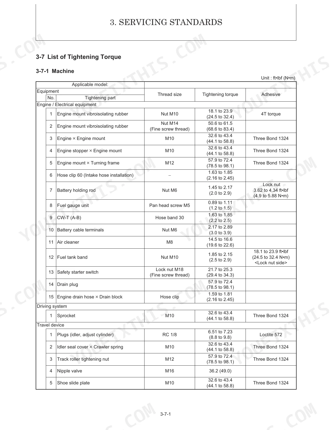
| Tightening torque for Hexagon head bolt (7T) Nut Coarse thread M10 × 1.5 | 32.6 to 43.4 ft•lbf (44.1 to 58.8 N•m) | p. 51 |
| Starter motor mounting bolt (M10) Tightening torque | 32.5 to 43.4 ft•lbf (44.1 to 58.8 N•m) | p. 87 |
| Battery voltage - 5 hrs rate capacity | 12-40 V-Ah | p. 28 |
| Suction filter Filtration accuracy | 150 Meshes | p. 25 |
| Tightening torque for parallel pipe thread G (PF) 1/4 | 16.7 to 20.3 ft•lbf (22.6 to 27.5 N•m) | p. 52 |
| Track roller & shaft B Wear limit | 2.48 (63) in. (mm) | p. 43 |
| Idler & shaft B Wear limit | Ø1.02 (Ø26) in. (mm) | p. 42 |
| Allowable clearance for Front Attachments pins and bushings | 0.04 in. (1.0 mm) | p. 46 |
| Allowable clearance for Bucket fulcrum pin and bore of bush or hole | 0.04 in. (1.0 mm) | p. 46 |
| Fuse A pcs. | 15x3, 40x1, 15x1 | p. 28 |
| Hydraulic oil tank capacity | 6.86 Gals (26 L) | p. 25 |
| Engine oil pan capacity | 3.0 Qts. (2.8 L) | p. 359 |
Manitou America Z17, Z170Z Common Problems This Manual Covers
Engine cranks but will not start
A dead battery, faulty starter motor, blown fuse or a safety-switch fault can all leave the engine turning over without firing. The engine start, stop and battery-charging circuit descriptions live in the Adjustment and Repair chapter.
Manual Section: Adjustment and Repair p. 265Weak or slow hydraulic functions
Low fluid, a clogged suction filter, air in the lines or internal pump wear show up as slow, weak or inconsistent hydraulics. Pump, control valve and swing-motor removal and reinstallation are covered here.
Manual Section: Hydraulic Equipment p. 127Bucket drifts down on its own
Natural release of the bucket and discontinuous arm movement are classic control-valve or cylinder-seal complaints. The Troubleshooting chapter separates these from normal non-breakdown behaviour and points to the cause.
Manual Section: Troubleshooting p. 361Tracks run too tight or wear fast
Improper track tension and worn rollers or idlers cause premature undercarriage wear and poor travel. The Service Standards chapter lists the roller and idler wear limits used to judge replacement.
Manual Section: Service Standards p. 33Engine overheats or loses power
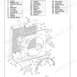
A restricted radiator, low coolant or a stuck thermostat leads to overheating and lost power under load. The Engine chapter covers checking the cooling water system and radiator for leakage.
Manual Section: Engine p. 53Electrical circuit or accessory stops working
A blown fuse, damaged wiring or a charging-system fault can kill a single circuit or accessory. The parts layout, wiring diagram and monitor and alarm systems are documented in the Adjustment and Repair chapter.
Manual Section: Adjustment and Repair p. 265Frequently Asked Questions
Which machine does this manual cover?
It is the Manitou Z17/170Z compact excavator Service Manual, publication number 50940107, covering the Yanmar 3TNV70-XBV engine across 400 pages.
Does it include torque and clearance specifications?
Yes. The Technical Data chapter lists specifications, weights and the tightening-torque values, and the quick reference gives clearances such as valve clearance and compression pressure. p. 21
Can it help me fix a drifting bucket or slow arm?
Yes. The Troubleshooting chapter addresses natural release of the bucket, discontinuous arm movement and upperstructure drift, with likely causes and checks. p. 361
Does it cover hydraulic pump and valve repair?
Yes. The Hydraulic System chapter gives the circuit schematics, and the Hydraulic Equipment chapter covers removal and reinstallation of the pump, control valve, swing motor and swivel joint. p. 91
What format is this Manitou America Z17/170Z manual in?
It's a 400-page searchable PDF, ready to download the moment you order. Open it on any device, including your phone out at the machine. Nothing ships and nothing waits.
Can I print this Manitou America Z17/170Z manual?
Yes. There's no DRM or copy protection, so print the whole manual or just the pages you need on any home or office printer.
Can I find wiring schematics in this Manitou America Z17/170Z manual?
Full wiring diagrams are included, mapping the electrical circuits, harness routing, and connector pinouts on the Manitou America Z17/170Z.


Reviews
There are no reviews yet.