


This is the service manual for the Gehl VT320, also sold as the Mustang and Manitou 3200VT track loader, factory publication 50940548. Its 356 pages cover the machine powered by the TCD 3.6 L4 diesel engine.The manual runs from safety and machine orientation through scheduled maintenance of the engine, cooling, fuel, DEF, and hydraulic systems, then into the full hydraulic schematic showing the lift and tilt cylinders, gear pump, base pump, drive motor, and control valve. It closes with wire harness diagrams and complete chassis, engine, seat, and cab electrical schematics.You get fluid capacities, engine output and torque figures, battery and fuse specifications, filter intervals, and fastener torque values, giving owners and technicians the diagrams and data to diagnose hydraulic, drive, and electrical faults on this compact track loader.
What's Inside This Manitou Group VT320, 3200VT Manual
| System | Pages | Key Topics |
|---|---|---|
| Safety | 9-26 | Safety Symbol and Signal Words, Mandatory Safety Shutdown Procedure, Electrical Energy, Maintenance and Service Safety Practices, Battery Hazards, Fire Hazards, Additional Safety Equipment |
| Introduction | 27-32 | Contents and Use of This Manual, Machine Orientation, Component Identification, Machine Model and Serial Number Locations, ROPS/FOPS Certification Label, Indicator and Operation Symbols, Machine Controls and Operation |
| Maintenance | 33-68 | Maintenance Schedule, Checks, Cleaning and Inspection, Lubrication and Filter Changes, Engine Maintenance, Electrical System, Air Conditioning Maintenance, Windshield Washer Reservoir |
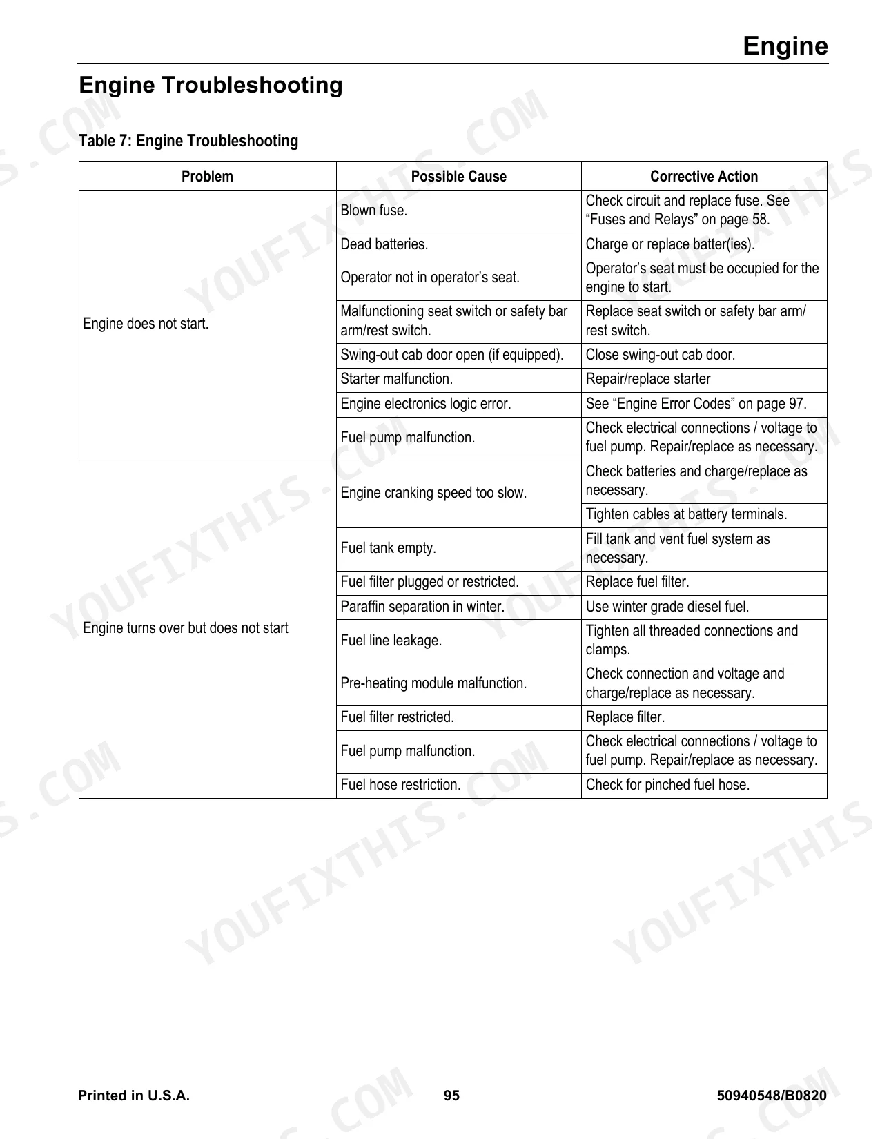
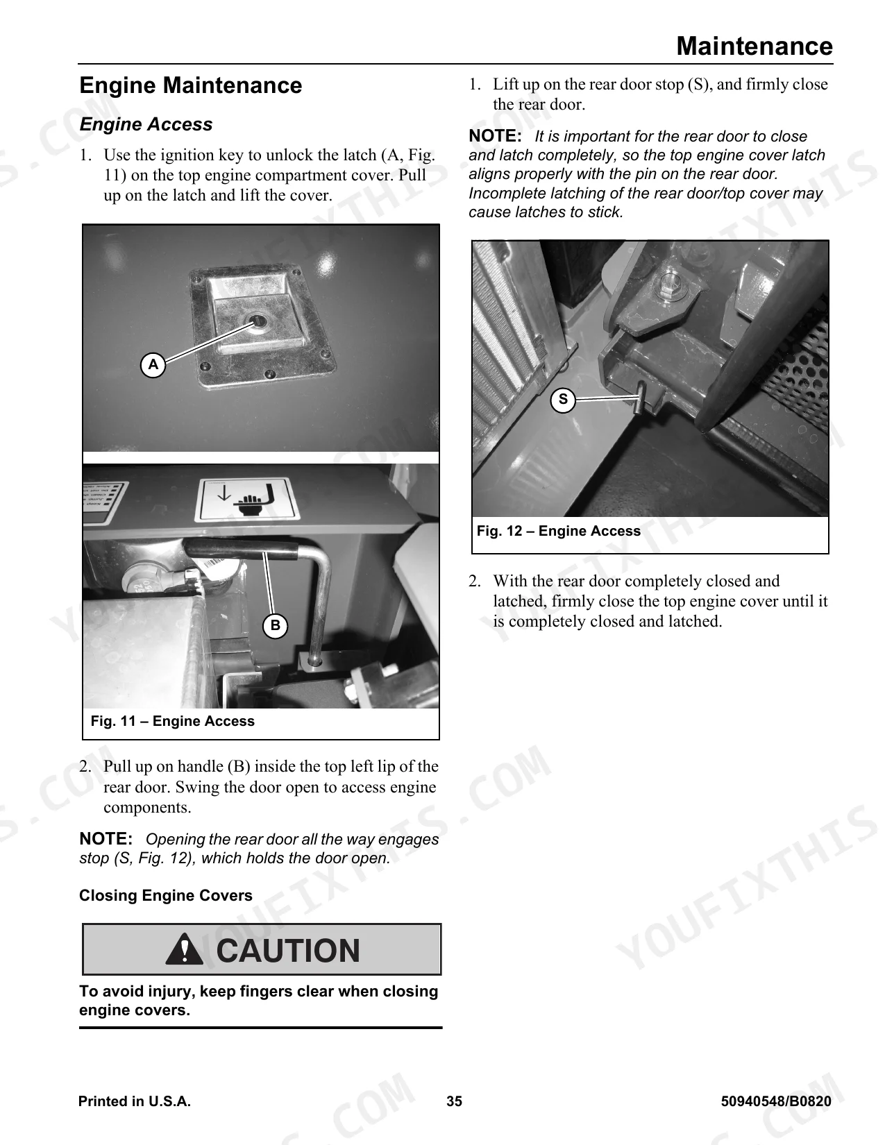
| Engine | 69-116 | General Information, Engine Access, Engine Maintenance, Engine Cooling System, Engine Removal/Installation, Diesel Exhaust Fluid (DEF) Service, Fuel System Maintenance |
| Cooling System | 117-136 | General Information, Radiator/Coolers Removal, Radiator/Coolers Installation |
| Hydrostatic Drive System | 137-182 | Hydrostatic Drive Pump, Hydrostatic Pump Relief Valves, Travel Drive Troubleshooting, Neutral Centering Check/Adjustment, Hydrostatic Pump Removal and Installation, Travel Motors, Tracks |
| Work Hydraulics | 183-218 | General Information, Hydraulic Hoses/Tubes, Seals, Main Pressure Test and Adjustment, Hydraulic Gear Pump, Control Valve, Tilt/Lift Cylinder Service/Tests |
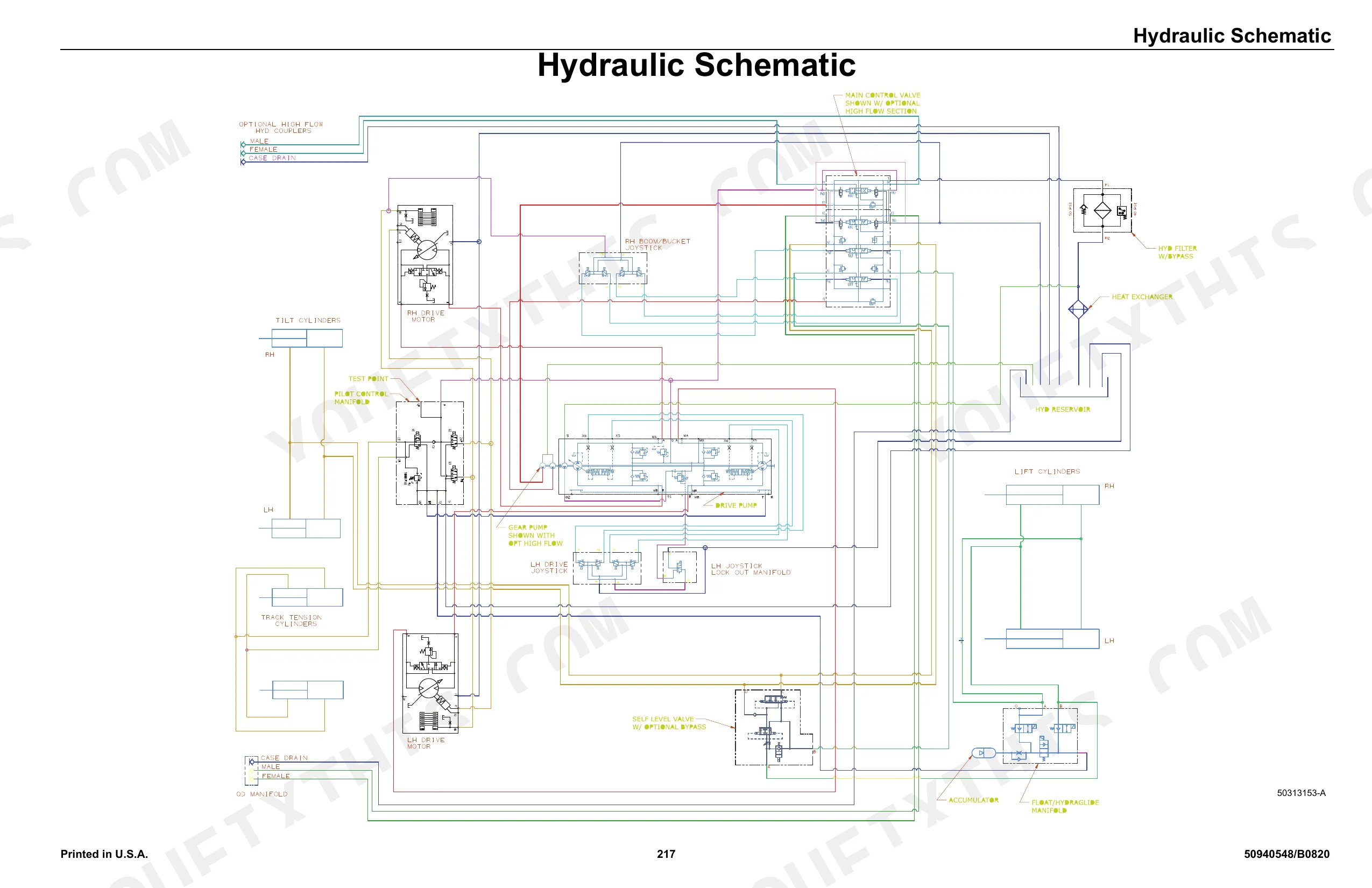
| Hydraulic Schematic | 219-284 | Lift Cylinders, Tilt Cylinders, Gear Pump, Base Pump, Drive Motor, Control Valve |
| Wire Harness Diagrams | 285-292 | Chassis Wire Harness Diagram (Page 1 of 2), Chassis Wire Harness Diagram (Page 2 of 2), Engine Wire Harness Diagram (Page 1 of 3), Engine Wire Harness Diagram (Page 2 of 3) |
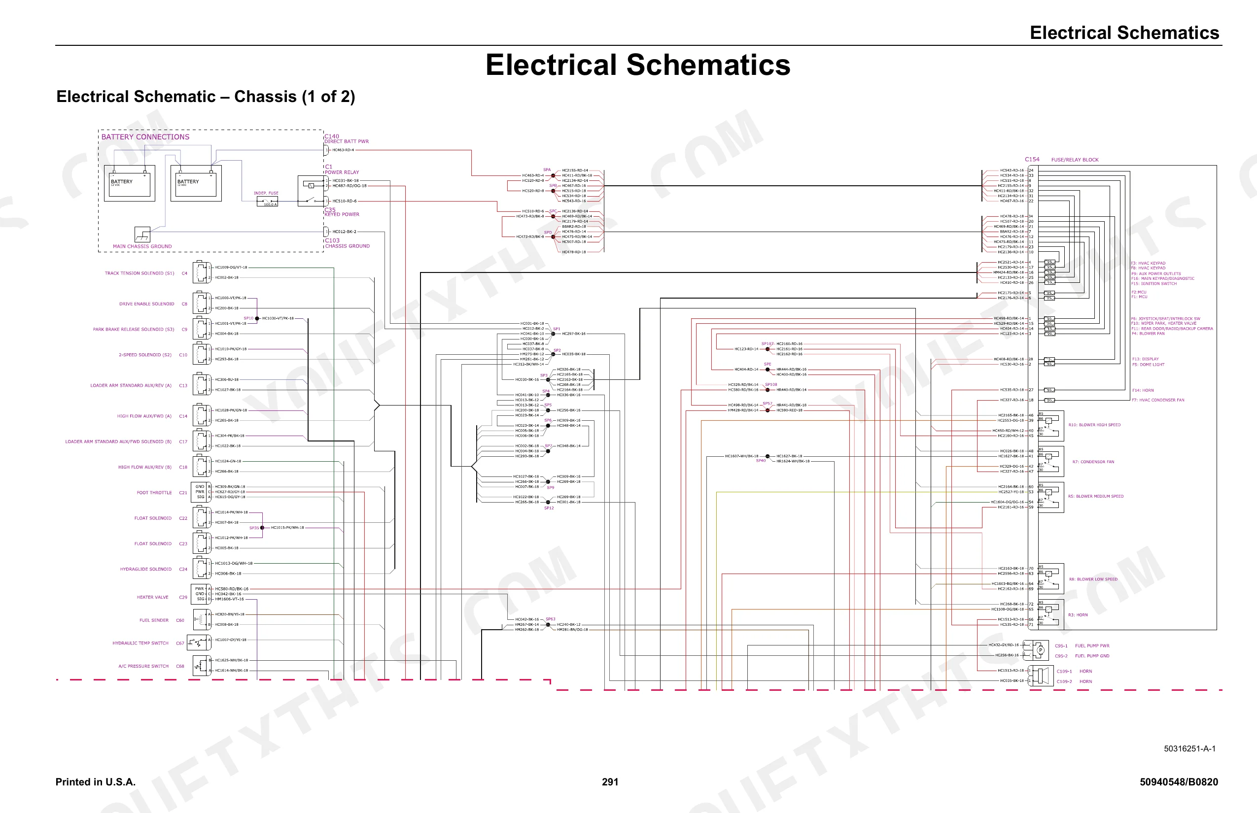
| Electrical Schematics | 293-356 | Electrical Schematic – Chassis (1 of 2), Electrical Schematic – Chassis (2 of 2), Electrical Schematic – Engine (1 of 2), Electrical Schematic – Engine (2 of 2) |
Quick Reference Specifications
| Specification | Value | Page |
|---|---|---|
| Drive Sprocket Mounting Capscrews Torque | 350 Nm (258 lb.-ft.) | p. 164 |
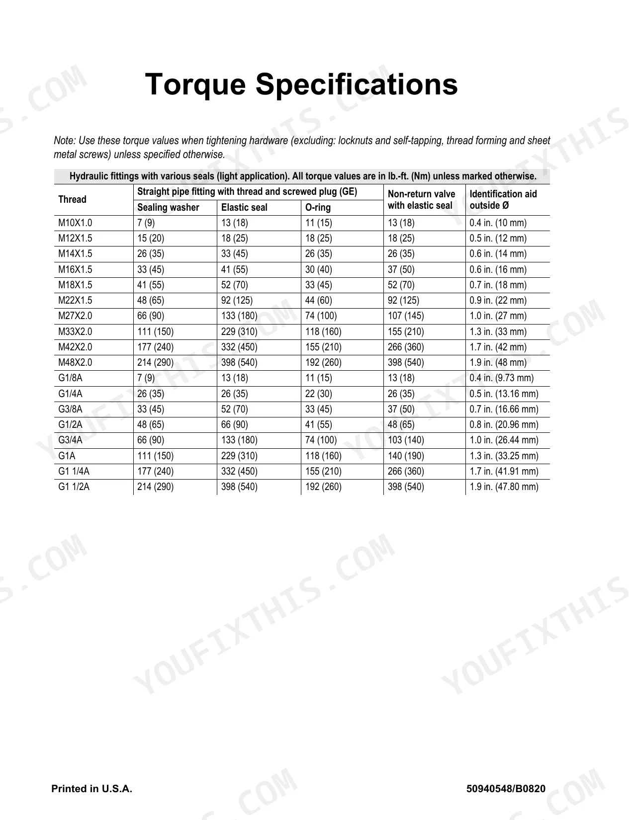
| Hydraulic Fittings Torque (Light Application Range) | 7 lb.-ft. (9 Nm) to 214 lb.-ft. (290 Nm) | p. 353 |
| Hydraulic Oil Return Filter Replacement Interval | first 50 hours, then every 500 hours or 1 year | p. 52 |
| Engine Air Filter Replacement Interval | every 250 hours of use, or every 6 months, or whenever the engine air filter restriction indicator is lit | p. 38 |
| Fuel Filter Replacement Interval | every two years, or after every 1000 hours of use (500 hours under extreme conditions) | p. 48 |
| Sprocket Wear Limit | 4mm (1/8”) of material worn | p. 167 |
| Battery Group Size | Group size 34 | p. 59 |
| Battery Cold Cranking Amps @ Temperature | 1600 CCA (combined) @ -18°C (0°F) | p. 345 |
| Fuse Rated Current (Multi-Function Display) | 5A | p. 58 |
| Fuse Rated Current (Horn) | 10A | p. 58 |
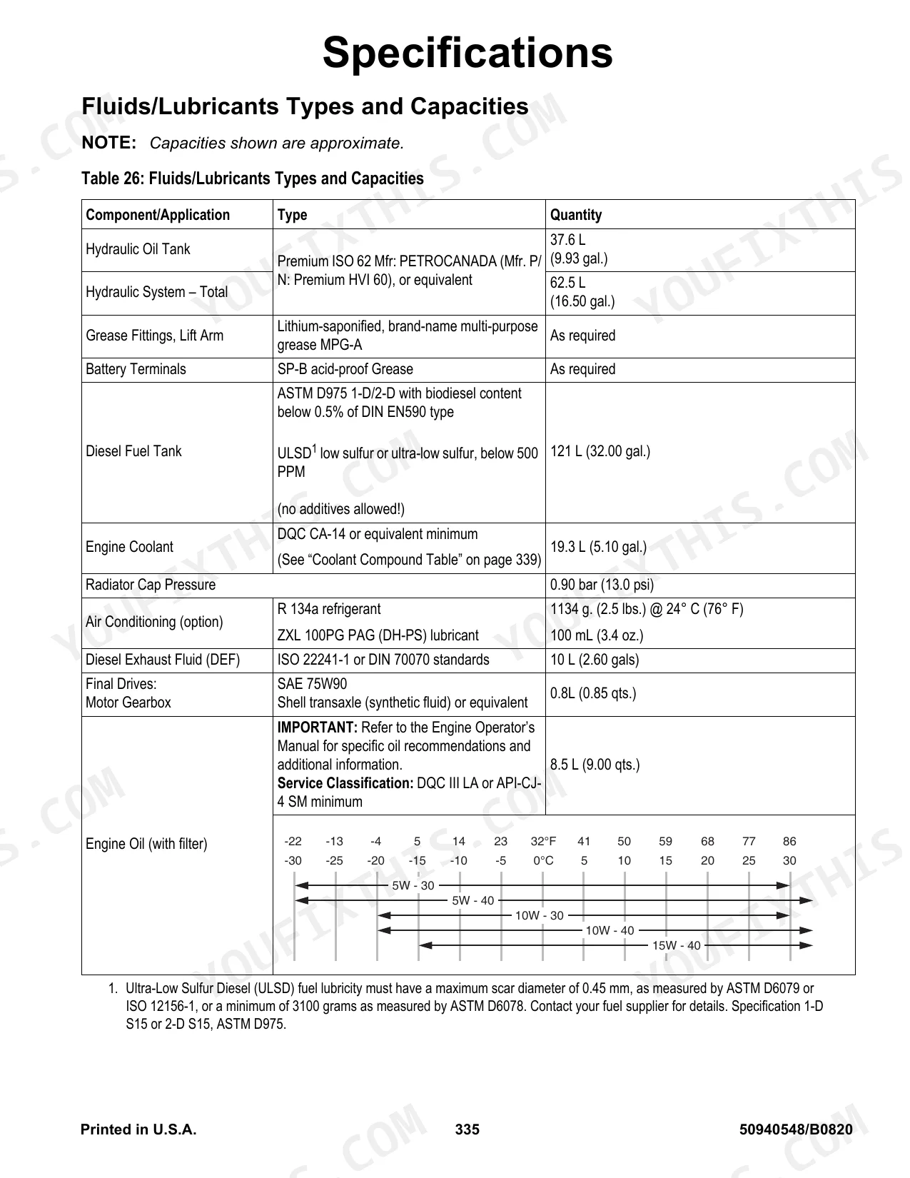
| Hydraulic Oil Tank Capacity | 37.6 L (9.93 gal.) | p. 337 |
| Diesel Fuel Tank Capacity | 121 L (32.00 gal.) | p. 337 |
Manitou Group VT320, 3200VT Common Problems This Manual Covers
Loses drive or weak travel
As a hydrostatic track loader, weak travel or one slow track usually traces to a drive motor, base pump, or control valve issue. The hydraulic schematic maps the drive motor, base pump, gear pump, and control valve for diagnosis.
Manual Section: Hydraulic Schematic p. 219Lift or tilt slow or jerky
Slow or jerky lift and tilt often comes from contaminated oil, low fluid, or a restricted filter. The hydraulic system maintenance section covers checking and changing the hydraulic oil and filter.
Manual Section: Hydraulic System Maintenance p. 49Intermittent electrical faults or dead controls
Loose connectors, damaged wiring, or a blown fuse can cause warning lights or dead controls. The electrical schematics cover the chassis, engine, seat, and cab circuits for tracing these faults.
Manual Section: Electrical Schematics p. 293Overheating or high temperature shutdown
Overheating comes from a blocked radiator or hydraulic cooler, low coolant, or a fan or belt problem. The maintenance section covers coolant level, cleaning the radiator fins, and belt service.
Manual Section: Maintenance p. 31Engine derates, hard start, or rough run
A rough running or hard starting engine often means a fuel restriction or water in the fuel. The fuel system maintenance section covers the water separator inspection and changing the water separator and fuel filter.
Manual Section: Fuel System Maintenance p. 46Track and undercarriage wear
Undercarriage wear, loose track tension, and sprocket wear are routine on a compact track loader in abrasive conditions. The maintenance section covers the inspection and service that keep the undercarriage in spec.
Manual Section: Maintenance p. 31Frequently Asked Questions
Which machine and engine does this cover?
It is the service manual for the Gehl VT320, also branded Mustang and Manitou 3200VT track loader, factory publication 50940548. It covers the machine with the TCD 3.6 L4 diesel engine across 356 pages.
Are wiring diagrams and schematics included?
Yes. The manual includes chassis and engine wire harness diagrams plus complete electrical schematics for the chassis, engine, rear door, ROPS/FOPS, and seat, along with the full hydraulic schematic. p. 285
Does it include torque specifications?
Yes. The manual gives fastener torques including the drive sprocket mounting capscrews at 350 Nm and hydraulic fitting torque ranges from 7 lb ft up to 214 lb ft. p. 353
How often should the hydraulic and fuel filters be changed?
The hydraulic return filter is replaced at the first 50 hours, then every 500 hours or 1 year, and the fuel filter every two years or 1000 hours, with full intervals in the manual. p. 52
What format is this Manitou Group VT320, 3200VT manual in?
A 356-page Service Manual in searchable PDF, ready to download the moment checkout completes. Open it on a computer, tablet, or phone with no shipping wait.
Am I able to print pages from this Manitou Group VT320, 3200VT manual?
No restrictions at all. Print individual pages, full chapters, or the entire manual. The PDF is completely unlocked.
Does this Manitou Group VT320, 3200VT Service Manual cover the hydraulic system?
Yes, this Manitou Group VT320, 3200VT Service Manual includes hydraulic system diagrams, circuit schematics, and component specifications.


Reviews
There are no reviews yet.