

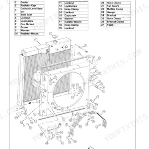
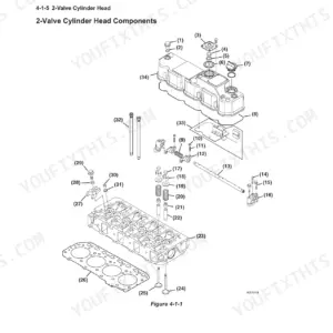
This is the Manitou service manual for the Z25 and 250Z compact excavators (form number 50940346), powered by the 3TNV80F-SXNBV diesel. Across 576 pages it covers the engine, the electrical equipment with its LCD monitor and alarms, the hydraulic system, the undercarriage, and the swing and travel drives.
You get service standards and tightening torque tables, hydraulic filter and relief-pressure data, wear limits for pins, bushings, rollers and idlers, and step-by-step removal and reinstallation for the starter motor, radiator, oil cooler, and fan belt.
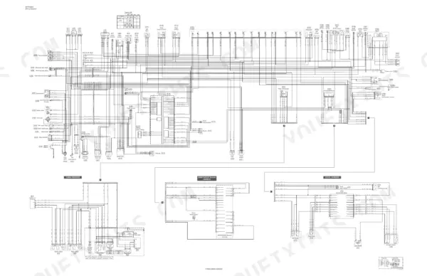
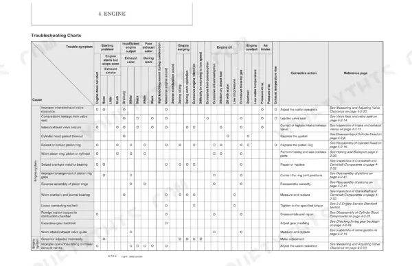
A troubleshooting quick-reference table helps trace weak hydraulics, travel problems, and starting faults to a cause, and the appendix carries the wiring diagram. Owners and independent shops can diagnose and repair the Z25 and 250Z with factory numbers instead of guesswork. It is delivered as a downloadable PDF for any device or the shop printer.
What's Inside This Manual
| System | Pages | Key Topics |
|---|---|---|
| General Cautions for Maintenance Work | 9-20 | Correct Work, Safety Precautions, Preparations, Cautions for Disassembly and Reassembly, Cautions for Removal and Installation of Hydraulic Equipment |
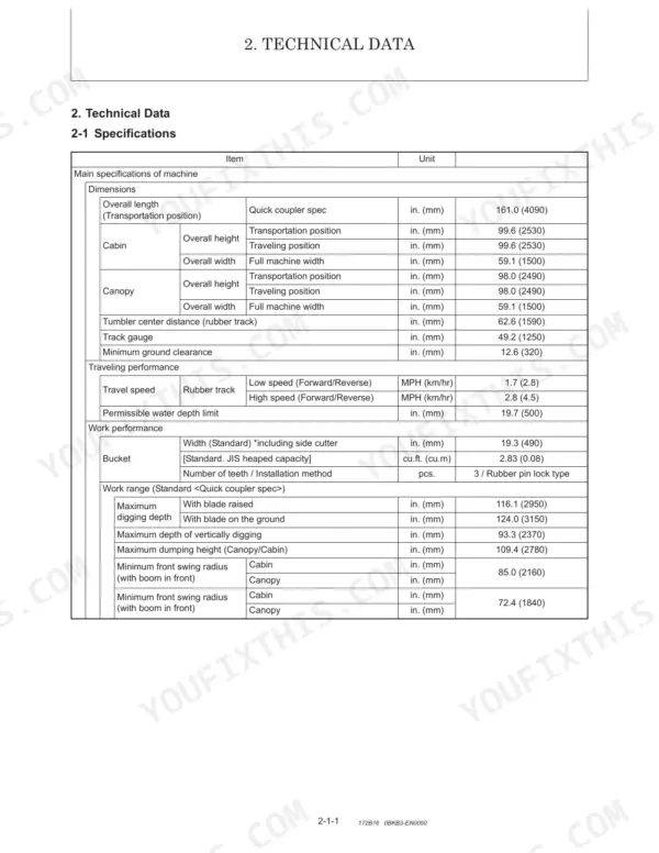
| Technical Data | 21-48 | Specifications, Outline Drawing and Working Area, Weight List of Main Parts, Lifting Capacity List, Specifications for Attachment, Periodic Inspection and Servicing, Fuel |
| Service Standards | 49-78 | Machine Performance, Undercarriage (Rubber Track Specifications, Common Specifications of Rubber Crawlers), Controls, Hydraulic Equipment (Hydraulic Cylinders) |
| Engine | 79-218 | Before You Begin Servicing, Introduction, Special Service Tools, Measuring Instruments, Cylinder Head, Disassembly of Rocker Arm Assembly, Measuring and Adjusting Valve Clearance |
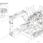
| Electric System | 219-246 | Electric Equipment of Machine (Parts Layout of Electrical Equipment, Lcd Monitor and Alarm Systems), Circuit Description of Engine Start and Stop (Battery Charge) |
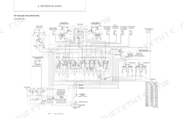
| Hydraulic System | 247-456 | Outline (Control Valve Operation, Additional Operation of Control Valve) |
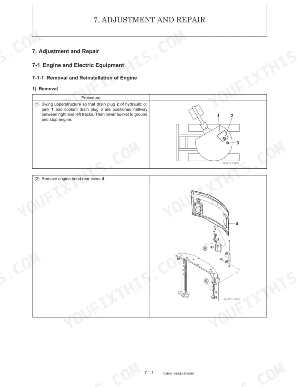
| Adjustment and Repair | 457-556 | Engine and Electric Equipment (Removal Reinstallation: Starter Motor, Radiator and Oil Cooler, Fan Belt) |
| Troubleshooting | 557-572 | Quick Reference Table for Troubleshooting |
| Appendix Wiring Diagram | 573-575 | Wiring Diagram, Cabin Harness, SmartAssist-Remote Harness, Decel Harness |
| Disclaimer | 576 | Warning, Operator's Manual Usage, Do Not Remove From the Machine, California Proposition 65 Warnings |
Quick Reference Specifications
| Specification | Value | Page |
|---|---|---|
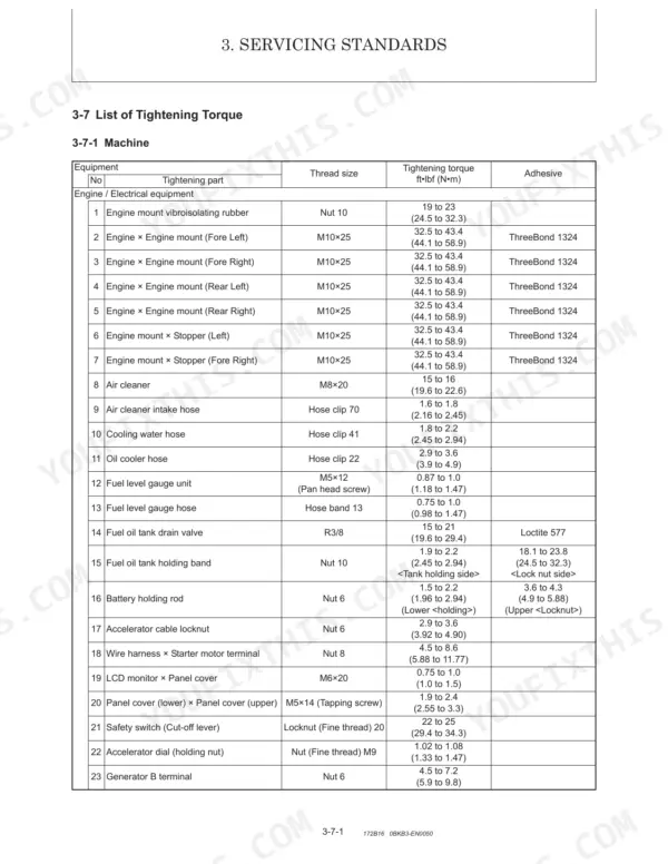
| Wheel nuts torque | Not specified directly; general bolt/nut tightening torques are provided based on thread size and strength classification in Section 3-7-3. | p. 72 |
| Suction filter filtration area | 108 sq.in. (697 sq.cm) | p. 27 |
| Suction filter filtration accuracy | 150 u | p. 27 |
| Hydraulic hose clip 60 tightening torque | 3.7 to 4.3 ft·lbf (4.5 to 5.9 N·m) | p. 68 |
| Hydraulic hose clip 13 tightening torque | 1.9 to 2.4 ft·lbf (2.5 to 3.4 N·m) | p. 68 |
| Oil seal capacity to resist pressure (pump housing) | 42.7 PSI (0.3 MPa) | p. 289 |
| General seal replacement rule | Replace all removed seals and O-rings with new ones during reassembly. | p. 317 |
| General allowable clearance for pin and bore of bush or hole (Front Attachments) | 0.04 in. (1.0 mm) | p. 64 |
| Wrist pin bushing bore standard diameter | 0.8671 to 0.8676 in. (22.025 to 22.038 mm) | p. 58 |
| Bucket fulcrum pin diameter (standard) | Ø1.50 (38) in. (mm) | p. 64 |
| Bucket 'link A' pin diameter (standard) | Ø1.50 (38) in. (mm) | p. 64 |
| Swing bearing to track frame tightening torque | 87 to 94 ft·lbf (117.7 to 127.5 N·m) | p. 67 |