

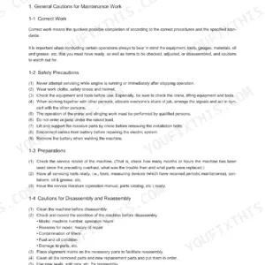
This is the factory service manual for the Manitou America Z17 GEN:2 and 170Z NXT2 compact excavator, covering machines with serial number 09714 and after. It runs 398 pages and documents the Yanmar 3TNV74F-SPBV diesel engine along with the machine's hydraulic system, electrical equipment, and undercarriage.
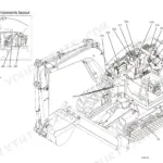
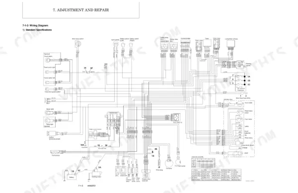
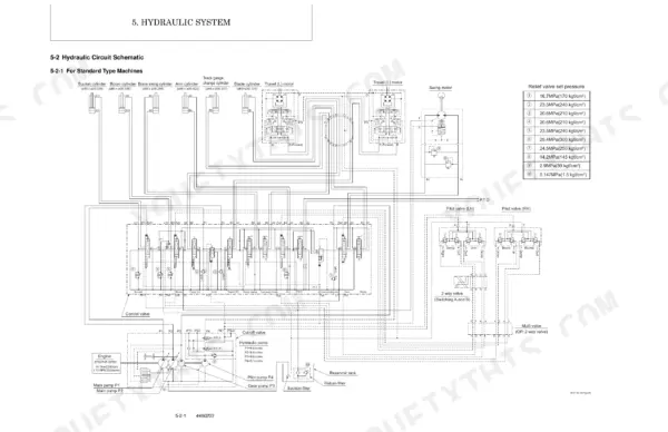
Inside you get exploded engine views, hydraulic circuit schematics and pressure settings, wiring diagrams, torque values, and step by step removal and reinstallation procedures for the hydraulic pump, control valve, swing motor, and swivel joint. Troubleshooting tables and periodic servicing lists round out the coverage.
Owners, independent mechanics, and restorers can use it to diagnose starting faults, reset hydraulic relief pressures, service the engine, and rebuild hydraulic components without guesswork. It is a searchable PDF you can download instantly and print any page you need at the bench.
What's Inside This Manual
| System | Pages | Key Topics |
|---|---|---|
| General Cautions for Maintenance Work | 7-20 | Correct Work, Safety Precautions, Preparations, Cautions for Disassembly and Reassembly, Cautions for Removal and Installation of Hydraulic Equipment |
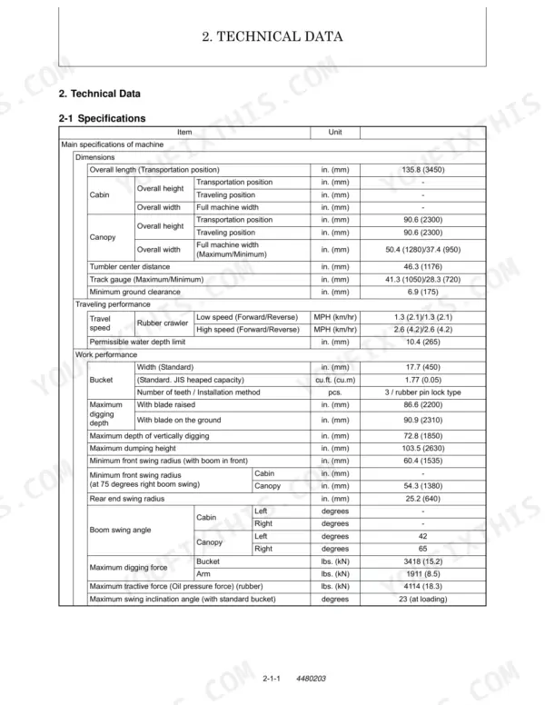
| Technical Data | 21-34 | Specifications, Outline Drawing and Working Area, Weight List of Main Parts, Lifting Capacity List |
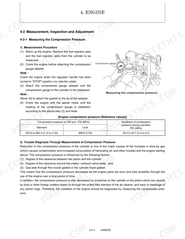
| Engine | 57-96 | Measurement |
| Hydraulic System | 97-132 | Outline (Control Valve Operation, Additional Operation of Control Valve), Hydraulic Circuit Schematic (for Standard Type Machines) |
| Hydraulic Equipment | 133-256 | Removal and Reinstallation of Hydraulic Pump, Removal and Reinstallation of Control Valve, Removal and Reinstallation of Swing Motor, Removal and Reinstallation of Swivel Joint |
| Adjustment and Repair | 257-346 | Electric Equipment of Machine (Parts Layout of Electrical Equipment, Monitor and Alarm Systems, Wiring Diagram, Circuit Description of Engine Start and Stop, And Battery Charging, Removal and Reinstallation of Engine, Removal and Reinstallation of Starter Motor, Removal and Reinstallation of Fuel Injection Pump, Removal and Reinstallation of Fuel Tank, Removal and Reinstallation of Radiator) |
| Periodic Inspection and Servicing | 347-350 | List of Periodic Inspection and Servicing |
| Fuel, Lube Oil and Grease Recommended | 351-354 | List of Fuel, Lube Oil and Grease Recommended, Item, Type, Part Be Refilled, Oil Type, Recommendations Based on Temperature Ranges, Prescribed Amount of Oil |
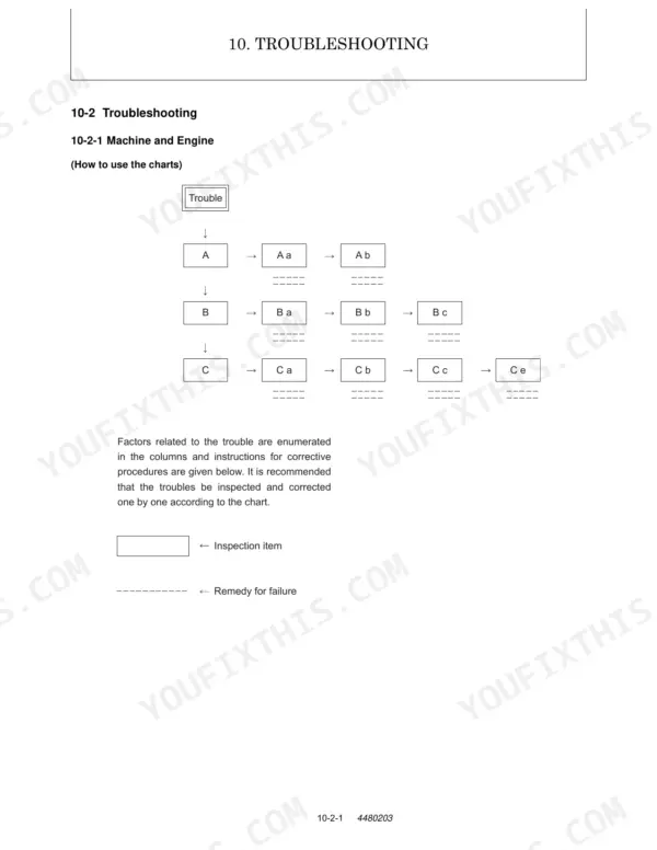
| Troubleshooting | 355-392 | Machine and Engine, Low Output, Overheating |
| Reference Data | 393-398 | Specifications for Attachment |
Quick Reference Specifications
| Specification | Value | Page |
|---|---|---|
| Main relief valve P1 set pressure | 2987 PSI (20.6 MPa) | p. 129 |
| Main relief valve P2 set pressure | 2987 PSI (20.6 MPa) | p. 129 |
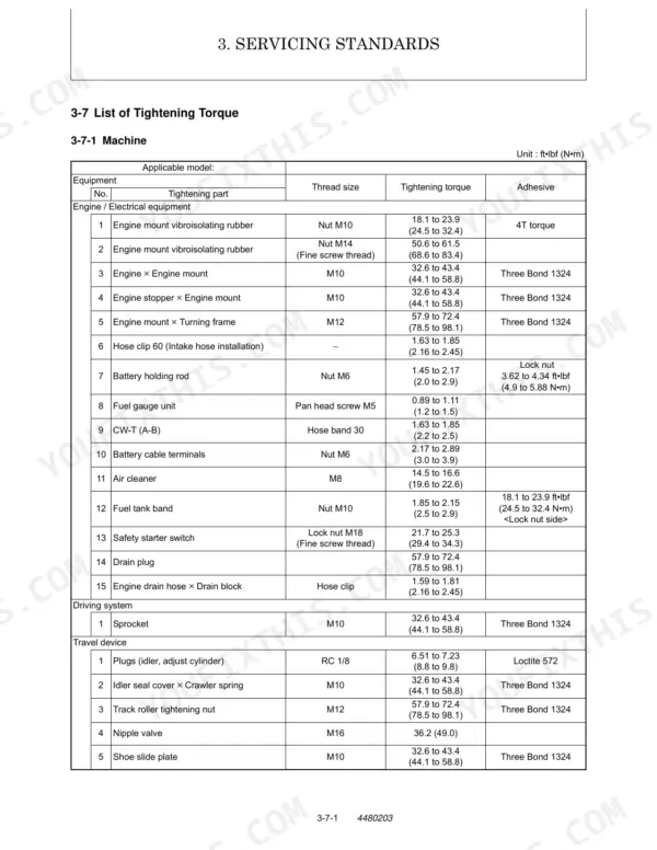
| Track roller tightening nut (M12) tightening torque | 57.9 to 72.3 ft•lbf (78.5 to 98.1 N•m) | p. 51 |
| Battery type | 65B24L | p. 29 |
| Battery voltage - 5 hrs rate capacity | 12-40 V-Ah | p. 29 |
| Starter motor model | RA1.4 | p. 29 |
| Alternator model | GP9191 | p. 93 |
| Alternator nominal output | 20 A | p. 93 |
| Tightening torque for parallel pipe thread (1/8) | 10.1 to 12.3 ft•lbf (13.7 to 16.7 N•m) | p. 55 |
| Tightening torque for taper pipe thread (1/8) | 5.09 to 6.50 ft•lbf (6.9 to 8.8 N•m) | p. 55 |
| Intake valve oil clearance (wear limit) | 0.006 in. (0.15 mm) | p. 41 |