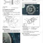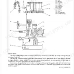
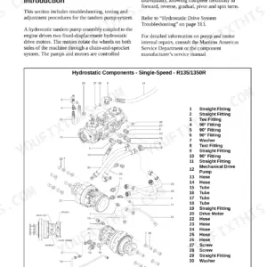
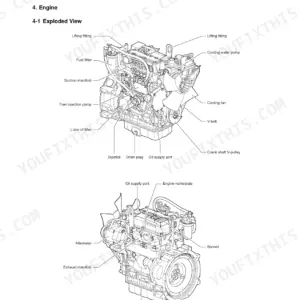
This service manual covers the compact track loaders sold as Gehl RT185, RT215, and RT255 and as Mustang and Manitou 1850RT, 2150RT, and 2550RT. It runs 316 pages and supports machines built with the Yanmar 4TNV98C-NMSL, Yanmar 4TNV98-ZNMS, and Deutz TD 3.6 L4 engines.
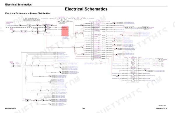
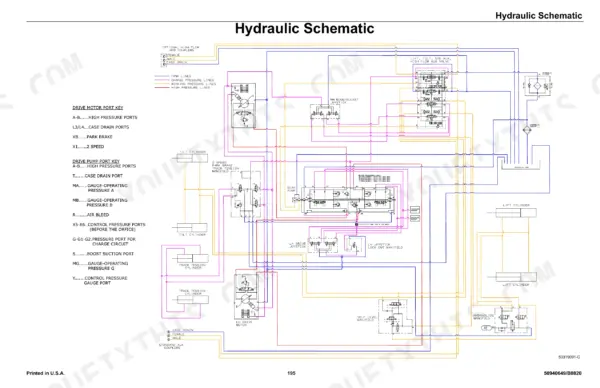
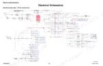
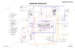
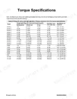
The manual includes full hydraulic schematics, chassis and engine wire harness diagrams, and electrical schematics for power distribution, the chassis, the ROPS and FOPS structure, and the operator's seat, alongside maintenance intervals, fluid capacities, and torque specifications.
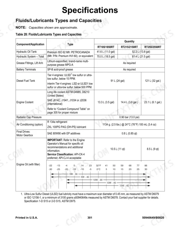
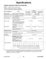
Owners, fleet techs, and independent mechanics can use it to trace hydraulic and electrical circuits, plan filter and fluid service, and torque drivetrain hardware correctly. Hydraulic system capacity ranges from 70.0 L (18.5 gal) on the RT185 to 81.4 L (21.5 gal) on the larger models. It is a searchable PDF for instant download and printing.
What's Inside This Manitou Group RT-Series Track Loaders Manual
| System | Pages | Key Topics |
|---|---|---|
| Safety | 9-28 | Safety Symbol and Signal Words, Mandatory Safety Shutdown Procedure, Applications with Load-Handling Devices, Parking the Machine, Electrical Energy, Maintenance and Service Safety Practices, Battery Hazards |
| Introduction | 29-34 | Contents and Use of This Manual, Machine Orientation, Component Identification, Machine Model and Serial Number Locations, ROPS/FOPS Certification Label, Indicator and Operation Symbols, Machine Controls and Operation |
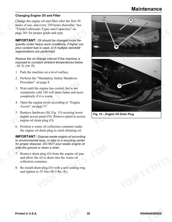
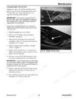
| Maintenance | 35-68 | Maintenance Schedule, Checks, Cleaning and Inspection, Leakage Check, Lubrication and Filter Changes, Functional Check, Engine Maintenance, Engine Air Filters |
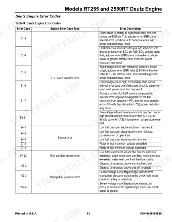
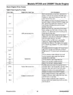
| Models RT255 and 2550RT Deutz Engine | 69-100 | General Information, Deutz SerDia Connection, Engine Access, Engine Maintenance, Deutz Engine Removal/Installation, Fuel System Maintenance, Engine Troubleshooting |
| Models RT215, RT185, 2100RT, and 1850RT Yanmar Engine | 101-132 | General Information, Yanmar SmartAssist Connection, Engine Access, Engine Maintenance, Yanmar Engine Removal/Installation, Fuel System Maintenance, Engine Troubleshooting |
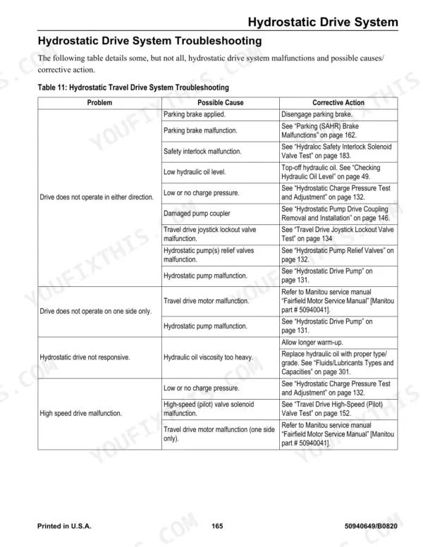
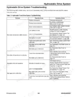
| Hydrostatic Drive System | 133-168 | General Information, General Hydraulic Service Notes, Hydraulic Oil Analysis, Hydrostatic Drive Pump, Hydrostatic Pump Relief Valves, Travel Drive Troubleshooting, Neutral Centering Check/Adjustment |
| Work Hydraulics | 169-196 | General Information, General Hydraulic Service Notes, Hydraulic Oil Analysis, Hydraulic Hoses/Tubes, Seals, Main Pressure Test and Adjustment, Hydraulic Gear Pump |
| Hydraulic Schematic | 197-252 | Control Valve, Track Tension Cylinder, Travel Motor, Lift Cylinder, Tilt Cylinder, Hydraglide Manifold |
| Wire Harness Diagrams | 253-263 | Chassis Wire Harness Diagram - RT255 and 2550RT (Page 1 of 2), Chassis Wire Harness Diagram - RT255 and 2550RT (Page 2 of 2), Chassis Wire Harness Diagram - RT185, RT215, 1850RT |
| Electrical Schematics | 264-316 |
Quick Reference Specifications
| Specification | Value | Page |
|---|---|---|
| RT215, RT185, 2100RT, and 1850RT | ||
| Hydrostatic pump to engine flywheel housing mounting screws torque | 102 Nm (75 lb.-ft.) | p. 113 |
| Engine mounting hardware torque | 203 Nm (150 lb.-ft.) | p. 113 |
| All Models | ||
| Hydraulic oil return filter replacement interval | After first 50 hours; every 500 hours thereafter | p. 38 |
| Hydraulic oil filter installation torque | 3/4 rotation past the point where the gasket contacts the filter head | p. 50 |
| Fuel filter replacement interval | annually, or after every 500 hours of use | p. 49 |
| Engine air filters replacement interval | every 250 hours of use, or every 6 months, or whenever the engine air filter restriction indicator on the indicator panel is lit | p. 43 |
| Inner air filter element replacement interval | every third time the outer element is replaced, unless the outer element is damaged or the inner element is visibly dirty | p. 43 |
| Hydraulic hoses replacement interval | every six years from the date of manufacture | p. 54 |
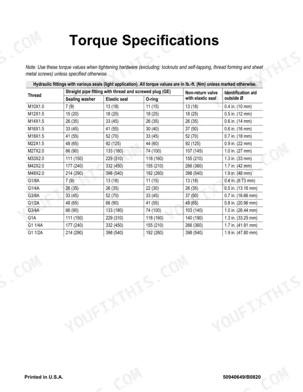
| Hydraulic tubing nuts tightening torque | 1/4 to 1/2 turn after reaching a sharp torque rise point | p. 170 |
| Sprocket wear limit | 4mm (1/8”) of material worn from any point along the sprocket tooth profile | p. 158 |
| Rear idler mounting screws torque | 570 Nm (420 lb.-ft.) | p. 154 |
| RT255/2550RT | ||
| Fuel filters (primary and water separator) replacement interval | Every 1000 hours; 500 hours under extreme conditions | p. 38 |
Manitou Group RT-Series Track Loaders Common Problems This Manual Covers
Weak or intermittent hydraulic functions
Hydraulic functions that drop off under load or turn intermittent can come from pump wear, a valve fault, or a bad sensor in the control circuit. The Hydraulic Schematic section maps the control valve, lift and tilt cylinders, and Hydraglide manifold so the circuit can be traced.
Manual Section: Hydraulic Schematic p. 197Drive or track power loss
A drive system that stalls, jerks, or loses power on one track often points to the travel motor or track tension circuit. The Hydraulic Schematic section shows the travel motor and track tension cylinder to help locate the problem.
Manual Section: Hydraulic Schematic p. 197No-start or crank but no run
A machine that will not start or cranks without running can be a battery, starter circuit, safety interlock, or controller wiring fault. The Electrical Schematics section covers power distribution and the chassis circuits used to isolate the cause.
Manual Section: Electrical Schematics p. 264Intermittent electrical faults
Flickering functions or dead circuits frequently trace to a damaged harness or connector. The Wire Harness Diagrams section gives the chassis and engine wire harness routing for each engine variant to check continuity and pin assignments.
Manual Section: Wire Harness Diagrams p. 253Auxiliary hydraulics respond erratically
Erratic or reduced auxiliary response usually means a pilot control fault, solenoid valve issue, or contamination. The Hydraulic Schematic section shows the manifold and control valve feeding the auxiliary circuit.
Manual Section: Hydraulic Schematic p. 197Charging or lighting problems
Weak charging, warning lights, or dead accessories point to the power distribution and chassis wiring. The Electrical Schematics section covers power distribution, the chassis, and the road lights circuits for these loaders.
Manual Section: Electrical Schematics p. 264Frequently Asked Questions
Which machines and engines does this manual cover?
It covers the Gehl RT185, RT215, and RT255 and the Mustang and Manitou 1850RT, 2150RT, and 2550RT compact track loaders, built with Yanmar 4TNV98C-NMSL, Yanmar 4TNV98-ZNMS, and Deutz TD 3.6 L4 engines.
Does it include wiring diagrams?
Yes. The Electrical Schematics section covers power distribution, the chassis, the ROPS and FOPS structure, the operator's seat, and per-engine circuits, backed by the Wire Harness Diagrams section. p. 264
Does it cover the hydraulic circuits?
Yes. The Hydraulic Schematic section maps the control valve, travel motor, lift and tilt cylinders, track tension cylinder, and Hydraglide manifold. p. 197
Is this a single manual for all six models?
Yes. One 316-page service manual covers all six rebadged models, so the same procedures, diagrams, and specifications apply whether the machine wears Gehl, Mustang, or Manitou branding.
How will I receive this Manitou Group RT185 & variants Service Manual?
This is a 316-page searchable PDF, ready to download the moment you order. It opens on any device, so you can pull it up on your phone right at the machine. No shipping, no waiting.
Am I able to print pages from this Manitou Group RT185 & variants manual?
Yes. Many buyers print one chapter at a time for their own shop and keep the rest on a tablet.
Are there wiring harness diagrams in this Manitou Group RT185 & variants manual?
Yes, this Manitou Group RT185 & variants Service Manual includes complete electrical wiring diagrams, wire routing, and connector pinouts.