

Part of the Kubota Repair Manuals.
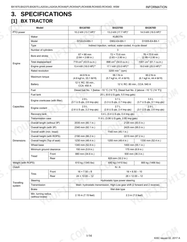
This is the Kubota Workshop Manual for the BX1870, BX2370, and BX2670 sub-compact tractors, the RCK48-18BX, RCK54-23BX, RCK60B-23BX, RCK48P-18BX, RCK54P-23BX, RCK54D-26BX, and RCK60D-26BX mower decks, and the LA203A and LA243A front loaders. The tractors run the D722-E4-BX-1, D902-E4-BX-1, and D1005-E4-BX-1 diesel engines.
This 417 page English PDF is the service-level manual, organized into Information, General, and system chapters for the engine, transaxle, front axle, steering, hydraulics, electrical, mower, and front loader. Each chapter gives mechanism, checking, disassembly, servicing specifications, and tightening torques.
Independent mechanics and serious owners can use it to diagnose faults, rebuild components, set relief pressures, and torque fasteners to spec across the whole machine. Download it, keep it on the bench, and print the sections you need.
What's Inside This Manual
| System | Pages | Key Topics |
|---|---|---|
| G General | Identification (Tractor Identification, Mower Identification, Front Loader Identification) | |
| Engine | Lubricating System, Cooling System, Fuel System, Checking | |
| Transaxle | Traveling System (Hydrostatic Transmission, Range Gear Shift Section, Front Wheel Drive Section, Differential Gear Section, Brake Section) | |
| Front Axle | Front Wheel Alignment, Structure, Checking | |
| Steering | Steering Controller, Steering Cylinder, Hydraulic Circuit, Checking | |
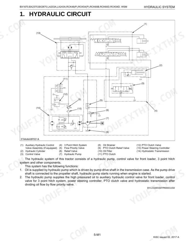
| Hydraulic System | Hydraulic Pump, Control Valve, Flow Priority Valve, Relief Valve, Hydraulic Cylinder, Hydraulic Block Type Outlet, Mower Linkage | |
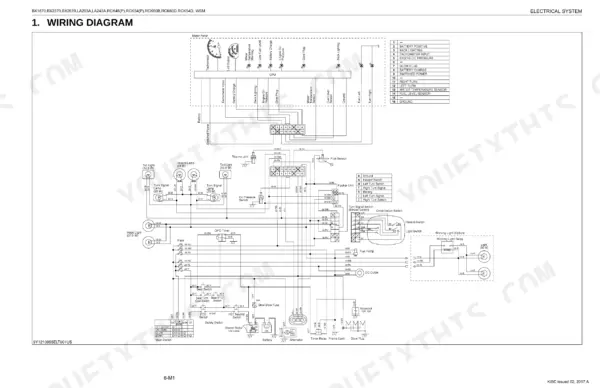
| Electrical System | Wiring Diagram, Starting System (Main Switch Position, Safety Switch, Operator Presence Control), Charging System (Electrical Circuit, Ic Regulator), Lighting System | |
| Mower | Power Transmission, Lifting Mechanism, Self-Balancer System, Setting Up Mower (Rck48-18Bx, Rck54-23Bx, Rck60B-23Bx, Rck48P-18Bx, And Rck54P-23Bx, Rck54D-26Bx, Rck60D-26Bx) | |
| Front Loader | Hydraulic Circuit Schematic, Control Valve Assembly, Boom Cylinder and Bucket Cylinder |
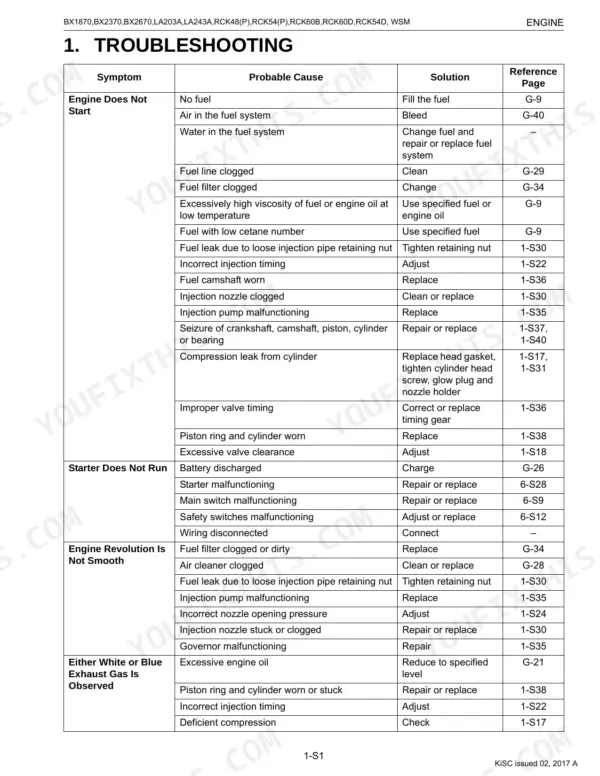
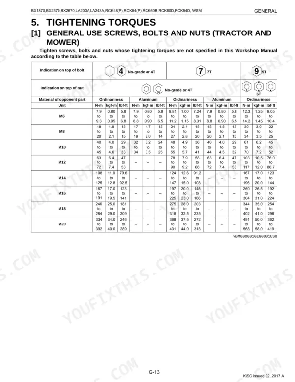
Every system also includes tightening torques, disassembling and servicing, servicing specifications, and troubleshooting.
Documents This Manual Refers To
The manufacturer cites these publications by number. We carry them:
Quick Reference Specifications
| Specification | Value | Page |
|---|---|---|
| BX1870D, BX2370D, BX2670D | ||
| Front wheel mounting screws torque | 149.2 to 179.0 N·m (15.2 to 18.3 kgf·m, 110 to 132 lbf·ft) | p. 54 |
| Rear wheel mounting screws torque | 108.5 to 130.2 N·m (11.1 to 13.3 kgf·m, 80 to 96 lbf·ft) | p. 54 |
| RCK48-18BX | ||
| Mower link clearance (between stopper and rear link) | 0 to 0.5 mm (0 to 0.01 in.) | p. 385 |
| RCK48-18BX, RCK54-23BX, RCK60B-23BX, RCK48P-18BX, RCK54P-23BX | ||
| Anti-scalp rollers to ground clearance | 6 to 13 mm (0.25 to 0.5 in.) | p. 386 |
| RCK54D-26BX | ||
| Mower blade screw torque | 103 to 117 N·m (10.5 to 12.0 kgf·m, 76.0 to 86.7 lbf·ft) | p. 375 |
| Gear box mounting screw torque | 78 to 90 N·m (7.9 to 9.2 kgf·m, 58 to 66 lbf·ft) | p. 375 |
| All Models | ||
| Relief valve setting pressure (Oil temperature at 45 to 55 °C (113 to 131 °F)) | 12.3 to 12.7 MPa (125 to 130 kgf/cm², 1780 to 1840 psi) | p. 303 |
| Air cleaner element replacement interval | Every 1000 hours or every 1 year whichever comes first | p. 57 |
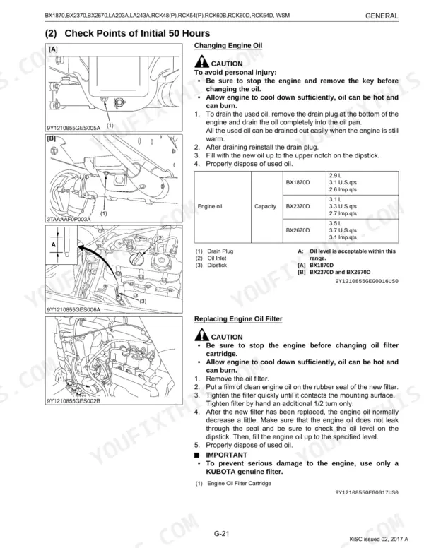
| Engine oil filter replacement interval | every 200 Hr | p. 46 |
| Transmission oil filter replacement interval | every 200 Hr | p. 46 |
| Fuel filter element replacement interval | every 400 Hr | p. 46 |
| Radiator screen cleaning interval | Daily | p. 49 |