


This is the factory Mustang 2064 and 2074 Skid Steer Loader Service Manual, part number 000-88025, a 130 page PDF covering machines built from 2002 to 2004 with the Isuzu 4JB1 diesel engine.It covers the loader end to end: model specifications, safety systems and interlocks, general information with the maintenance chart and torque procedures, steering controls, the hydraulic system with leak-down tests and cylinder repair, the hydrostatic drive, chain case and final drive, engine service, the electrical system with interlock and starter circuits, and accessories. Relief pressures, charge pressure, and fastener torque values are called out where they differ between the 2064 and 2074.From a soft hydrostatic drive to a chain case rebuild, this manual gives you the diagnostics and specifications to fix the machine yourself. It is a searchable PDF you can download now and print any page.
What's Inside This Mustang 2064, 2074 Manual
| System | Pages | Key Topics |
|---|---|---|
| Introduction | 3-4 | Manual Purpose And Scope, Operator Safety And Equipment, Serial Number For Service Information, Serial Number System, 2064 Serial Number Format, 2074 Serial Number Format |
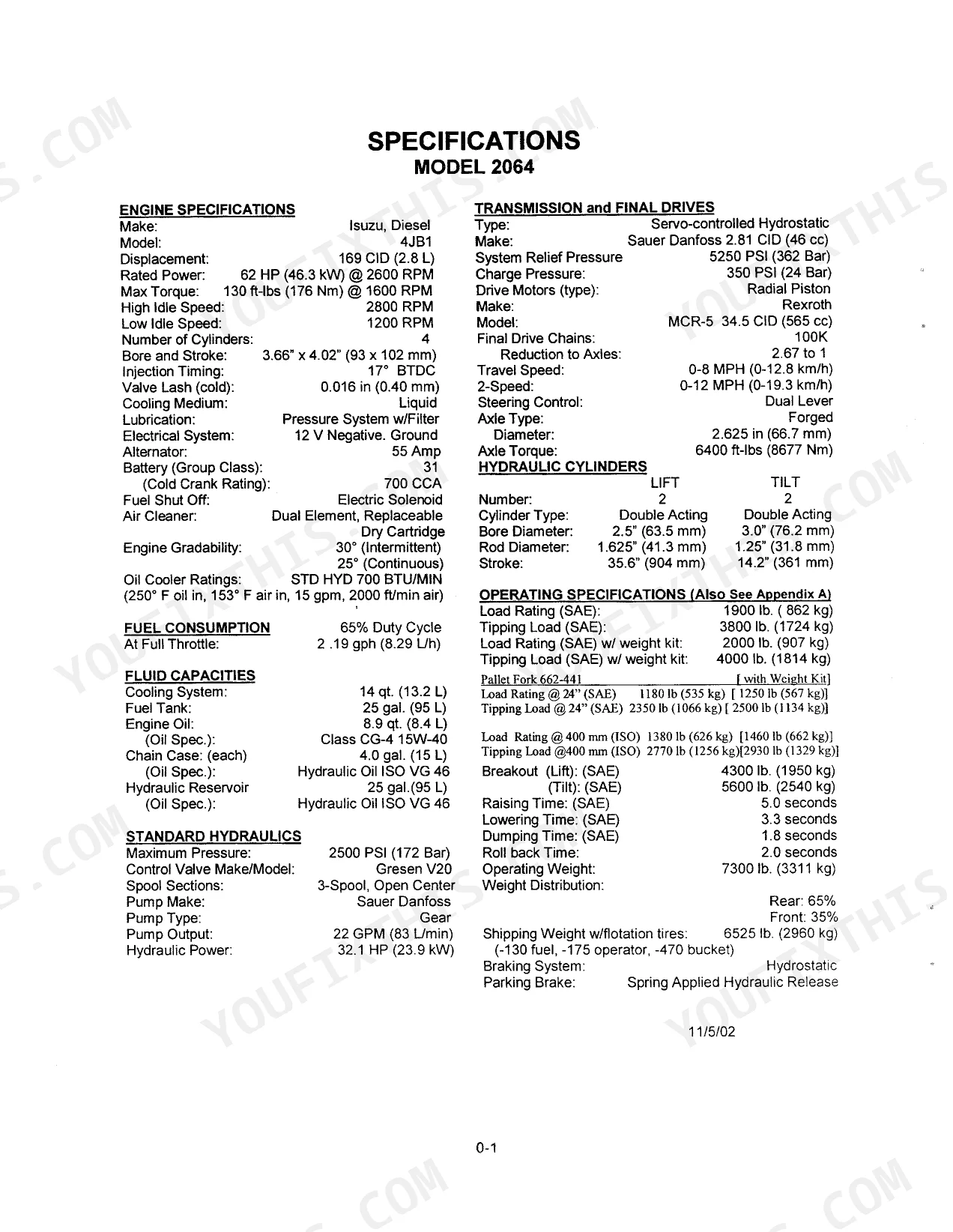
| Specifications | 5-8 | Specifications 2064, Specifications 2074 |
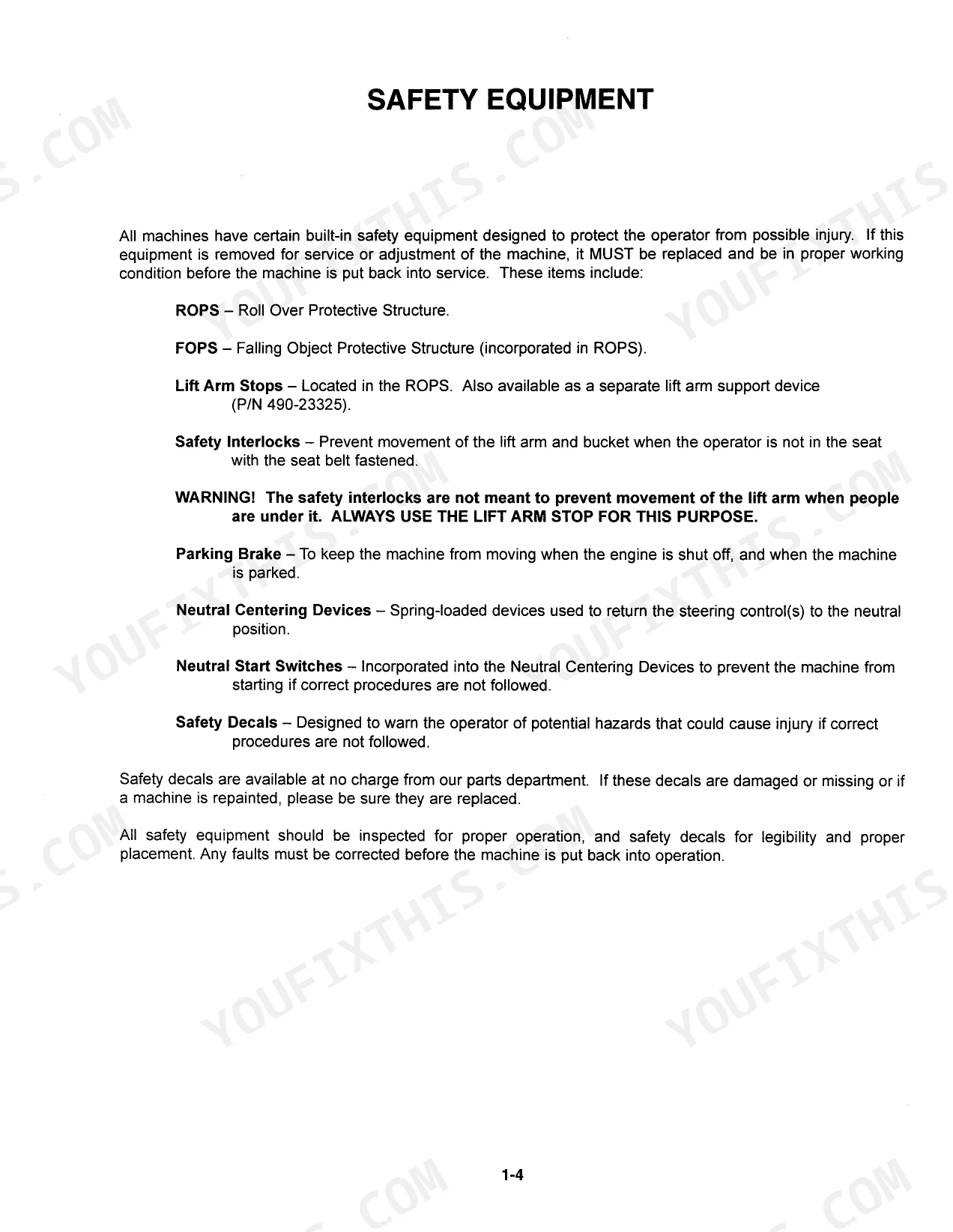
| Safety | 9-25 | General Precautions, Safety Equipment, Lift Arm Stops, Roll Over Protective Structure - Removal and Installation, Safety Interlocks, Lift Arm Bypass Switch, Parking Brake |
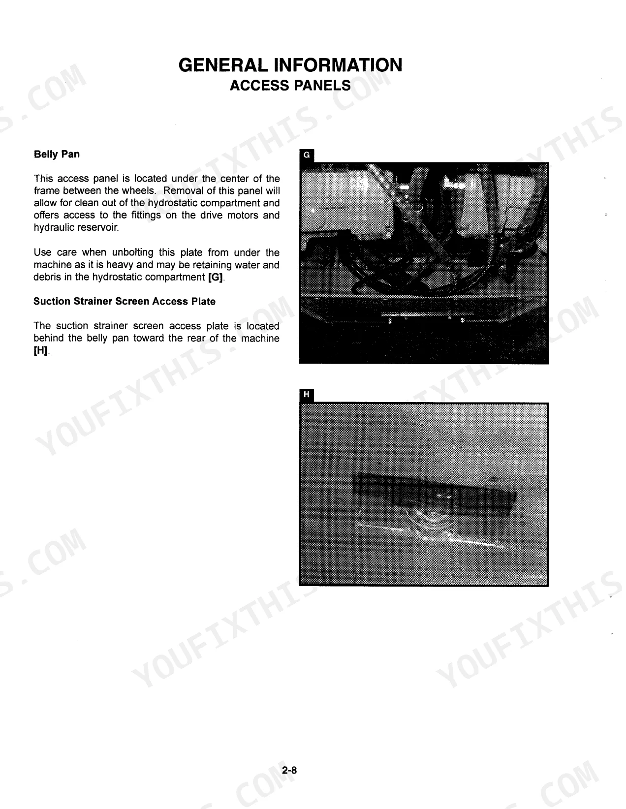
| General Information | 26-38 | System Contamination Control, Hydraulic Fluid, Maintenance Chart, Pre-Delivery Check List, 50 Hour Check List, Access Panels, Torque Specifications and Procedures, Special Tools |
| Steering Controls | 39-44 | Troubleshooting, Neutral Centering Device - Adjustments, Steering Controls - Dual Lever |
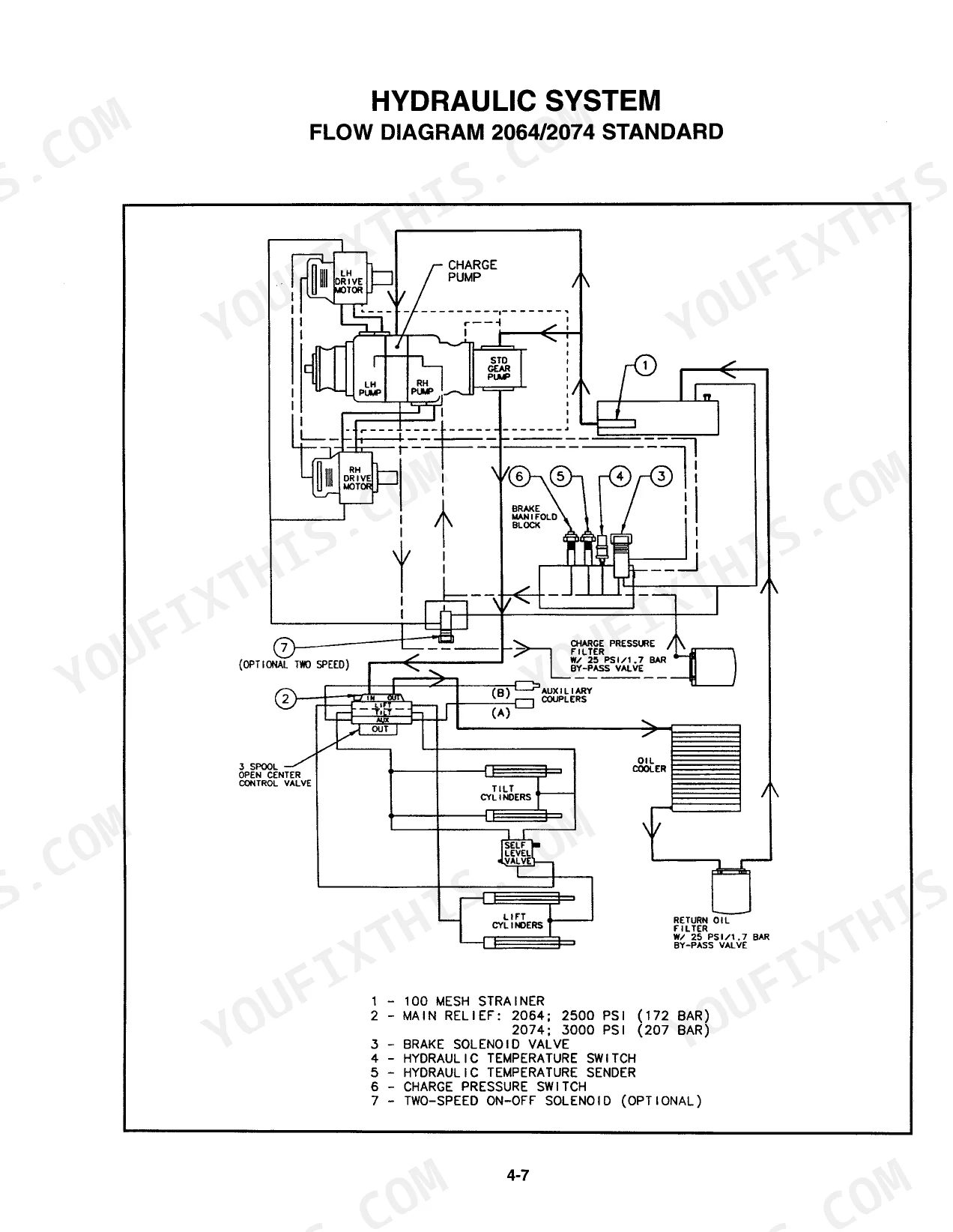
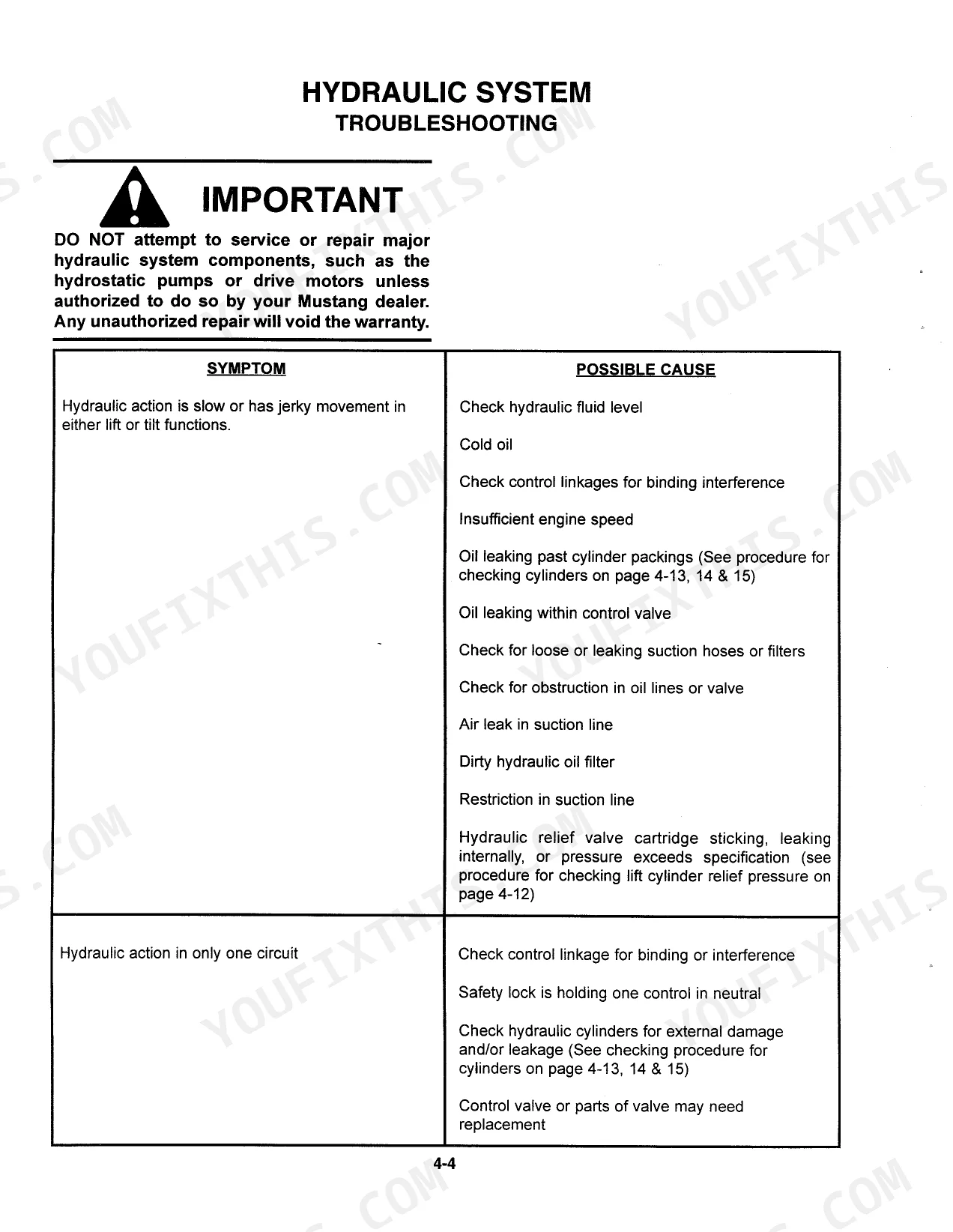
| Hydraulic System | 45-71 | Hi-Flow, Troubleshooting, Flow Diagram, Controls, Lift Circuit Leak-Down Test, Tilt Circuit Leak-Down Test, Hydraulic Cylinder Testing, Hydraulic Cylinder Service and Repair |
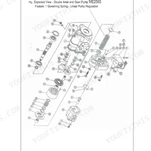
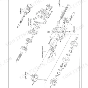
| Hydrostatic Drive System | 72-89 | Troubleshooting, Flow Diagram, Flow Schematic |
| Chain Case | 90-97 | Explanation, Axle Housing R & I, Axle Housing - Assembly, Axle Assembly, Drive Chain & Sprocket - R & I, Drive Chain & Sprocket Chain Case Assembly, Troubleshooting |
| Engine | 98-110 | Troubleshooting, Engine / Hydrostatic Pump – Removal and Installation, Cooling System (Troubleshooting), Fuel System, Injection Timing, Air Cleaner, Turbo Charger |
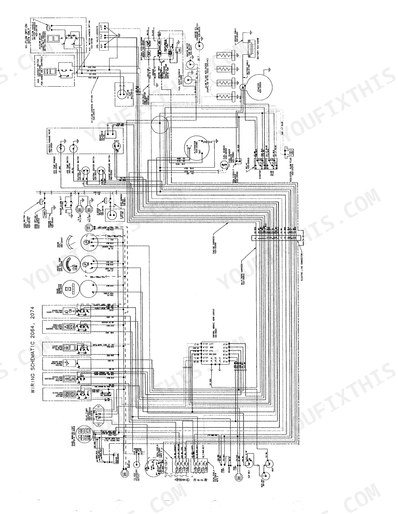
| Electrical System | 111-125 | Instrument Panel, Interlock Circuit, Interlock Circuit Wiring Diagram, Control Module Tests, Brake Circuit Wiring Diagram, Starter Circuit Wiring Diagram |
| Accessories | 126-130 | Cab Door, Cabin Heater, Accessory Outlet / Int. Light / Beacon, Backup Alarm, Wiring Schematic, Auto Shutdown |
Quick Reference Specifications
| Specification | Value | Page |
|---|---|---|
| All Models | ||
| J.I.C. (SAE 37° flare) Fittings Torque - 1/4" Hose & Tubing Diameter | 8-12 ft-lbs | p. 35 |
| J.I.C. (SAE 37° flare) Fittings Torque - 5/16" Hose & Tubing Diameter | 12-15 ft-lbs | p. 35 |
| J.I.C. (SAE 37° flare) Fittings Torque - 3/8" Hose & Tubing Diameter | 15-25 ft-lbs | p. 35 |
| J.I.C. (SAE 37° flare) Fittings Torque - 1/2" Hose & Tubing Diameter | 25-42 ft-lbs | p. 35 |
| Engine Oil Capacity | 7 qt (6.6 L) | p. 99 |
| Hydraulic Reservoir Capacity | 25 gallons | p. 5 |
| Cooling System Capacity | 14 quarts | p. 5 |
| Wheel Lug Nuts Torque | 180 ft-lbs (244 Nm) | p. 28 |
| Battery Voltage | 12 V | p. 5 |
| Alternator Output | 55 Amp | p. 5 |
| 2064 | ||
| Main Relief Pressure | 2500 PSI (172 BAR) | p. 5 |
| 2074 | ||
| Main Relief Pressure | 3000 PSI (207 BAR) | p. 7 |
Mustang 2064, 2074 Common Problems This Manual Covers
Weak or uneven hydrostatic drive
A loader that is slow, pulls to one side, or has one track that will not drive often has low charge pressure or a worn drive motor. The hydrostatic drive chapter includes the flow diagram and troubleshooting to isolate it.
Manual Section: Hydrostatic Drive System p. 72Lift or tilt cylinders drift down
Loads that settle or a bucket that will not hold position point to cylinder or valve leakage. The hydraulic system chapter provides the lift and tilt leak-down tests and cylinder service to confirm the cause.
Manual Section: Hydraulic System p. 45Drive chain and sprocket wear
Chatter, slack, or a chain that jumps under load means the chain case needs attention. This chapter covers axle housing removal, chain and sprocket service, and the assembly steps to restore drive.
Manual Section: Chain Case p. 90Hard starting or low engine power
Difficult starts, smoke, or power loss on the Isuzu 4JB1 often trace to fuel delivery, injection timing, or a tired turbocharger. The engine chapter covers the fuel system, injection timing, air cleaner, and turbo.
Manual Section: Engine p. 98Machine will not run due to interlocks
A skid steer that cranks but will not operate is often held by a safety interlock or control module fault rather than a mechanical failure. The electrical chapter includes the interlock circuit diagram and control module tests.
Manual Section: Electrical System p. 111Loader creeps or steers off-center
Drift or a machine that will not hold neutral usually needs the neutral centering device set. The steering controls chapter covers troubleshooting and the dual-lever adjustment.
Manual Section: Steering Controls p. 39Frequently Asked Questions
Which models and engine does this manual cover?
It covers the Mustang 2064 and 2074 skid steer loaders, part number 000-88025, built from 2002 to 2004 with the Isuzu 4JB1 diesel engine. Specifications that differ between the two models are called out separately.
Are torque specifications included?
Yes. The General Information chapter includes standard and metric torque value specifications and procedures, plus specific values such as wheel lug nuts and cylinder locking nuts elsewhere in the manual. p. 26
Does it cover hydraulic testing and cylinder repair?
Yes. The Hydraulic System chapter provides the flow diagram, lift and tilt circuit leak-down tests, hydraulic cylinder testing, and cylinder service and repair procedures. p. 45
Are wiring diagrams included?
Yes. The Electrical System chapter includes the interlock circuit, brake circuit, and starter circuit wiring diagrams along with control module tests and the instrument panel. p. 111
What do I get after purchasing this Mustang 2064, 2074 manual?
The download is instant. After payment, the full 130-page searchable Service Manual is yours to open on a laptop, tablet, or phone right in the shop.
Am I able to print pages from this Mustang 2064, 2074 manual?
No restrictions. Print single pages, full chapters, or the whole manual. The PDF is completely unlocked.
Does this Mustang 2064, 2074 manual include hydraulic schematics?
Yes. It includes hydraulic system diagrams, circuit schematics, and component specifications.


Reviews
There are no reviews yet.