


![New Holland TC5040 TC5050 TC5060 TC5070 TC5080 Repair Manual [Combines]](https://youfixthis.com/wp-content/uploads/2012/02/Manual_Download-300x300.jpg)
![New Holland T9.390 T9.450 T9.505 T9.560 T9.615 T9.670 Repair Manual [Tractor]](https://youfixthis.com/wp-content/uploads/2017/11/2017-11-15_15-23-14-300x300.jpg)
Part of the New Holland Repair Manuals.
This is the full factory service manual for the New Holland TL70A, TL80A, TL90A and TL100A tractors, the same repair information a dealer technician works from. It is organised the way the tractor is built: engine, clutch, transmission and drive lines, the front and rear mechanical transmissions, PTO, brakes, the rear mechanical hydraulic lift and BOSCH auxiliary valves, hydrostatic steering, the axle and wheels, the cab and air conditioning, and a full electrical section with the wiring circuits. Every section carries the specifications, tightening torques, cross-sectional views and step-by-step overhaul procedures, so whether you are chasing a hydraulic fault, overhauling a clutch or tracing a wiring problem, you can do the job properly instead of guessing.
What's Inside This New Holland TL70A, TL80A, TL90A, TL100A Manual
| System | Pages | Key Topics |
|---|---|---|
| General Guidelines | General Instructions, Safety Regulations, Consumables and Sealants, Standard Torque Values, Spare Parts and Special Tools | |
| Engine | Engine Specifications and Data, Tightening Torques, Cross-Sectional Views, Lubrication and Cooling, Troubleshooting, Removal, Bench Assembly, Cylinder Block and Liner Measurements | |
| Clutch | Clutch Data and Tightening Torques, Fault Diagnosis, Pedal Free-Play, Release Bearing Checks and Measurements, Clutch Removal and Overhaul | |
| Transmission | Transmission and Range Gear Data, Description and Operation, Fault Diagnosis, Gearbox and Casing Removal, Gear and Synchro Inspection, Reassembly Torques | |
| Drive Lines | Drive Shaft and Propeller Shaft Data, Description of Operation, Universal Joints, Fault Diagnosis, Removal and Overhaul | |
| Front Mechanical Transmission | Four-Wheel-Drive Front Axle Data, Differential Operation, Bevel Gears, Fault Diagnosis, Front Axle Removal and Overhaul | |
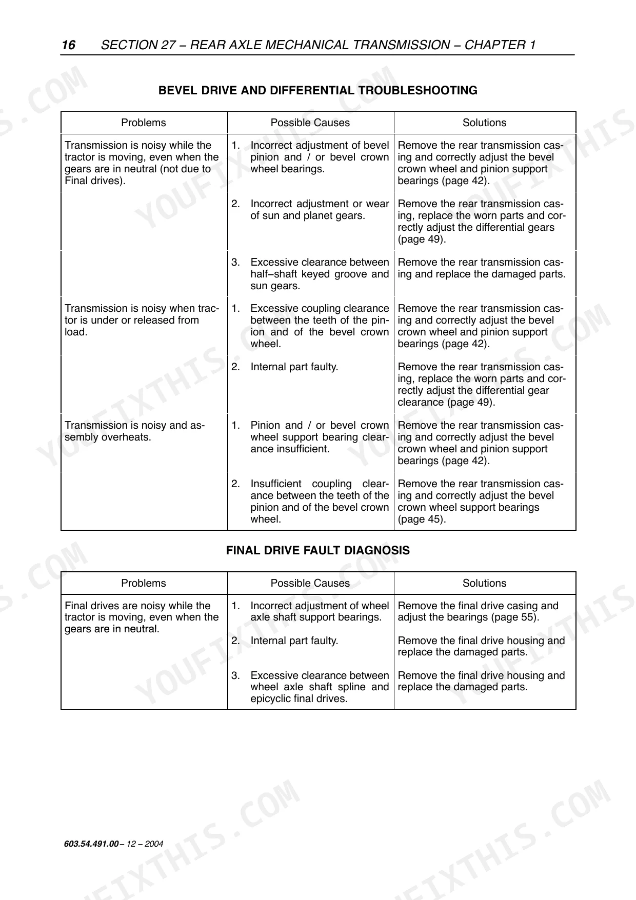
| Rear Mechanical Transmission | Rear Axle and Differential Data, Diff Lock, Final Drives, Description and Operation, Fault Diagnosis, Overhaul | |
| Power Take-Off | PTO Data and Speeds, PTO Clutch and Shafts, Description of Operation, Fault Diagnosis, Housing Removal and Overhaul | |
| Brakes | Service and Parking Brake Data, Hydraulic Brake Circuit and Diagrams, Handbrake Control, Description and Operation, Overhaul | |
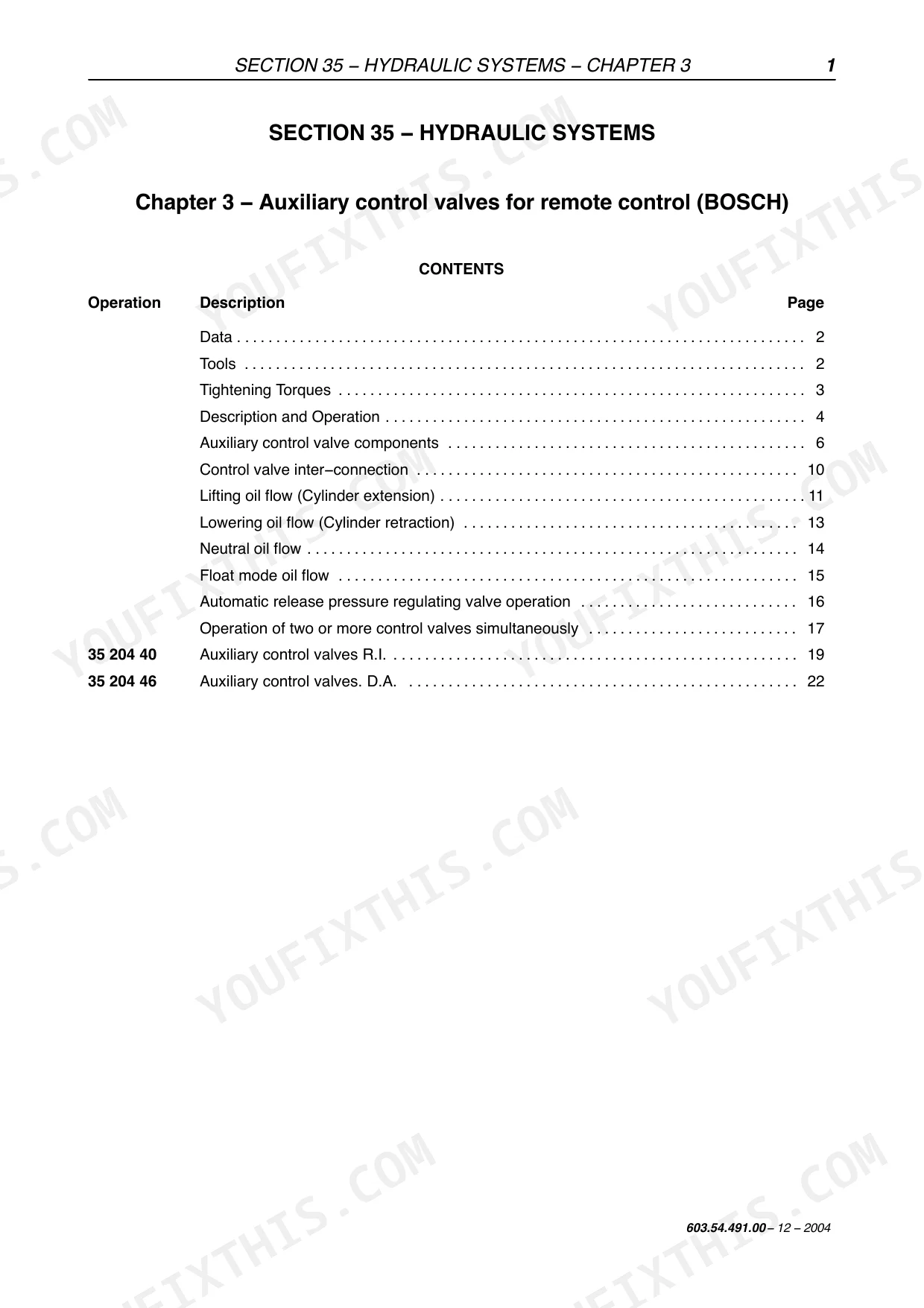
| Hydraulic Systems | Rear Mechanical Hydraulic Lift, Bosch Auxiliary Control Valves, Trailer Brake Auxiliary, Pressure Testing, Lift and Valve Overhaul | |
| Steering | Hydrostatic Steering Control Valve, Steering Pump Components, Data and Tightening Torques, Fault Diagnosis, Overhaul | |
| Axle and Wheels | Front and Rear Axle Data, Front Wheel Track Diagram, Wheel and Tire Fitment, Hub Bearings, Fault Diagnosis and Equipment | |
| Cab Air Conditioning System | Air Conditioning Specifications, Operating Principles, Compressor and Controls, Instruments, Refrigerant Handling, Fault Diagnosis | |
| Electrical System | Instruments and Components, Starting and Charging Systems, Battery, Electrical Circuits and Wiring Diagrams, Sensors and Switches, Diagnostics | |
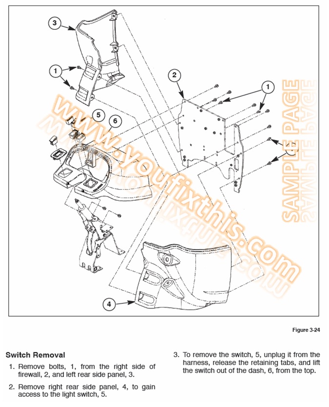
| Platform, Cab and Bodywork | Bonnet, Driver's Seat and Cab Removal and Installation, Doors, Windows, Seals and Padding, Hydraulic Control Lever Guard |
Quick Reference Specifications
| Specification | Value | Page |
|---|---|---|
| TL70A | ||
| Rated Engine Power | 70 hp (53 kW) | |
| TL80A | ||
| Rated Engine Power | 80 hp (60 kW) | |
| TL90A | ||
| Rated Engine Power | 90 hp (67 kW) | |
| TL100A | ||
| Rated Engine Power | 100 hp (73.5 kW) | |
New Holland TL70A, TL80A, TL90A, TL100A Common Problems This Manual Covers
Hydraulic three-point lift is weak or loses pressure.
Usually a failed hydraulic pump seal or contaminated oil. The Hydraulic Systems section covers the rear mechanical lift and BOSCH auxiliary valves with the pressure test points and the pump overhaul to restore lift capacity.
Manual Section: Hydraulic SystemsTransmission slips or will not engage a gear.
Worn clutch components or internal transmission wear are the usual cause. Start with the clutch free-play and checks, then use the Transmission section fault diagnosis, cross-sectional views and overhaul with the reassembly torques.
Manual Section: TransmissionClutch drags or slips.
Set the pedal free-play to the Clutch section spec first, since a mis-adjusted linkage mimics a worn disc. If it still slips, the section covers clutch removal, the checks and measurements and the overhaul with tightening torques.
Manual Section: ClutchEngine runs rough or down on power.
The Engine section covers engine troubleshooting, the compression and injection checks, and the removal, bench assembly and cylinder block and liner measurements to find and fix a down cylinder or worn top end.
Manual Section: EngineFrequently Asked Questions
Does this manual include the wiring diagrams for the TL70A, TL80A, TL90A and TL100A?
Yes. The Electrical System section carries the electrical circuits, starting and charging systems, instruments, sensors and switches, so you can trace an electrical fault instead of guessing at it.
The three-point lift is weak or slow - where does the manual point me?
The Hydraulic Systems section covers the rear mechanical hydraulic lift and the BOSCH auxiliary control valves with the pressure tests and overhaul, so you can find a tired pump seal or contaminated oil and put the lift right.
Does it cover the transmission and clutch overhaul?
Yes. The Clutch and Transmission sections give the data, tightening torques, cross-sectional views, fault diagnosis and the full removal and overhaul procedures for a slipping clutch or worn transmission.
What engine power does each model make?
Rated power is 70 hp (53 kW) on the TL70A, 80 hp (60 kW) on the TL80A, 90 hp (67 kW) on the TL90A and 100 hp (73.5 kW) on the TL100A. The full engine data and tightening torques are in the Engine section.
Does it cover the front-wheel-drive axle and steering?
Yes. The Front Mechanical Transmission and Axle and Wheels sections cover the 4WD front axle, and the Steering section covers the hydrostatic steering control valve and pump with the data, torques and overhaul.
Is this New Holland TL70A, TL80A, TL90A, TL100A manual a digital download?
Immediate download of the complete 1621-page searchable Service Manual (101 MB). Access it on any device, from a laptop at your desk to a phone in the field.
Can I print this New Holland TL70A, TL80A, TL90A, TL100A manual?
No restrictions at all. Print individual pages, full chapters, or the entire manual. The PDF is completely unlocked.


Reviews
There are no reviews yet.