


Part of the New Holland Repair Manuals.
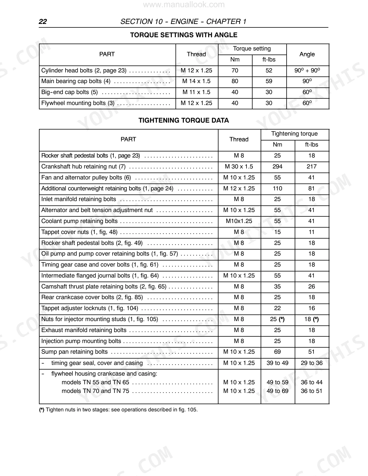
Putting your New Holland TN75, TN70, TN65, or TN55 back to factory spec requires exact data. This 870-page service manual delivers hydraulic schematics with full fluid routing, wiring diagrams for every circuit, and fault code diagnostics. The transmission section alone provides component-level service procedures spanning the front axle, rear mechanical, PTO, brakes, and steering. You will find precise specifications, such as torquing the cylinder head bolts to 70 Nm (52 ft-lbs) followed by two 90° rotations, and main bearing caps to 80 Nm (59 ft-lbs) plus a final 90° turn. Stop relying on forum guesses for angle-torque sequences. The file is fully bookmarked by section and keyword-searchable, allowing you to pull it up on a tablet right next to the tractor.
What's Inside This New Holland TN55, TN65, TN70, TN75 Manual
| System | Pages | Key Topics |
|---|---|---|
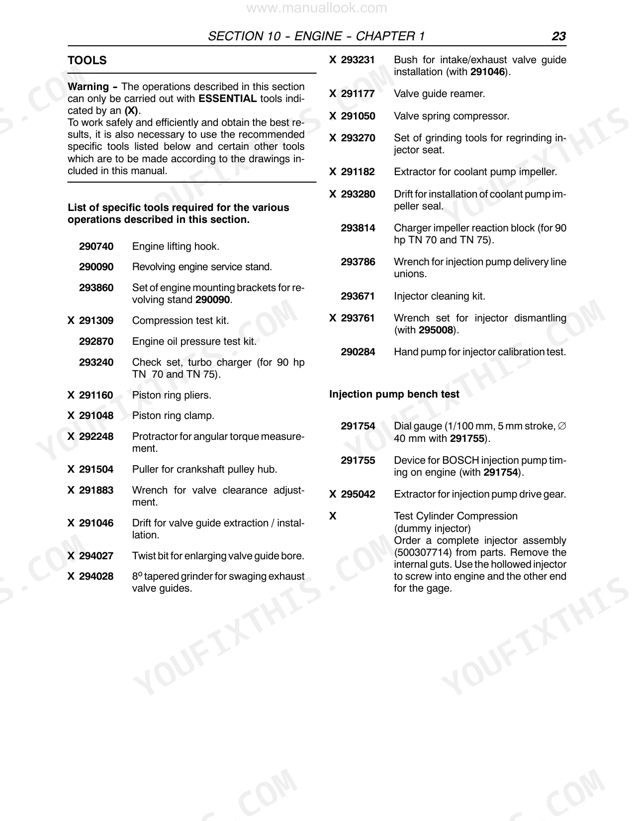
| Engine | 7-106 | Cylinder Head, Timing Gears, Oil Pump, Crankshaft, Connecting Rod, Piston, Tappet, Rocker Arm |
| Clutch | 107-126 | PTO Clutch, Main Clutch, Belleville Spring Disk, Pressure Plate, Flywheel, Clutch Cover, Power Shuttle Gear Control Disk |
| Transmissions | 127-438 | Mechanical Transmission, Synchro-Command, Non-Synchronized Transmissions, Shuttle Unit, Gearbox, Range Gear, Shuttle |
| Drive Lines | 439-452 | Transmission Shafts, Drive Gear Housing Assembly, Drive Gear |
| Front Axle Mechanical Transmission | 453-496 | Front Axle, Bevel Drive, Differential, Epicyclic Final Drive, Steering Knuckle, Wheel Hubs, Axle Pivot |
| Rear Mechanical Transmission | 497-526 | Bevel Gear Pair, Differential, Lateral Final Drives, Rear Transmission Gearbox, Differential Lock Engagement Sleeve |
| Mechanical Power Take-Off | 527-538 | PTO 540 RPM, PTO Cover, Drive Shaft Bearings, PTO Shaft Bearings, Seal Ring, Grooved Terminal, Rear Transmission Housing, Driven Gear Support Bushing |
| Braking System | 539-556 | Service Brake, Parking Brake, Brake Hydraulic Pump, Handbrake Control |
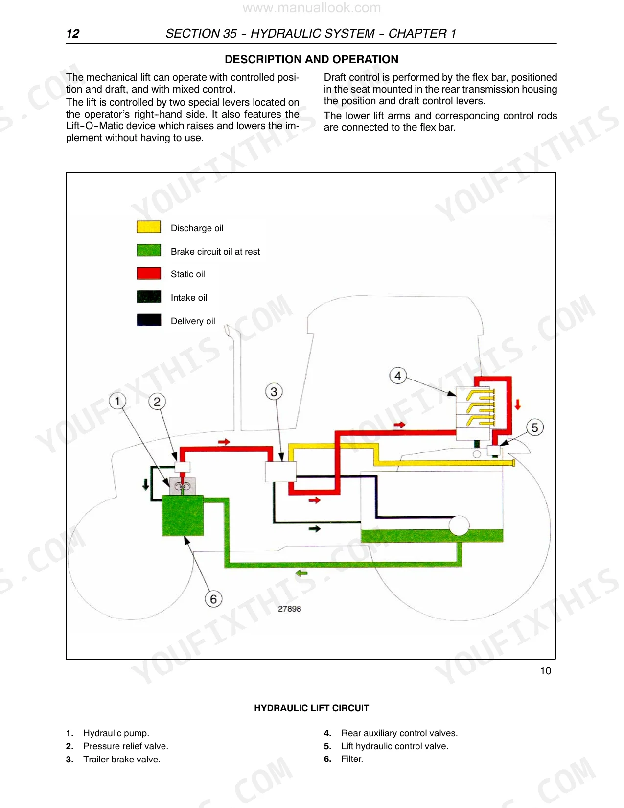
| Hydraulic System | 557-624 | Rear Mechanical Hydraulic Lift, Implement Hitching Device, Lift Internal Controls, Hydraulic Lift Tools, Hydraulic Lift Circuit, Hydraulic Lift Control Valve Block, Draft Control Device |
| Steering | 625-662 | Hydrostatic Steering, Control Valve, Steering Wheel, Rotor, Cylinder Safety Valve, Backflow Valve, Pressure Relief Valve |
| Axles and Wheels | 663-680 | Front Axle Hub, Front Axle, Stub Axle, Leading Wheels |
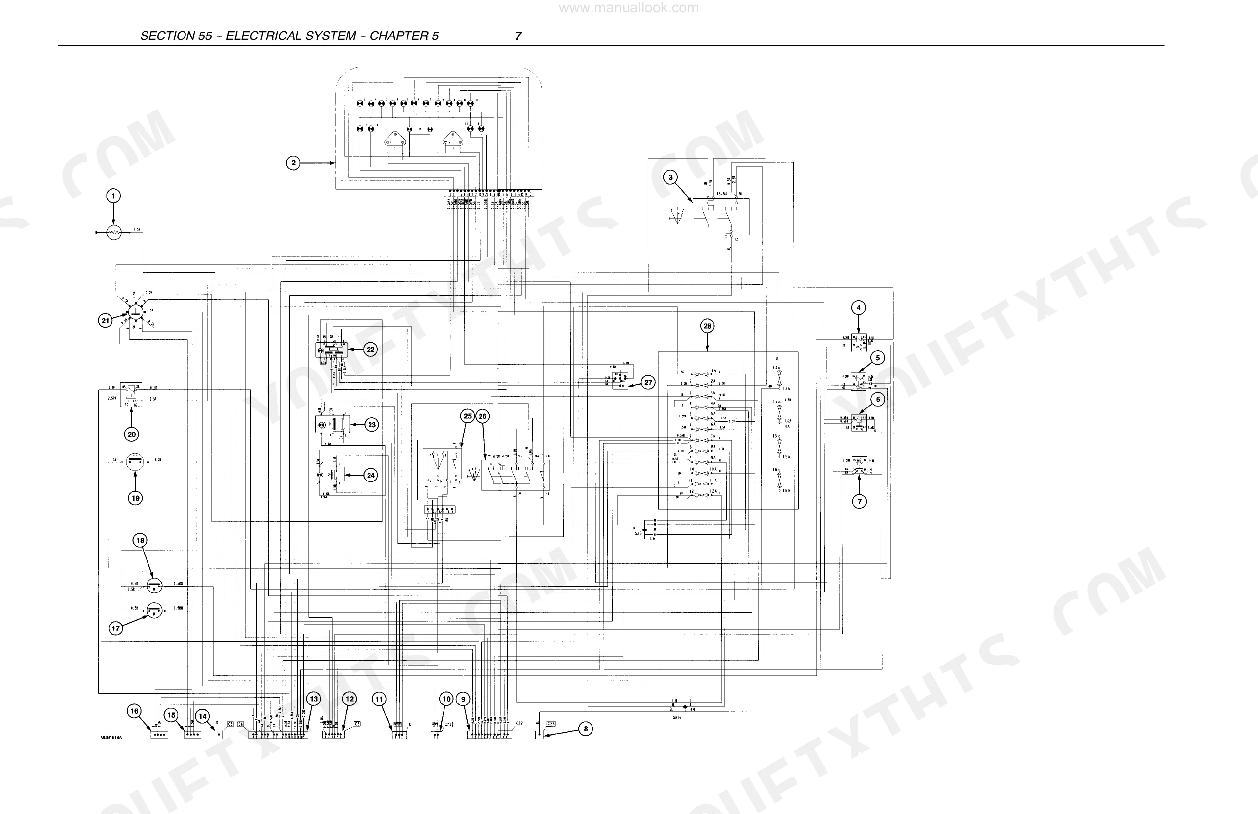
| Electrical System | 681-854 | Analog Instruments, Controls, Transmitters, Sensors and Switches, Starter Motor, Alternator |
| Platform, Cab, Bodywork | 855-870 | Hood Opening, Protective Grill, Hood Guard, Dashboard, ROPS (Roll Over Protection Structure), Right or Left-Hand Mudguard, Rear Guard |
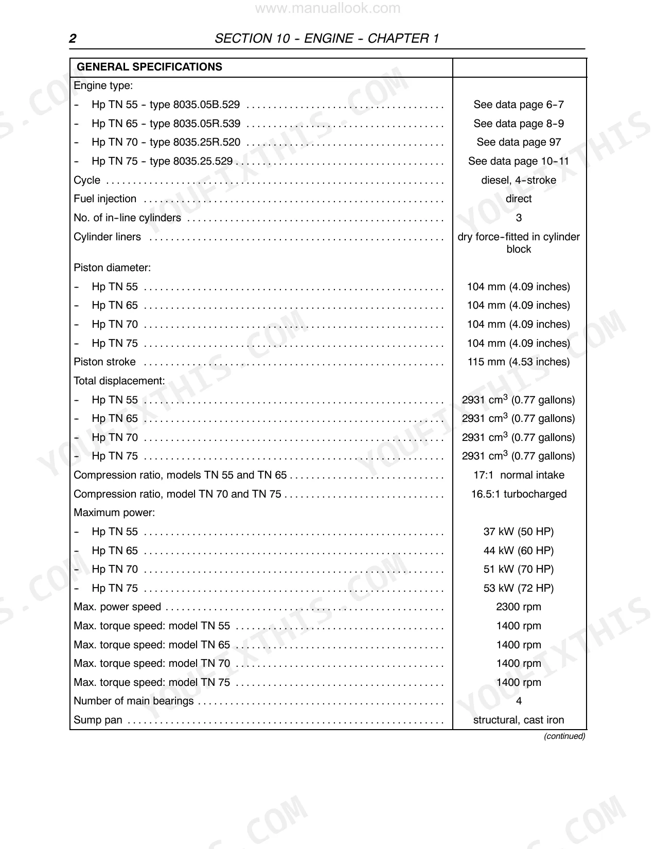
Quick Reference Specifications
| Specification | Value | Page |
|---|---|---|
| Cylinder head bolts torque | 70 Nm (52 ft-lbs) + 90° + 90° | p. 28 |
| Main bearing cap bolts torque | 80 Nm (59 ft-lbs) + 90° | p. 28 |
| Fuel filtering type | replaceable cartridge | p. 10 |
| Air cleaning type | dual cartridge dry air filter | p. 10 |
| Engine oil filter replacement interval | every 400 operating hours | p. 71 |
| Engine oil filter tightening | by hand only, through a further 3/4 turn | p. 71 |
| Power Shuttle hydraulic filter type | paper cartridge | p. 163 |
| Hydraulic lift circuit filter type | full-flow filter, with paper cartridge | p. 598 |
| Thermostat normal working temperature range | 65°C to 105°C (149°F to 221°F) | p. 9 |
| Fan belt deflection (without air conditioning) | 10 to 11 mm (0.3937 to 0.4331 in.) for 78 to 98 N load | p. 705 |
| Fan belt deflection (with air conditioning) | 12 to 13 mm (0.4724 to 0.5118 in.) for 78 to 98 N load | p. 705 |
| Coolant pump retaining bolts torque | 55 Nm (41 ft-lbs) | p. 28 |
New Holland TN55, TN65, TN70, TN75 Common Problems This Manual Covers
Tractor is hard to start, cranks slowly, or won't fire in cold weather
Examine the fuel filter first; replace the replaceable cartridge if it is past its service interval. Inspect all fuel line fittings for air ingress, working from the tank forward. Verify battery voltage and connections before condemning the starter. Injector opening pressure should be 260 to 272 bar (page 11). If cranking is strong but ignition fails, suspect the injectors or pump.
Manual Section: Section 10 - Engine p. 11Coolant temperature climbs into the red during sustained field work
Verify the coolant level, as this engine holds 10.0 liters in the system (page 6). Clean the radiator core and screen of chaff and debris. Inspect fan belt tension, since a loose belt reduces airflow at low engine speeds. Test the thermostat for proper opening. If coolant circulates but temperature keeps rising, suspect a failing water pump impeller.
Manual Section: Section 10 - Engine p. 6Hydraulic lift rises slowly, jerks, or drops implement weight
Assess the hydraulic oil level and condition, because contaminated fluid accelerates wear. Replace the full-flow paper cartridge filter in the lift circuit (page 598). Clear the suction strainer of any debris. The C 42 pump should deliver 19.06 dm3/min at 1000 rpm (page 621). If measured output falls short, rebuild or replace the pump before adjusting lift sensitivity.
Manual Section: Section 35 - Hydraulic System p. 598Clutch slips under load or pedal drags and won't fully release
Inspect the clutch driven plate for wear and glazing before condemning the pressure plate. Check pedal free travel and linkage adjustment first; a slipping clutch often traces back to incorrect pedal height rather than worn friction material. When reinstalling, torque the clutch/flywheel retaining bolts to 20 to 25 Nm (15 to 18 ft-lbs) per page 108.
Manual Section: Section 18 - Clutch p. 108Frequently Asked Questions
How do I reset the hydraulic or transmission warning light on a New Holland TN55?
To reset the hydraulic or transmission warning light, the underlying fault must first be resolved. The error code is then cleared using the CDU (Calibration/Diagnostic Unit) via the HF Menu, as indicated in the "Recovery" sections for specific fault codes (e.g., page 234). p. 432
What do the New Holland TN65/TN70/TN75 error codes mean?
The manual provides a comprehensive list of fault codes for the Power Shuttle system, including their priority, correction, and effect, starting on page 193 in SECTION 21 - TRANSMISSIONS, Chapter 2. For example, Fault Code 11 (CPDL_POT_LO_DISABLING_ERR) has a priority of 14 and results in the transmission being disabled. p. 193
What are the torque specs for New Holland TN series wheel bolts or head bolts?
The torque specifications for New Holland TN series include: Cylinder head bolts (M 12 x 1.25) should be tightened to 70 Nm (52 ft-lbs) plus 90° + 90° (page 28). Rim to hub retaining bolts (M 18X1.5) require a torque of 170 to 206 Nm (125-151 ft-lbs) (page 456). p. 28
How do I bleed the fuel system on a New Holland TN55 after replacing the filter?
To bleed the fuel system after replacing the filter, unscrew the bleeder plug (1) by approximately 2 turns, then operate the priming lever (1, fig. 150) until fuel flows free of air bubbles. Finally, tighten the plug (1) and loosen the fuel supply lines unions on the three injectors, operating the priming lever again until fuel is free of air bubbles before tightening the unions (page 97). p. 97
How will I receive this Service Manual?
Immediate download of the complete 870-page searchable Service Manual. Access it on any device, from a laptop at your desk to a phone in the field.
Can I print this manual?
Absolutely. No DRM or copy protection. Print the whole manual or just the pages you need. Any home or office printer works.
Does this New Holland TN55, TN65, TN70, TN75 manual cover the hydraulic?
Yes, this New Holland TN55, TN65, TN70, TN75 Service Manual includes hydraulic system diagrams, circuit schematics, and component specifications.