


Part of the Yanmar Parts Manuals.
Need the right factory parts for your 1989-1995 Yanmar B6 crawler backhoe? This 181-page OEM parts catalog (part no. Y00K2591) covers every component with numbered exploded diagrams, complete parts lists, and factory cross-references. You get the full wiring diagram to trace any electrical circuit, hydraulic schematics for the control valves and cylinders, specifications for B6-P and B6-PR variants, and a detailed picturesque index so you can pinpoint any part by location before looking up its number. Load the bookmarked PDF on a tablet, find the exact part number, and order with confidence.
What's Inside This Yanmar B6 Parts Manual
| System | Pages | Key Topics |
|---|---|---|
| Preface | 1 | Yanmar B6 Parts Catalog History, Model Name Index, Machine Serial Numbers, Japan & Overseas Edition |
| Specifications | 2 | Model Variants B6/B6-P/B6-PR, Engine 4TN84L-Rbb, Dimensions, Bucket Capacity, Max Digging Depth, Travel Speed 4.3-2.2 km/h (B6-P) / 4.5-2.3 km/h (B6-Pr), Machine Mass |
| Paint & Color Reference | 3-7 | Table of Painted Colors (4 Variants), Paint Part Numbers, Saffron Yellow, Charcoal Gray, Cream White, Red1, Deep Green, Mint Green, New Permanent Yellow, Dark Olive Gray |
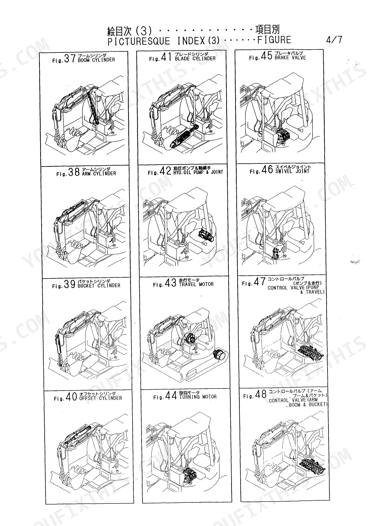
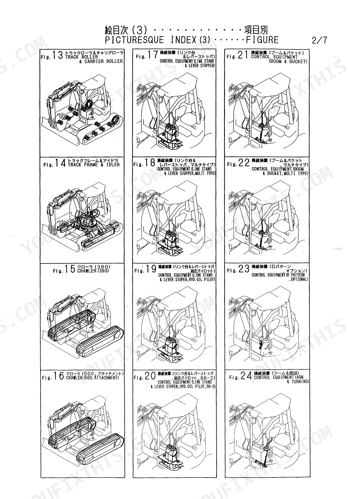
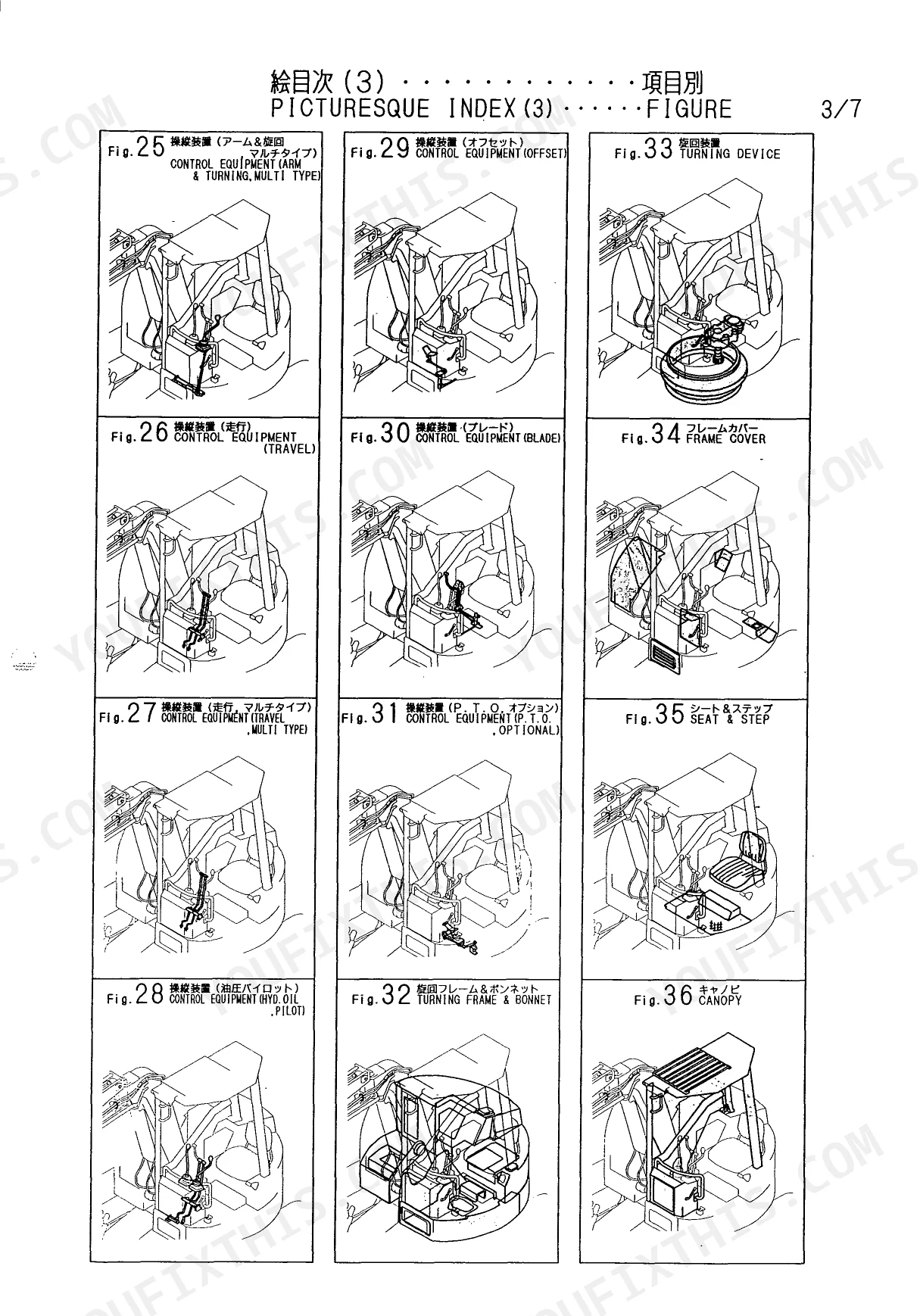
| Picturesque Index, Main & Hydraulic Sections | 8-9 | Main Parts Overview (Engine Mount, Radiator, Fuel Tank, Battery, Electric Part, Track Roller, Turning Frame, Boom, Arm, Cylinders), Hydraulic Section Index (Travel Motor, Swivel Joint, Control Valve, Oil Pump, Pilot Valve) |
| Picturesque Index, Attachment & Figures | 10-16 | Chassis Parts, boom/arm/bucket Assembly, Cab & Canopy, Track & Control Equipment, Bucket Attachments (550/600/650/700/750/330/S-Type), Blade |
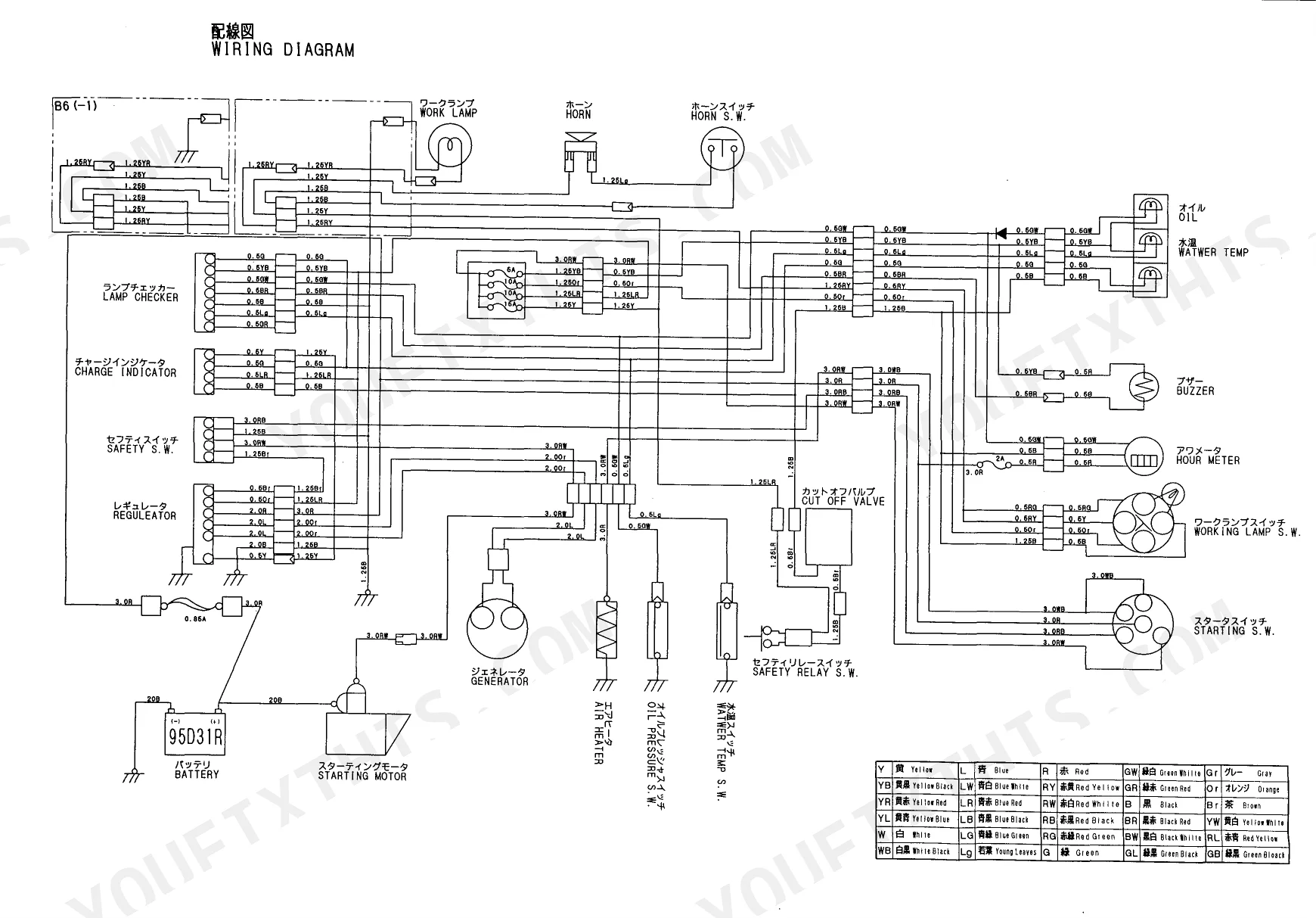
| Wiring Diagram | 17-19 | Label Set, Specification Label, Oil/water Label, Greasing Label, Offset Stopper Label, B6 Label, Stripe a Label, Restart Label |
| Labels & Tools | 20-29 | Label Set, Specification Label, Stripe a Label, Offset Stopper Label, Stripe C Label, Oil & Water Label, Offset E Label, Start Switch Label |
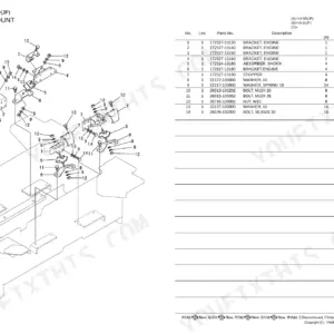
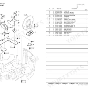
| Crawler (500, Attachment) | 30-52 | Support, Bracket, Eng Bracket, Engine Stopper, Shock Absorber, Mount, Water Drain Hose, Hose .5X13 |
| Control Equipment (Arm & Turning) | 53-68 | Link, Bush, Pedal, Shaft, Pedal Lock, Pedal Pad, Spool Link, Elball |
| Turning Frame & Bonnet | 69-84 | Lever Assy, Bush, Lever Knob, Link Assy, Shaft Assy, Grease Nipple B, Grease Nipple C, Rod |
| Remote Control Valve & Cut Off Valve | 85-127 | Cover, Mount Cover, Guard Plate, Driving Cover, Rail, Plate Assy, Rubber Cover, Rubber |
| Hyd. Oil Piping (Return) | 128-143 | Valve, Tie-Rod, Inlet Section Assy, Outlet Section, Spool Section Assy, Relief Valve Assy, Hydraulic Oil Tank Assy, Filter Support Rod |
| Boom | 144-159 | Tube, Offset Tube, Bucket Tube, Arm Tube, Hose Guide, Hose, Guide, Connector |
| Bucket330 (Attachment) | 160-176 | Arm, Bush 50X80, Spacer .5X33, Dust Seal 50X60X4, Seal Dkiy 45X55X4, Dust Seal VAY45X55X4, Bucket Arm, Bucket Link |
| Safety Label (B6-2) | 177-181 | Lock Plate, Blade Assy, Bush 45X40, Dust Seal 45X55X4, Grease Nipple PT1, Grease Nipple B, Spacer, Label a |
Quick Reference Specifications
| Specification | Value | Page |
|---|---|---|
| All Models | ||
| Fuse Current Rating | 5A | p. 39 |
| B6-P | ||
| Travel speed (high-low) | 4.3 - 2.2 km/h | p. 2 |
| B6-PR | ||
| Travel speed (high-low) | 4.5 - 2.3 km/h | p. 2 |
Yanmar B6 Common Problems This Manual Covers
Yanmar B6 undercarriage part numbers needed for worn components and severely slow travel speed
Review the technical specifications on page 2. Verify your model to order the right undercarriage parts. B6-P models are rated for 4.3 - 2.2 km/h travel speed. Find the exact track roller and sprocket part numbers corresponding to your specific serial number range.
Manual Section: Specifications p. 2Control panel wiring harness diagram needed to fix severe intermittent electrical power loss
Inspect the wiring diagram legend on page 17 to trace the damaged circuit. Locate the 10A fuse part number in the electrical system exploded view. Order the exact factory replacement fuse and matching wiring connectors from the parts list.
Manual Section: Wiring Diagram Legend p. 17Lighting circuit fuse part numbers required for completely dead work lights and unresponsive gauges
Check the wiring diagram legend on page 17 to trace the lighting circuit paths. Search the electrical catalog section for the required 15A fuse part number. Verify the color codes for the yellow and blue wires before ordering replacement harness sections.
Manual Section: Electrical System Issues p. 17Ignition switch and starter relay part numbers needed for unresponsive starter relay clicking
Examine the wiring diagram legend on page 17 to locate the starter relay harness. Find the 5A fuse part number required for the starting circuit. Cross-reference the engine parts diagram to secure the correct replacement ignition switch and associated electrical connectors.
Manual Section: Electrical System Issues p. 17Frequently Asked Questions
How do you fix undercarriage part numbers needed for worn components and severely slow travel speed?
Review the technical specifications on page 2. Verify your model to order the right undercarriage parts. B6-P models are rated for 4.3 - 2.2 km/h travel speed. Find the exact track roller and sprocket part numbers corresponding to your specific serial number range. p. 2
How do you fix control panel wiring harness diagram needed to fix severe intermittent electrical power loss?
Inspect the wiring diagram legend on page 17 to trace the damaged circuit. Locate the 10A fuse part number in the electrical system exploded view. Order the exact factory replacement fuse and matching wiring connectors from the parts list. p. 17
How do you fix lighting circuit fuse part numbers required for completely dead work lights and
Check the wiring diagram legend on page 17 to trace the lighting circuit paths. Search the electrical catalog section for the required 15A fuse part number. Verify the color codes for the yellow and blue wires before ordering replacement harness sections. p. 17
What format is this Yanmar B6, BUCKET 550, BUCKET 600, BUCKET 650, BUCKET 700?
You get a 181-page searchable PDF (5 MB) that downloads instantly after checkout. Open it on your laptop, tablet, or phone, and bring it right to the shop floor.
Is this Yanmar B6, BUCKET 550, BUCKET 600, BUCKET 650, BUCKET 700, BUCKET 750?
Absolutely. No DRM or copy protection. Print the whole manual or just the pages you need. Any home or office printer works.
Does this Yanmar B6, BUCKET 550, BUCKET 600, BUCKET 650, BUCKET 700, BUCKET?
Yes, this Yanmar B6, BUCKET 550, BUCKET 600, BUCKET 650, BUCKET 700, BUCKET 750, BUCKET330, BUCKET S TYPE, 450S, 750S, 700S, 650S, 600S, BLADE Parts Catalog includes a wiring diagram for the electrical system.
Reviews
There are no reviews yet.