


Part of the Yanmar Parts Manuals.
Tracking down replacement components for your 2004 crawler backhoe is simple with this 173-page Yanmar B7-5A parts catalog PDF (OEM #Y00S4320). Inside, you get highly detailed exploded views covering the entire boom cylinder assembly, undercarriage crawlers, and the complete engine block. Open to exact hydraulic piping breakdowns for the travel motors and full electrical schematics that map out every wiring harness and connector routing. Verify your main electrical protection with the 50A slow blow fuse rating, or confirm the exact spec for a 12V55W headlight bulb before calling the dealer for replacements. Stop wasting time ordering the wrong components from confusing aftermarket sites. Download the securely bookmarked file, pull up the right schematic on your tablet, and get your equipment back to work.
What's Inside This Yanmar B7-5A Parts Manual
| System | Pages | Key Topics |
|---|---|---|
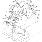
| Fuel System | Air Cleaner, Accelerator Lever, Fuel Tank, Fuel Line | |
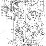
| Cooling System | Radiator & Sub-Tank, Radiator Mount | |
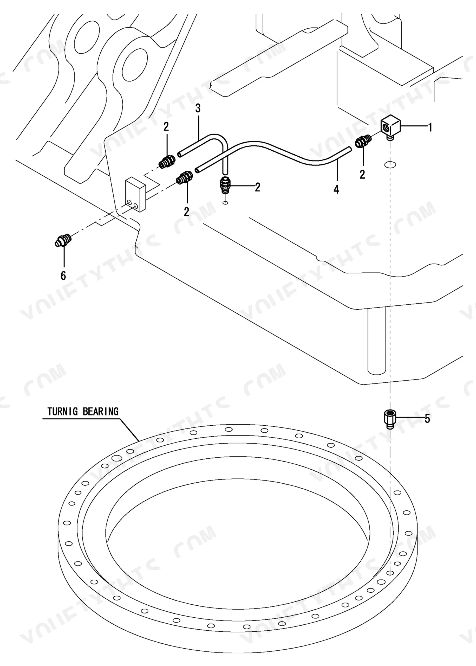
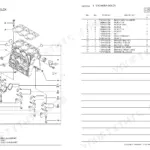
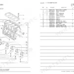
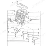
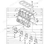
| Engine | Muffler, Frame & Turning Bearing, Hyd. Oil Pump & Joint, Lub. Oil Cooler | |
| Electrical System | Battery | |
| Hydraulics & 3-Point Hitch | Control Valve Plate, Boom Cylinder, Arm Cylinder, Bucket Cylinder, Blade Cylinder, Offset Cylinder, Control Valve, Remote Control Valve | |
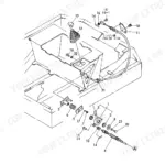
| Body & Operator Station | Cover, Step & Instrument Panel, Seat Mount, Bonnet, Cabin Mount, Hyd. Oil Tank | |
| Decals & Accessories | Label, Safety Label | |
| Other Components | Engine Mount, Electric Part, Indicator Box, Wind Washer, Heater, Defroster, Sprocket & Roller, Idler & Crawler Adjust, Crawler, Control Equipment, Travel Motor, Turning Motor, Accumulator, Swivel Joint, Hyd. Oil Piping, Control Piping |
Quick Reference Specifications
| Specification | Value | Page |
|---|---|---|
| Fuse Rating | 30A | p. 37 |
| Fuse Rating (Slow Blow) | 50A | p. 37 |
| Headlight Bulb Voltage/Wattage | 12V55W | p. 39 |
| Indicator Box Bulb Voltage/Wattage (Type T6.5) | 13.5V-2W | p. 41 |
| Indicator Box Bulb Voltage/Wattage (Type T5) | 14V-2W | p. 41 |
| Spring Dimension (Travel Motor) | 22.5/7X92/8.2 | p. 92 |
| Shim Thickness (Travel Motor) | 32X45X0.3 | p. 92 |
| O-Ring Dimension (Swivel Joint) | 1A P-80.0 | p. 111 |
| O-Ring Dimension (Hyd. Oil Tank) | 1A G-135.0 | p. 131 |
| O-Ring Dimension (Control Valve) | 1A G70.0,NBR | p. 113 |
Yanmar B7-5A Common Problems This Manual Covers
Need the correct hydraulic tank seal replacement part numbers for Yanmar B7-5A(EP) due to fluid weeping at the reservoir base
Inspect the Hyd. Oil Tank exploded view on page 58 to find the reservoir assembly components. Verify the exact O-Ring Dimension is 1A G-135.0 from page 131 before ordering. Cross-reference the strainer and suction filter part numbers while you have the tank open.
Manual Section: Hyd. Oil Tank p. 58Main power completely dead and need to locate the exact slow blow fuse part number for intermittent power loss
Check the Bonnet (Side & Rear Cover) breakdown on page 37 to identify the fuse block components. Order the exact 50A Fuse Rating (Slow Blow) replacement part listed in the index. Inspect the surrounding harness and connectors for visible burning or damage.
Manual Section: Bonnet (Side & Rear Cover) p. 37Trying to find the correct spring and shim part numbers after the travel motor starts making grinding noises
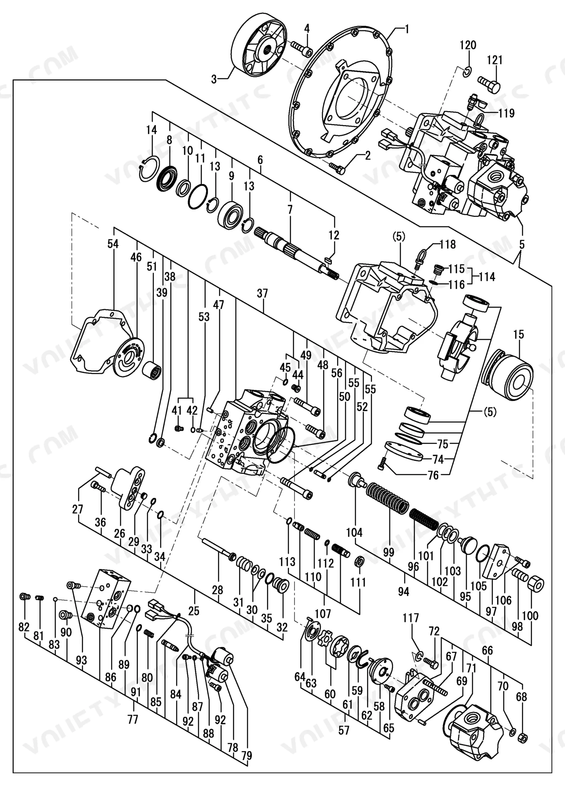
Review the Travel Motor assembly diagrams on page 45 for the exact piston seal and swash plate part numbers. Order the required 22.5/7X92/8.2 Spring Dimension and 32X45X0.3 Shim Thickness parts shown on page 92 to complete the final rebuild properly.
Manual Section: Travel Motor p. 45Need the right swivel joint seal kit part numbers to fix severe hydraulic fluid leaks and pressure loss
Open the Swivel Joint parts breakdown on page 48 to locate the main shaft and seal assembly numbers. Ensure you order the correct 1A P-80.0 O-Ring Dimension specified on page 111 to rebuild the hub. Replace the thrust washer at the same time.
Manual Section: Swivel Joint p. 48Frequently Asked Questions
What are the replacement specifications for hydraulic hoses?
The manual provides replacement specifications for hydraulic hoses in the form of part numbers and descriptive names. For example, the "HYD.OIL PIPING" section lists "HOSE H108CX147" with part number 172455-78170 on page 135, and "HOSE H208BC068S" with part number 172455-78210 on page 137. These details are crucial for ordering the correct replacement parts. p. 135
What are the replacement specifications for engine filters (air, oil, fuel)?
The manual provides replacement specifications for engine filters in the form of part numbers and descriptive names. For the air filter, the "ELEMENT" is part number 129062-12560 (page 21). For the fuel filter, the "ELEMENT" is part number 119802-55710 (page 33). The manual also lists hydraulic filters, such as "FILTER" part number 172164-73660 (page 91) and "FILTER ASSY, RETURN" part number 172187-73700 (page 131). p. 21
How do you fix the hydraulic tank seal replacement part numbers for Yanmar B7-5A due to fluid weeping at the reservoir base?
Inspect the Hyd. Oil Tank exploded view on page 58 to find the reservoir assembly components. Verify the exact O-Ring Dimension is 1A G-135.0 from page 131 before ordering. Cross-reference the strainer and suction filter part numbers while you have the tank open. p. 58
How do you fix main power completely dead and need to locate the exact slow blow fuse part number for intermittent power loss?
Check the Bonnet (Side & Rear Cover) breakdown on page 37 to identify the fuse block components. Order the exact 50A Fuse Rating (Slow Blow) replacement part listed in the index. Inspect the surrounding harness and connectors for visible burning or damage. p. 37
How will I receive this Yanmar B7-5A Parts Catalog?
This is a 173-page searchable PDF ready for immediate download. Works on any device, so pull it up on your phone while you are under the hood. No shipping, no waiting.
Is this Yanmar B7-5A Parts Catalog printable?
Yes. The PDF has no DRM restrictions, so print any page or section you need for your shop. Works with any standard printer.
Are there hydraulic diagrams in this Yanmar B7-5A Parts Catalog?
Yes. This parts catalog includes exploded hydraulic piping and component diagrams (HYD.OIL PIPING / Hyd. Oil Tank) on pages 58, 131, 135, and 137, showing individual component part numbers and assembly layouts. Note: this is a parts catalog, not a workshop circuit schematic.
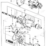

![Yanmar B22-2 C(R)EP, B22-2 P(R)EP, B22-2 P[R], B22-2 C[R] exploded view diagram of the engine mount assembly components.](https://youfixthis.com/wp-content/uploads/2026/06/yanmar-b22-2-to-c-r-crawler-backhoe-parts-catalog-y00s3241-engine-parts-22-150x150.webp)
Reviews
There are no reviews yet.