


Part of the Yanmar Parts Manuals.
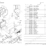
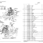
All 45 pages of this Yanmar TB014, TB016, 3TNE68-NTB, 3TNE68-TB1, and ETB1 Parts Catalog (OEM #Y00D6550, Y00D6701) exist for one purpose: finding the exact part number before you order. Inside, you get exploded views and numbered parts lists for every major assembly, from cylinder block and crankshaft to fuel injection pump, governor, starting motor, and generator. The cross-reference index at the back lets you look up any part number and trace it to its assembly group in seconds. Interchangeability marks and effective machine numbers are called out right on the diagrams, so you know immediately whether a part fits your specific variant. Your machine is down and you need the right number, not a guess from a supplier who isn't sure. Bookmarked by section, searchable by keyword: open it on your phone, pull the part number, make the call.
What's Inside This Yanmar TB014 / TB016 Parts Manual
| System | Pages | Key Topics |
|---|---|---|
| How to Read This Parts Catalog | 1 | Ref. No. Explanation, Level Indication, Change Mark, Interchangeability Mark, Effective Machine No., Remarks Mark |
| Contents | 2 | List of Major Groups, Page References |
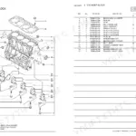
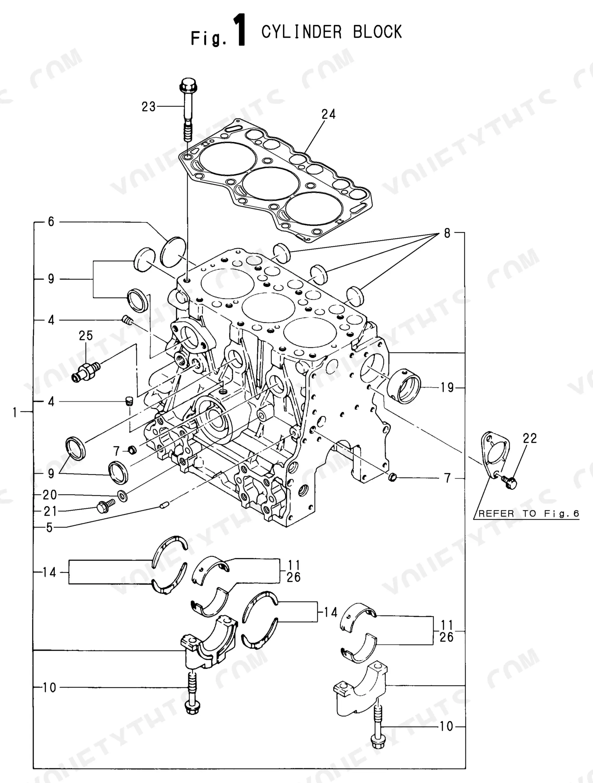
| Cylinder Block | 3 | Block Assembly, Plugs, Bolts, Main Bearings, Thrust Bearings |
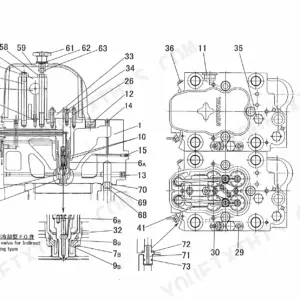
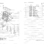
| Gear Housing | 4-5 | Gear Case Assembly, Oil Seal, Pump Assembly, Bolts, O-Rings, Covers, Bearings |
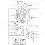
| Flywheel Housing & Oil Sump | 6 | Flywheel Housing, Oil Sump Assembly, Drain Plug, Oil Seal, Bolts, Parallel Pins |
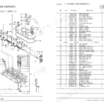
| Cylinder Head & Bonnet | 7-8 | Head Assembly, Valve Guides, Valves, Springs, Rocker Arm Assembly, Glow Plugs, Bonnet Assembly |
| Suction Manifold & Air Cleaner | 9 | Suction Manifold, Air Cleaner Assembly, Element, Indicator, Intake Pipes, Clamps |
| Exhaust Manifold & Silencer | 10 | Exhaust Manifold, Gaskets, Silencer Assembly, Tail Pipe, Bolts, Nuts |
| Camshaft & Driving Gear | 11 | Camshaft Assembly, Tappets, Push Rods, Cam Gear, Idle Gear, Bearings, F.I. Pump Cam |
| Crankshaft & Piston | 12 | Crankshaft Assembly, Pistons, Piston Rings, Connecting Rods, Main Bearings, Thrust Bearings, V-Pulley |
| Lub. Oil System | 13 | Oil Pump Assembly, Oil Filter, Dipstick, Oil Intake Pipe, Oil Pressure Switch |
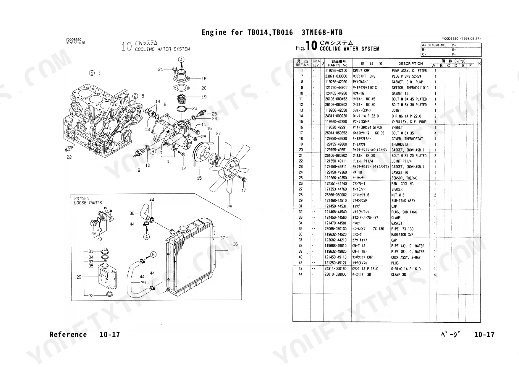
| Cooling Water System | 14 | Water Pump Assembly, Thermostat, V-Pulley, Fan, Radiator, Sub-Tank, Hoses |
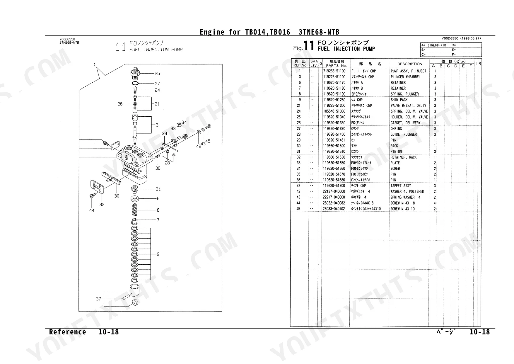
| Fuel Injection Pump | 15 | Pump Assembly, Plungers, Delivery Valves, Rack, Pinion, Tappet Assembly |
| Governor | 16-17 | Case, Weights, Links, Levers, Springs, Regulator Shaft, Stop Device |
| Fuel Injection Valve | 18 | Injection Valve Assembly, Nozzles, Holders, Springs, Fuel Pipes, Clamps |
| Fuel Line | 19-20 | Fuel Filter, Strainer, Feed Pump, Fuel Pipes, Water Separator, Hoses |
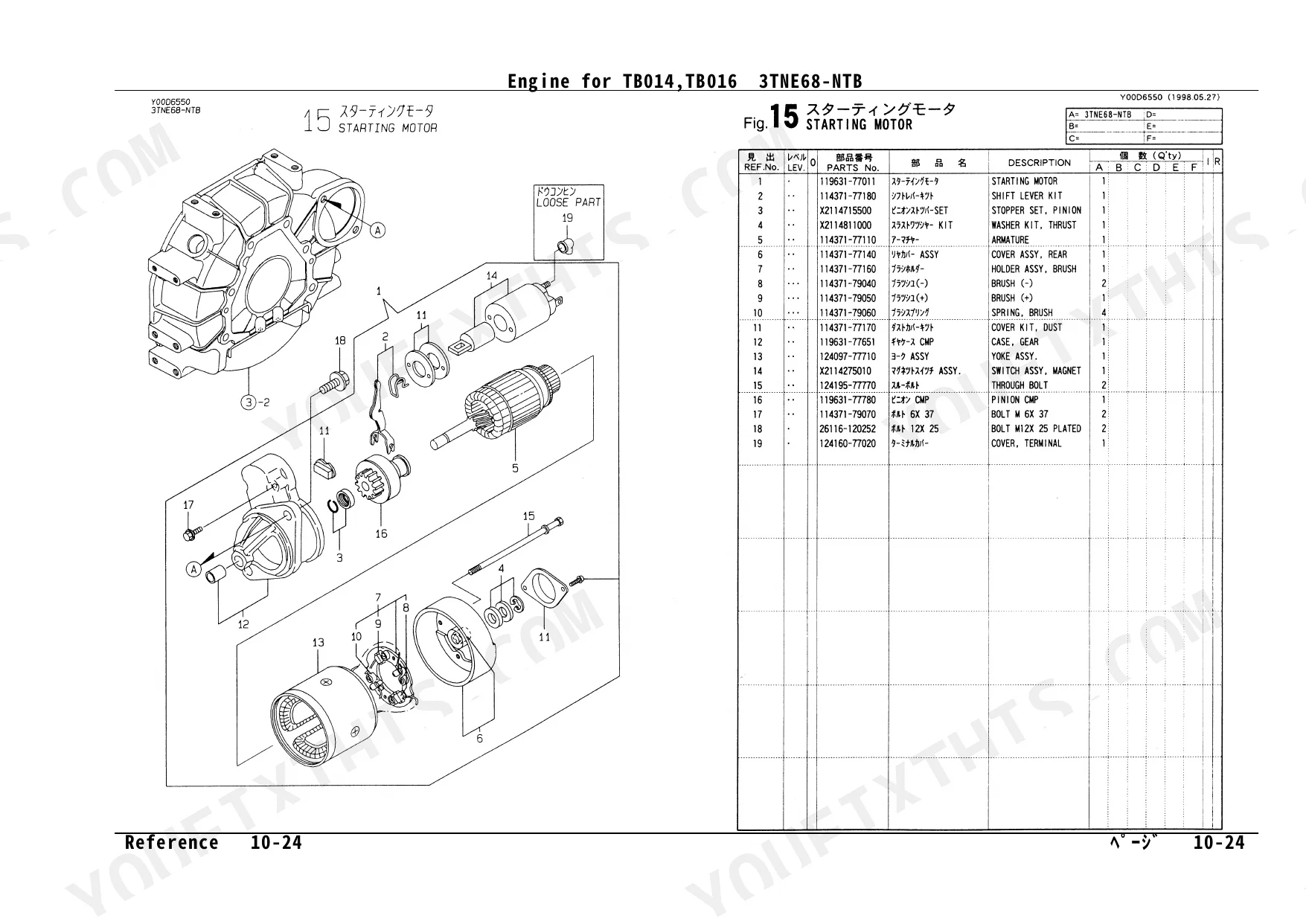
| Starting Motor | 21 | Assembly, Armature, Brush Holder, Pinion, Solenoid Switch |
| Generator | 22 | Assembly, Flywheel, Adjuster, Brushes, Voltage Regulator |
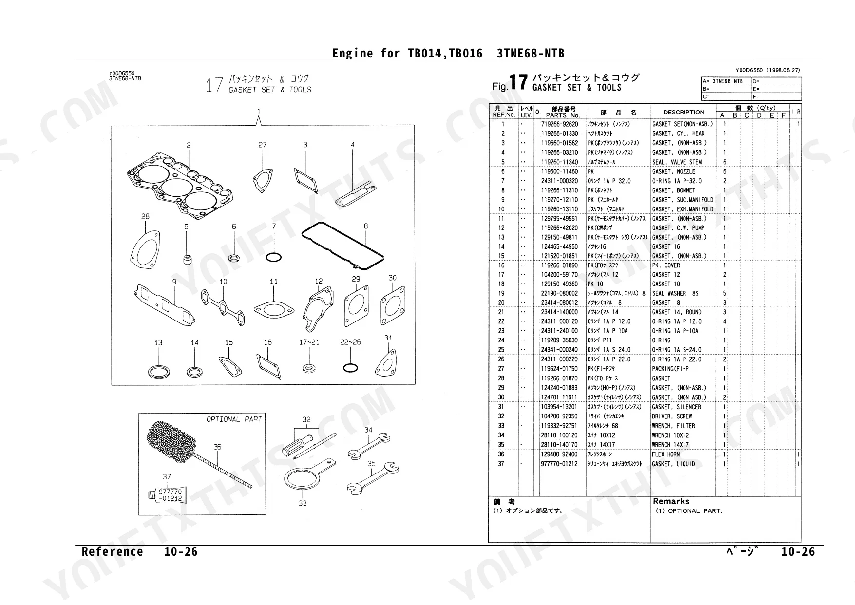
| Gasket Set & Tools | 23 | Complete Gasket Set, Individual Gaskets, O-Rings, Oil Seals, Tools (Screwdriver, Filter Wrench, Spanners) |
| Parts No. Index | 24-25 | Part Number Lookup, Cross-Reference |
Quick Reference Specifications
| Specification | Value | Page |
|---|---|---|
| Main Bearing Under-size | 0.25 | p. 3 |
| Parallel Pin Size | 8x16 mm | p. 6 |
| Drain Plug Size | M22 | p. 6 |
| Vinyl Pipe Size | 12x500 mm | p. 7 |
| Plug Size | PT 1/16 | p. 7 |
| Thermo Switch Setting | 110°C | p. 14 |
Yanmar TB014 / TB016 Common Problems This Manual Covers
Yanmar TB014/TB016 fuel filter O-ring part number needed to fix air ingress and hard starting
Turn to the Fuel Line exploded view on page 19. Locate the fuel filter assembly in the parts list and cross-reference the O-ring ref numbers against the Parts No. Index on page 24 to confirm exact part numbers for your serial range. Check the interchangeability marks on page 1 before ordering, some O-rings share part numbers across the TB014 and TB016.
Manual Section: Fuel Line p. 19Can't identify correct injection nozzle and holder assembly part numbers for white smoke diagnosis
Open the Fuel Injection Valve exploded view on page 18. The nozzle and holder are listed as a sub-assembly, note both ref numbers separately, since nozzles and holders are often ordered independently. Cross-check both part numbers in the Parts No. Index on page 24 and verify the effective machine number column applies to your serial range.
Manual Section: Fuel Injection Valve p. 18Need fuel injection pump plunger and delivery valve part numbers after contaminated fuel damage
Go to page 15 for the Fuel Injection Pump exploded view. Plungers, delivery valves, and the rack and pinion assembly are each listed with individual ref numbers. Write down all ref numbers before calling the dealer, the pump tappet assembly is a separate line item. Confirm interchangeability marks per the guide on page 1, as plunger kits sometimes changed effective machine numbers mid-production.
Manual Section: Fuel Injection Pump p. 15Correct part numbers for valve guides, valves, and springs after worn valve seat causes compression loss
Check the Cylinder Head and Bonnet diagram starting on page 7. Intake and exhaust valves, guides, and springs each carry distinct ref numbers, do not assume they are interchangeable between positions. The complete gasket set on page 23 includes the head gasket and valve cover gasket; order it alongside individual valve components to avoid a second disassembly.
Manual Section: Cylinder Head & Bonnet p. 7Oil filter and oil pump assembly part numbers needed after low oil pressure warning and bearing damage concern
Locate the Lub. Oil System diagram on page 13. The oil filter, oil intake pipe, and oil pressure switch are listed as separate line items, order all three if the engine showed low pressure. The Parts No. Index on page 24 lets you verify each part number independently. If main bearings need replacement, the undersized bearing (U.S. = 0.25) is listed on page 3 under Cylinder Block.
Manual Section: Lub. Oil System p. 13Water pump and thermostat part numbers needed after overheating event on a Yanmar compact engine
Reference the Cooling Water System diagram on page 14. The water pump assembly, thermostat, and thermo switch (rated 110°C) are each separate line items. Cross-reference part numbers in the Parts No. Index on page 24 before ordering. If hoses or the radiator sub-tank also need replacement, all cooling hoses are listed on the same page 14 diagram.
Manual Section: Cooling Water System p. 14Frequently Asked Questions
What are the replacement specifications for fuel filter?
For the fuel filter, the manual specifies the fuel strainer (Part No. 119255-55620) and the fuel element (Part No. 124550-55700, L=90). These part numbers identify the correct components for replacement in the fuel line system.
What format is this Yanmar TB014, TB016, 3TNE68-NTB, 3TNE68-TB1, ETB1 manual in?
Immediate download of the complete 45-page searchable Parts Catalog (22 MB). Access it on any device, from a laptop at your desk to a phone in the field.
Can I print specific sections of this Yanmar TB014, TB016, 3TNE68-NTB?
No restrictions at all. Print individual pages, full chapters, or the entire manual. The PDF is completely unlocked.
Reviews
There are no reviews yet.