


Part of the Yanmar Parts Manuals.
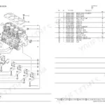
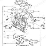
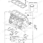
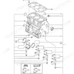
All 131 pages of this Yanmar Vio40-2 Parts Catalog exist for one purpose: getting you the right part number for your 2001 Crawler Excavator the first time. Inside, you get a fully indexed picturesque parts index covering every major assembly, from the hydraulic oil pump and swivel joint to the travel motor, boom cylinders, and remote control valves. Engine, hydraulic, cab, chassis, drivetrain, boom, and controls are all broken out into dedicated sections with exploded views and cross-referenced part numbers. Need the accelerator O-ring? It's a 27x5.7 dimension, cataloged and ready. Ordering the wrong part and waiting three weeks for a replacement costs more than this catalog. Download it now, search by assembly name, and pull the exact Yanmar part number before you call the dealer. Bookmarked by section; find any assembly in seconds on your laptop or tablet.
What's Inside This Yanmar Vio40-2 Parts Manual
| System | Pages | Key Topics |
|---|---|---|
| Preface | 1-1 | Model Name, I (Vehicle), Ii (Engine) |
| Painted Color List | 2-2 | Yanmar Deep Green, Yanmar New Permanent Yellow, Yanmar New Grayish Green, Yanmar Dark Olive Gray, Yanmar Black, Yanmar Warm Gray |
| Paint Part No | 3-3 | Paint Part Numbers, Color SKUs, Coating Specifications by Component |
| Color of Main Parts | 4-4 | Per-Component Color Assignment: Upper Structure, Boom, Arm, Bucket, Undercarriage |
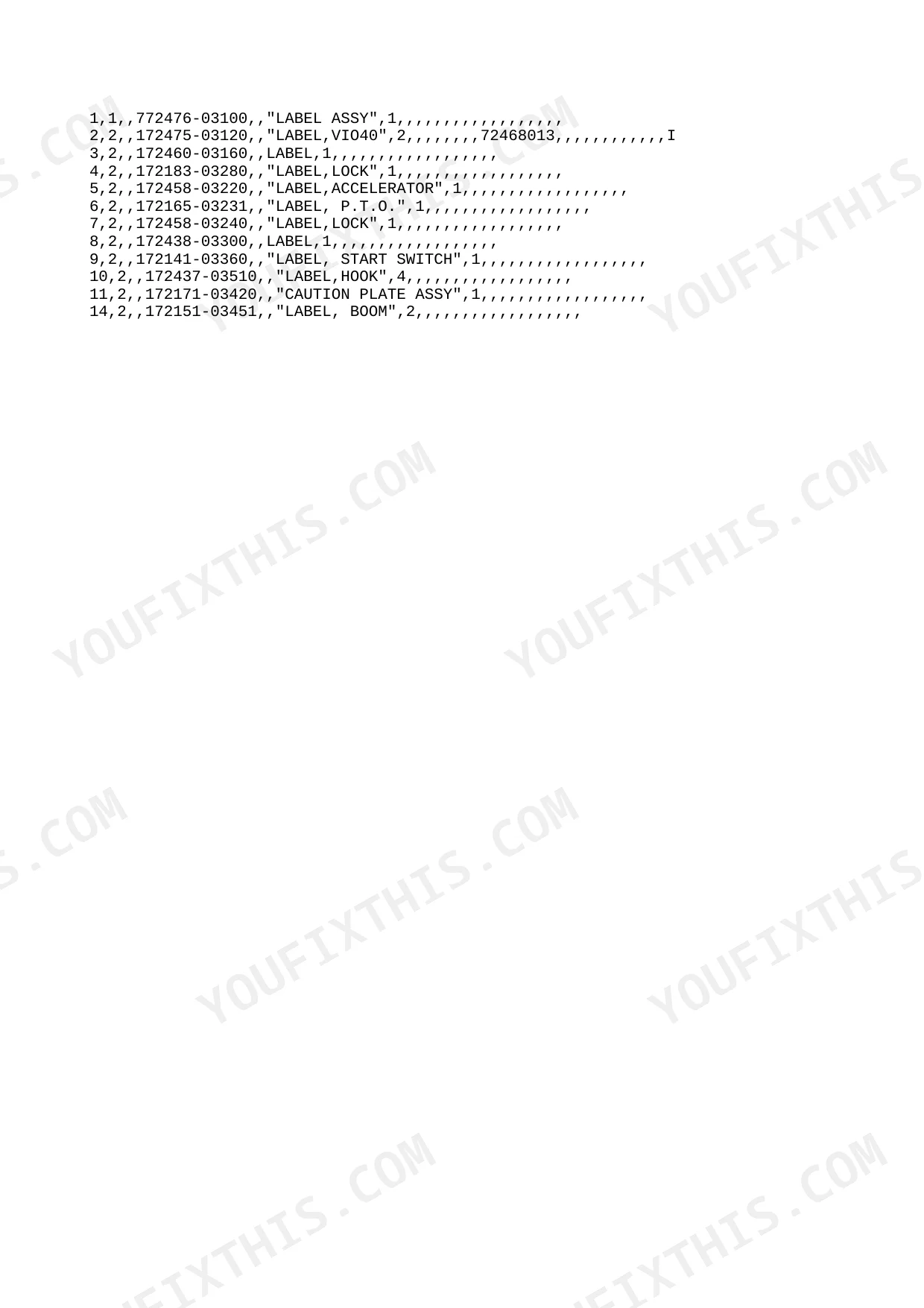
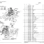
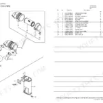
| Silenser & Air Cleaner | 5-18 | Figure Index, Hydraulic Section, Main Parts, Label, Wiring Diagram, Fan |
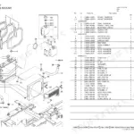
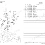
| Work Lamp | 19-34 | Fuel Tank & Fuel Pipe, Engine Mount, Accelerator, Radiator & Mount, Electric Part (Wiring), Battery, Electric Part (Equipment) |
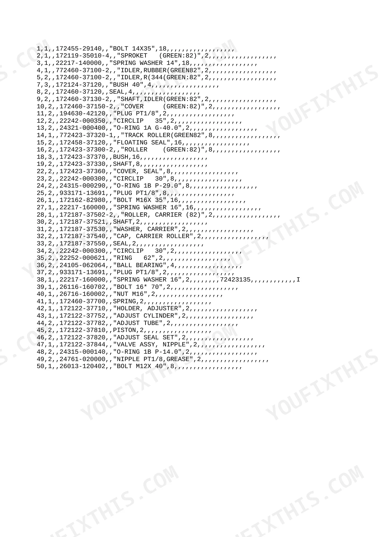
| Control Equipment (Low-High Pedal) | 35-50 | Control Equipment (Lock Lever & Stand) Left, Crawler, Roller & Adjust, Control Equipment (Lock Lever & Stand) Right, Control Equipment (Blade Lever), Control Equipment (Travel Lever), Control Equipment (Swing Pedal) |
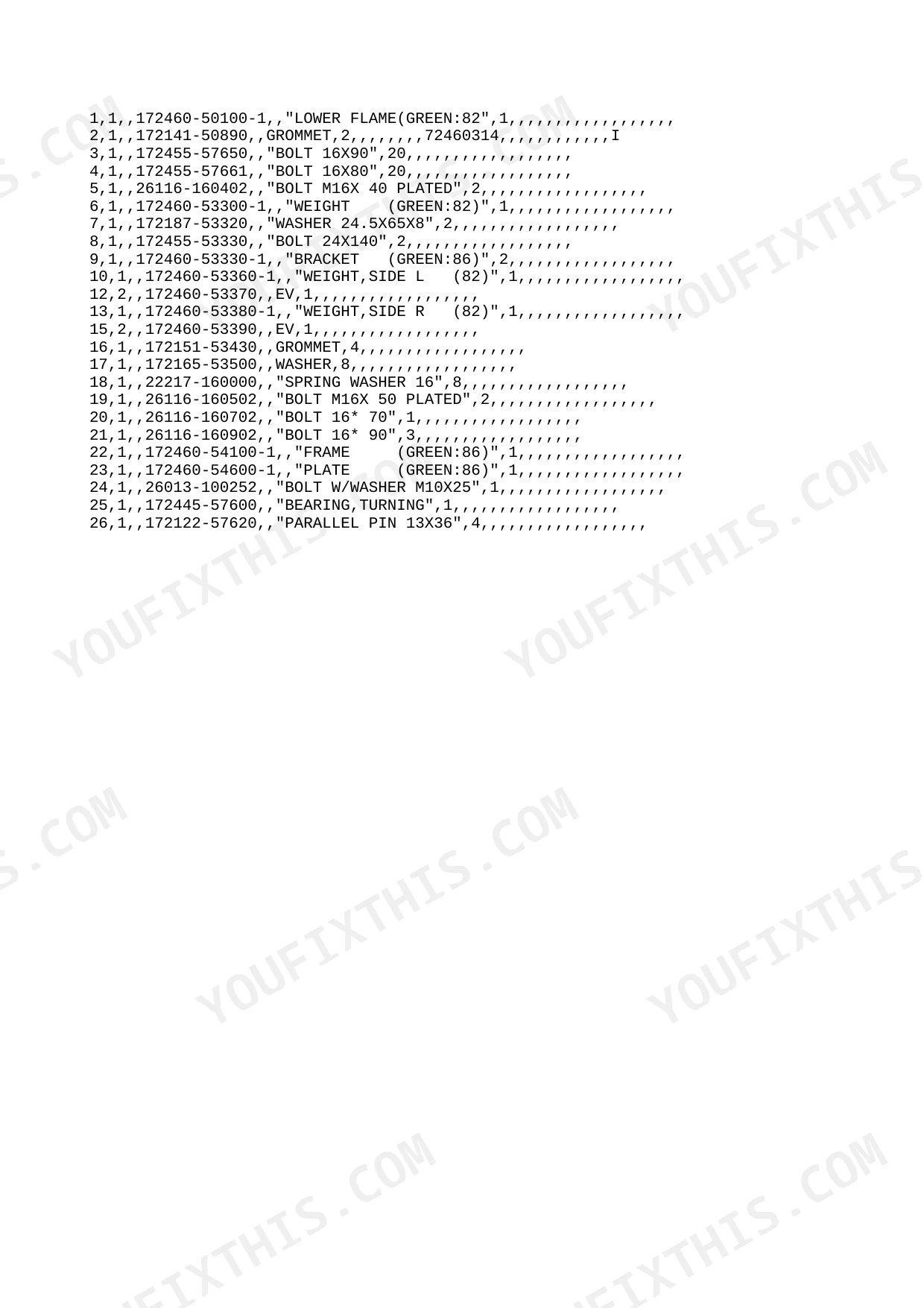
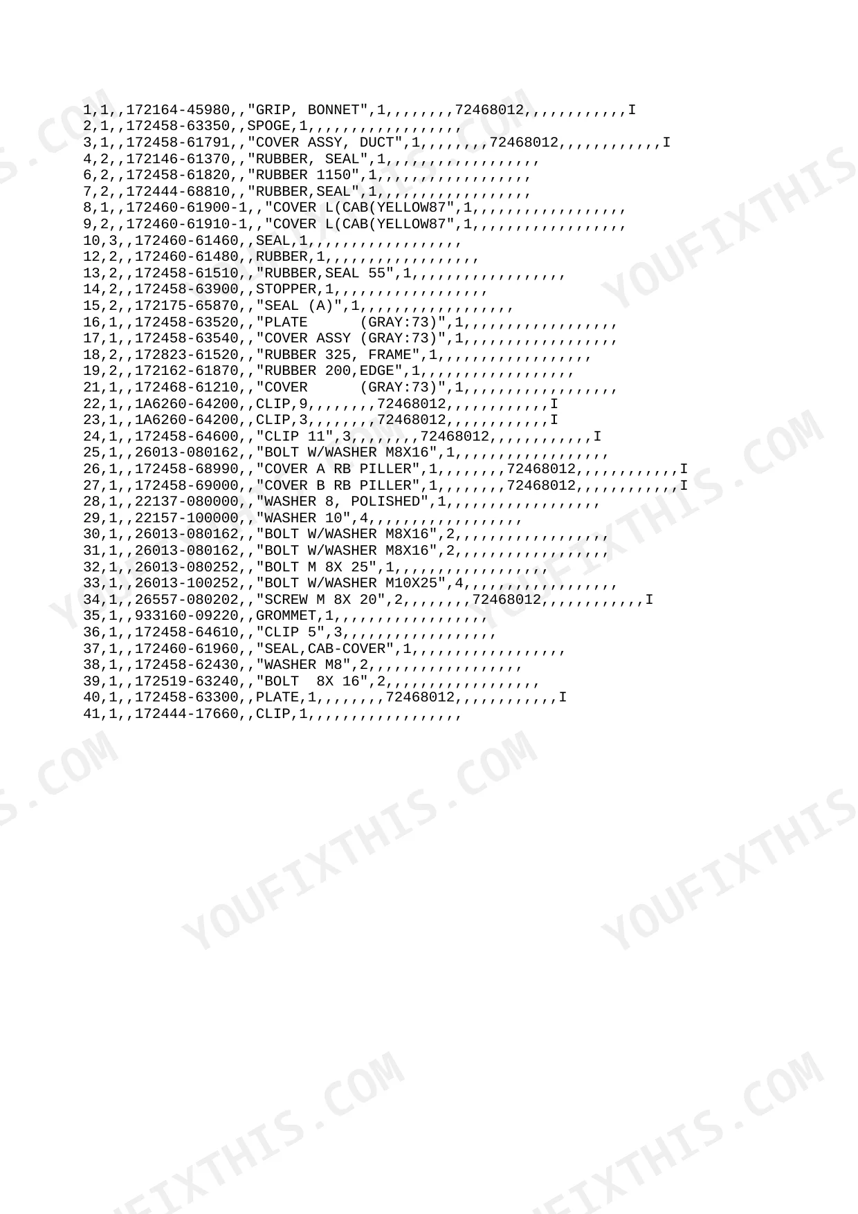
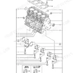
| Boom Cylinder | 51-72 | Cover (Cabin), Frame & Turning Bearing, Control Equipment (P.T.O. Pedal), Cover (Frame), Seat Mount, Step & Instrument Panel, Canopy Mount, Bonnet |
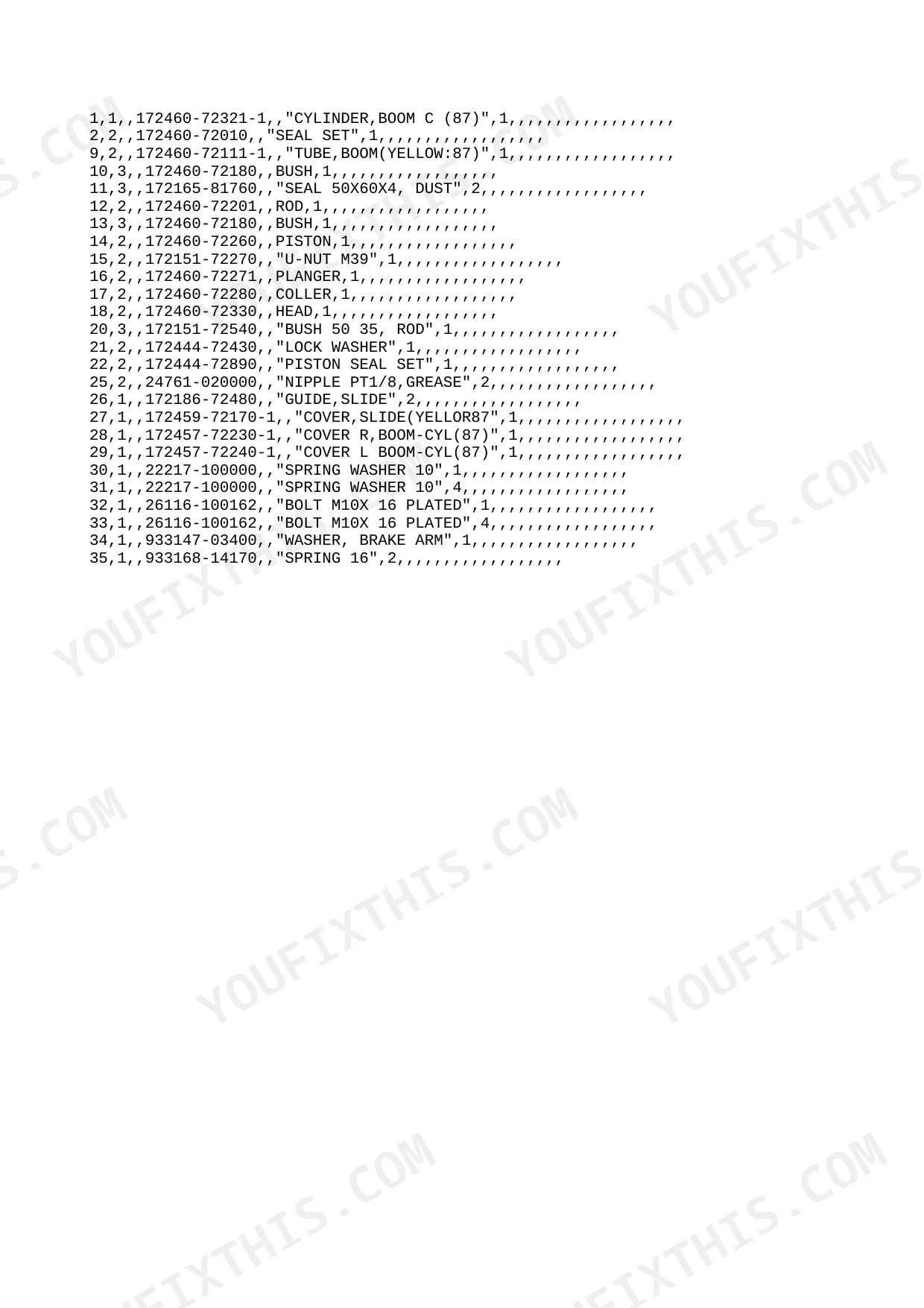
| Control Valve (P Port) | 73-88 | Blade Cylinder, Bucket Cylinder, Arm Cylinder, Swing Cylinder, Turning Motor, Travel Motor, Swivel Joint |
| Hyd. Oil Piping (Pump-Valve-Motor) | 89-104 | Control Valve (Turning & Blade), Control Valve (Arm & Swing), Control Valve (Travel & P.T.O.), Control Valve (Boom & Bucket), Hyd. Oil Tank, Remote Control Valve, Hyd. Oil Piping (Tank-Pump-Valve) |
| Greasing | 105-120 | Hyd. Oil Piping (Boom), Hyd. Oil Piping (Return), Hyd. Oil Piping (Valve-Swivel-Swing), Hyd. Oil Piping (Travel), Control Piping (Pump-Remo.-Con.V.-Return), Hyd. Oil Piping (P.T.O.), Control Piping (Remo.-Con.V.-C-V.) |
| Blade | 121-131 | Arm & Bucket Link, Boom & Boom Bracket, Bucket Pin |
Quick Reference Specifications
| Specification | Value | Page |
|---|---|---|
| Slow Blow Fuse Rating | 50A | p. 29 |
| Bulb Specification (T6.5) | 13.5V-2W | p. 31 |
| Bulb Specification (T5) | 14V-2W | p. 31 |
| Work Lamp Bulb Rating | 12V 55W | p. 33 |
| Hyd. Oil Tank O-Ring Dimension | 105.0 | p. 100 |
Yanmar Vio40-2 Common Problems This Manual Covers
Cab work lights fail to turn on during low light operation or early morning shifts.
Review the cab and interior parts diagram to locate the exterior lamp housings and mounting hardware. Find the correct replacement bulb part numbers. Order the exact 12V 55W work lamp bulb specified on page 33 to ensure proper fitment and safe nighttime illumination.
Manual Section: Electrical System Diagnostic Aid (Wiring Diagram)Frequently Asked Questions
What are the replacement specifications for battery?
The replacement specification for the battery is identified by part number 172460-16130. This part number can be found in the 'Battery' section of the manual on page 27. No further detailed specifications such as voltage or cold cranking amps are provided in this parts catalog. p. 27
How do you fix yanmar Vio40-2 intermittent hydraulic function loss after warm up or operating the safety lever?
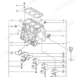
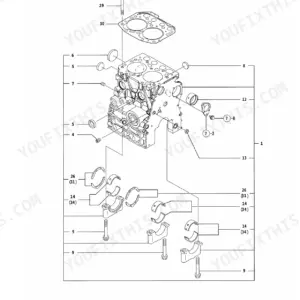
Inspect the hydraulic pump exploded view. Locate the main pump components and joint parts in the diagram. Check the tank connections and order a replacement 105.0 mm hydraulic oil tank O-ring shown on page 100 if the existing seal shows signs of degradation.
How do you fix engine cranks but will not start or stalls out shortly after dropping to low idle?
Check the electrical circuit layout to find the main wiring connections and harness routing. Locate the main fuse block assembly in the diagram. Replace the blown 50A slow blow fuse identified on page 29 to restore power to the primary ignition and starter circuits.
How do you fix dozer blade control feels sloppy and tracks wear unevenly during normal forward and reverse operation?
Inspect the drivetrain parts diagram to identify the correct track roller assembly components. Locate the blade control linkage assembly in the parts list. Replace the worn 3X32 blade lever spring pin identified on page 45 to restore tight and accurate control lever movement.
What format is this manual in?
You get a 131-page searchable PDF that downloads instantly after checkout. Open it on your laptop, tablet, or phone, and bring it right to the shop floor.
Can I print specific sections of this Yanmar Vio40-2 Parts Catalog?
Yes, print as many copies as you want, and there are no restrictions. Many mechanics print the section they need and bring it to the shop floor.
Reviews
There are no reviews yet.