


Need a part number you can actually order? This Kubota L2900DT Parts Catalog is built for one job: matching the exact factory number to your tractor on the first try. Each section opens with an exploded-view diagram beside a numbered parts list, giving you REF numbers, part numbers, quantities, and country-code applicability so the fit is never a guess. The 333 indexed pages run from engine internals (crankcase through injection pump) to full transmission and PTO assemblies, hydraulic pump and control valve component internals, plus steering, brakes, chassis, and ROPS. Shim figures sit inline with their assemblies: injection shims at 0.20, 0.25, and 0.30mm, and the hydraulic control valve shim at 0.40mm. Skip the microfiche. Jump to any system by bookmark, read the number off your phone, and order.
What's Inside This Kubota L2900DT Parts Manual
| System | Pages | Key Topics |
|---|---|---|
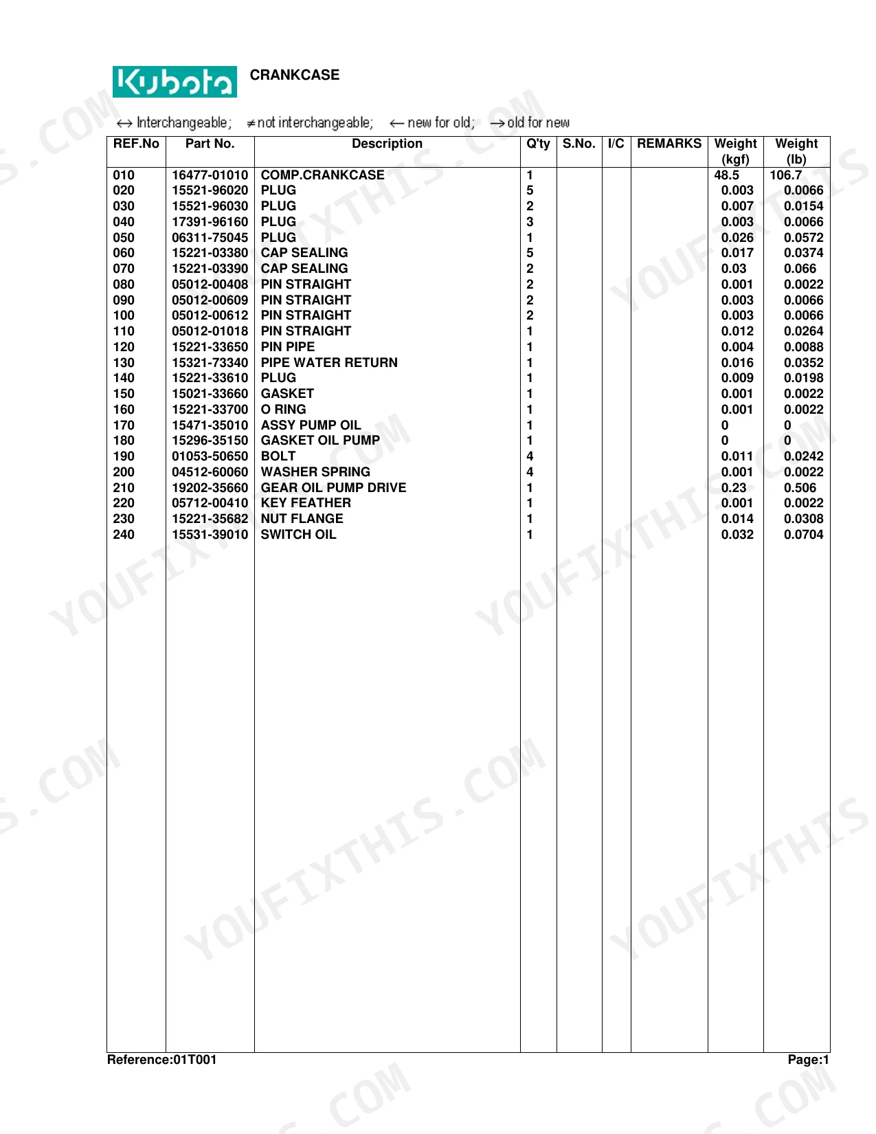
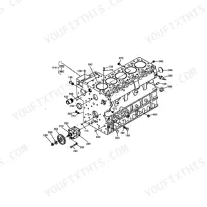
| Crankcase | 7-8 | CRANKCASE Diagram, CRANKCASE Parts List, Table of Crankcase Parts |
| Oil Pan | 9-10 | OIL PAN Diagram, OIL PAN Parts List, Table of Oil Pan Parts |
| Piston and Crankshaft | 11-12 | Piston And Crankshaft Diagram, Piston And Crankshaft Parts List, Table of Piston and Crankshaft Parts |
| Main Bearing Case | 13-14 | Main Bearing Case Diagram, Main Bearing Case Parts List, Table of Main Bearing Case Parts |
| Flywheel [W/O Ind-Pto] | 15-17 | Flywheel [w/o Ind-pto] Diagram, FLYWHEEL [W/O IND-PTO] Detail View, Flywheel [w/o Ind-pto] Parts List, Table of Flywheel [W/O IND-PTO] Parts |
| Flywheel [With Ind-Pto] | 18-20 | Flywheel [with Ind-pto] Diagram, Flywheel [with Ind-pto] Detail View, Flywheel [with Ind-pto] Parts List, Table of Flywheel [WITH IND-PTO] Parts |
| Cylinder Head | 21-22 | CYLINDER HEAD Diagram, CYLINDER HEAD Parts List, Table of Cylinder Head Parts |
| Valve and Rocker Arm | 23-25 | Valve And Rocker Arm Diagram, Valve And Rocker Arm Detail View, Valve And Rocker Arm Parts List, Table of Valve and Rocker Arm Parts |
| Nozzle Holder/Glow Plug | 26-30 | Nozzle Holder [Component Parts] |
| Cylinder Head Cover | 31-32 | Cylinder Head Cover Diagram, Cylinder Head Cover Parts List, Table of Cylinder Head Cover Parts |
| Inlet Manifold | 33-34 | INLET MANIFOLD Diagram, INLET MANIFOLD Parts List, Table of Inlet Manifold Parts |
| Camshaft | 35-36 | CAMSHAFT Diagram, CAMSHAFT Parts List, Table of Camshaft Parts |
| Gear Case | 37-38 | GEAR CASE Diagram, GEAR CASE Parts List, Table of Gear Case Parts |
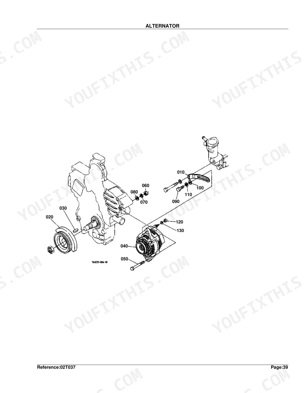
| Water Pump | 39-40 | WATER PUMP Diagram, WATER PUMP Parts List, Table of Water Pump Parts |
| Water Flange and Thermostat | 41-42 | Water Flange And Thermostat Diagram, Water Flange And Thermostat Parts List, Table of Water Flange and Thermostat Parts |
| Fuel Camshaft | 43-44 | FUEL CAMSHAFT Diagram, FUEL CAMSHAFT Parts List, Table of Fuel Camshaft Parts |
| Injection Pump | 45-46 | INJECTION PUMP Diagram, INJECTION PUMP Parts List, Table of Injection Pump Parts |
| Injection Pump [Component Parts] | 47-48 | Injection Pump [component Parts] Diagram, Injection Pump [component Parts] Parts List, Table of Injection Pump Component Parts |
| Engine Stop Lever | 49-50 | Engine Stop Lever Diagram, Engine Stop Lever Parts List, Table of Engine Stop Lever Parts |
| Speed Control Plate | 51-52 | Speed Control Plate Diagram, Speed Control Plate Parts List, Table of Speed Control Plate Parts |
| Governor | 53-54 | GOVERNOR Diagram, GOVERNOR Parts List, Table of Governor Parts |
| Upper Gasket Kit | 55-56 | Upper Gasket Kit Diagram, UPPER GASKET KIT Parts List, Table of Upper Gasket Kit Parts |
| Lower Gasket Kit | 57-58 | Lower Gasket Kit Diagram, LOWER GASKET KIT Parts List, Table of Lower Gasket Kit Parts |
| Air Cleaner | 59-60 | AIR CLEANER Diagram, AIR CLEANER Parts List, Table of Air Cleaner Parts |
| Double Air Cleaner [Option] | 61-62 | Double Air Cleaner [option] Diagram, Double Air Cleaner [option] Parts List, Table of Double Air Cleaner [OPTION] Parts |
| Exhaust Manifold and Muffler | 63-64 | Exhaust Manifold And Muffler Diagram, Exhaust Manifold And Muffler Parts List, Table of Exhaust Manifold and Muffler Parts |
| Stop Solenoid and Engine Stop Wire | 65-67 | Stop Solenoid And Engine Stop Wire Diagram, Stop Solenoid And Engine Stop Wire Parts List |
| Accelerator Lever | 68-69 | Accelerator Lever Diagram, Accelerator Lever Parts List, Table of Accelerator Lever Parts |
| Accelerator Linkage | 70-71 | Accelerator Linkage Diagram, Accelerator Linkage Parts List, Table of Accelerator Linkage Parts |
| Accelerator Rod | 72-73 | Accelerator Rod Diagram, ACCELERATOR ROD Parts List, Table of Accelerator Rod Parts |
| Fuel Tank | 74-75 | FUEL TANK Diagram, FUEL TANK Parts List, Table of Fuel Tank Parts |
| Fuel Pipe and Fuel Filter | 76-77 | Fuel Pipe And Fuel Filter Diagram, Fuel Pipe And Fuel Filter Parts List, Table of Fuel Pipe and Fuel Filter Parts |
| Fuel Filter [Component Parts] | 78-79 | Fuel Filter [component Parts] Diagram, Fuel Filter [component Parts] Parts List, Table of Fuel Filter Component Parts |
| Fan | 80-81 | FAN Diagram, FAN Parts List, Table of Fan Parts |
| Water Pipe | 82-83 | WATER PIPE Diagram, WATER PIPE Parts List, Table of Water Pipe Parts |
| Radiator | 84-85 | RADIATOR Diagram, RADIATOR Parts List, Table of Radiator Parts |
| Reserve Tank | 86-87 | RESERVE TANK Diagram, RESERVE TANK Parts List, Table of Reserve Tank Parts |
| Alternator | 88-90 | ALTERNATOR Diagram, ALTERNATOR Detail View, ALTERNATOR Parts List, Table of Alternator Parts |
| Alternator [Component Parts] | 91-92 | Alternator [component Parts] Diagram, Alternator [component Parts] Parts List, Table of Alternator Component Parts |
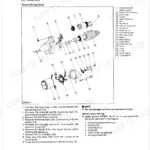
| Starter | 93-94 | STARTER Diagram, STARTER Parts List, Table of Starter Parts |
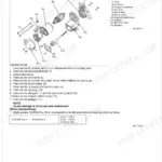
| Starter [Component Parts] | 95-96 | Starter [component Parts] Diagram, Starter [component Parts] Parts List, Table of Starter Component Parts |
| Battery | 97-98 | BATTERY Diagram, BATTERY Parts List, Table of Battery Parts |
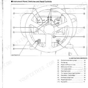
| Switch | 99-100 | SWITCH Diagram, SWITCH Parts List, Table of Switch Parts |
| Panel Board | 101-102 | PANEL BOARD Diagram, PANEL BOARD Parts List, Table of Panel Board Parts |
| Panel Board [Component Parts] | 103-104 | Panel Board [component Parts] Diagram, Panel Board [component Parts] Parts List, Table of Panel Board Component Parts |
| Light | 105-106 | LIGHT Diagram, LIGHT Parts List, Table of Light Parts |
| Electrical Wiring | 107-108 | Electrical Wiring Diagram, Electrical Wiring Parts List, Table of Electrical Wiring Parts |
| Clutch | 109-110 | CLUTCH Diagram, CLUTCH Parts List, Table of Clutch Parts |
| Clutch Lever | 111-112 | CLUTCH LEVER Diagram, CLUTCH LEVER Parts List, Table of Clutch Lever Parts |
| Clutch Pedal | 113-114 | CLUTCH PEDAL Diagram, CLUTCH PEDAL Detail View, CLUTCH PEDAL Parts List, Table of Clutch Pedal Parts |
| Clutch Housing [Manual T/M Type] | 115-117 | Clutch Housing [manual T/m Type] Diagram, Clutch Housing [manual T/m Type] Detail View, Clutch Housing [manual T/m Type] Parts List |
| Mid Case [Manual T/M Type] [With Ind-Pto] | 118-120 | Case Mid, Holder Bearing, Piston, Cover, Spring, Seal Piston, O Ring, Cir Clip Internal |
| Transmission Case | 121-122 | Transmission Case Diagram, Transmission Case Parts List, Table of Transmission Case Parts |
| Main Shaft [With Ind-Pto] | 123-124 | Main Shaft [with Ind-pto] Diagram, Main Shaft [with Ind-pto] Parts List, Table of Main Shaft [With Ind-PTO] Parts |
| Countershaft | 125-126 | COUNTERSHAFT Diagram, COUNTERSHAFT Parts List, Table of Countershaft Parts |
| Shuttle Shaft [Manual T/M Type] | 127-128 | Shuttle Shaft [manual T/m Type] Diagram, Shuttle Shaft [manual T/m Type] Parts List |
| Range Gear Shaft [Manual T/M Type] | 129-130 | Range Gear Shaft [manual T/m Type] Diagram, Range Gear Shaft [manual T/m Type] Parts List |
| PTO Countershaft [With Ind-Pto] | 131-132 | Pto Countershaft [with Ind-pto] Diagram, Pto Countershaft [with Ind-pto] Parts List |
| PTO Clutch [With Ind-Pto] | 133-134 | Pto Clutch [with Ind-pto] Diagram, Pto Clutch [with Ind-pto] Parts List, Table of PTO Clutch [With Ind-PTO] Parts |
| PTO Shaft [W/O Mid-Pto] | 135-137 | Pto Shaft [w/o Mid-pto] Diagram, PTO SHAFT [W/O MID-PTO] Detail View, Pto Shaft [w/o Mid-pto] Parts List, Table of PTO Shaft [W/O Mid-PTO] Parts |
| PTO Shaft [With Mid-Pto] | 138-140 | Pto Shaft [with Mid-pto] Diagram, Pto Shaft [with Mid-pto] Detail View, Pto Shaft [with Mid-pto] Parts List, Table of PTO Shaft [With Mid-PTO] Parts |
| Mid PTO [With Mid-Pto] | 141-142 | Mid Pto [with Mid-pto] Diagram, Mid Pto [with Mid-pto] Parts List, Table of Mid PTO [With Mid-PTO] Parts |
| Main Gear Shift Lever [Manual T/M Type] | 143-145 | Assy Bracket, Bush, Bolt Flange, Lever Main Shift, Grip Lever, U Joint, Pin Joint, Washer Plain |
| Main Gear Shift Fork [Manual T/M Type] | 146-147 | Fork Main Shift, Fork Shift, Rod Fork, Pin Spring, Ball, Bolt, Washer Spring, Spring |
| Shuttle Shift Lever | 148-150 | Shuttle Shift Lever Diagram, Shuttle Shift Lever Detail View, Shuttle Shift Lever Parts List, Table of Shuttle Shift Lever Parts |
| Shuttle Shift Fork [Manual T/M Type] | 151-152 | Fork Shuttle Shift, Bolt Reamer, Washer, Rod Fork, Spring, Ball, Arm Shuttle Shift, O Ring |
| Range Gear Shift Lever [Manual T/M Type] [W/O Creep] | 153-154 | Range Gear Shift Lever, Pin Spring, Rod, Washer Plain, Pin Split, Pin Snap, Bush, Grip Lever |
| Range Gear Shift Lever/Creep Gear Shift Lever [Manual T/M Type] [With Creep] | 155-157 | Range Gear Shift Lever, Creep Gear Shift Lever, Shaft Fulcrum, Circlip External, Shim, Rod Creep, Assy Lever Creep |
| Range Gear Shift Fork and Creep Gear Shift Fork [Manual T/M Type] | 158-159 | Range Gear Shift Fork, Creep Gear Shift Fork, Fork Range Shift, Rod Fork, Spring, Ball, Arm Range Shift, O Ring |
| Mid PTO Shift Lever [With Mid-Pto] | 160-161 | Mid Pto Shift Lever [with Mid-pto] Diagram, Mid Pto Shift Lever [with Mid-pto] Parts List |
| PTO Clutch Control Lever [With Ind-Pto] | 162-164 | PTO Clutch Control Lever, Assy Valve I-PTO, Pipe Hydraulic, Wire PTO, Grommet, Bracket I-PTO Lever, Lever I-PTO, Grip PTO Lever |
| PTO Gear Shift Lever [W/O Ind-Pto] | 165-167 | Pto Gear Shift Lever [w/o Ind-pto] Diagram, Pto Gear Shift Lever [w/o Ind-pto] Parts List |
| Spiral Bevel Pinion [W/O Creep] | 168-169 | Spiral Bevel Pinion [w/o Creep] Diagram, Spiral Bevel Pinion [w/o Creep] Parts List |
| Spiral Bevel Pinion and Creep [With Creep] | 170-171 | Spiral Bevel Pinion, Creep, Gear 4WD, Circlip External, Gear-shaft, Nut, Case, Bearing Taper-roller |
| Rear Differential | 172-173 | Rear Differential Diagram, Rear Differential Parts List, Table of Rear Differential Parts |
| Defferential Lock Shift Fork | 174-175 | Defferential Lock Shift Fork Diagram, Defferential Lock Shift Fork Parts List, Table of Defferential Lock Shift Fork Parts |
| Rear Axle | 176-177 | REAR AXLE Diagram, REAR AXLE Parts List, Table of Rear Axle Parts |
| Rear Wheel (11.2-24) | 178-179 | REAR WHEEL (11.2-24) Diagram, REAR WHEEL (11.2-24) Parts List, Table of Rear Wheel (11.2-24) Parts |
| Rear Wheel (12.4-24) | 180-181 | REAR WHEEL (12.4-24) Diagram, REAR WHEEL (12.4-24) Parts List, Table of Rear Wheel (12.4-24) Parts |
| Rear Wheel (420/70-24) | 182-183 | REAR WHEEL (420/70-24) Diagram, REAR WHEEL (420/70-24) Parts List, Table of Rear Wheel (420/70-24) Parts |
| Rear Wheel (13.6-16) | 184-185 | REAR WHEEL (13.6-16) Diagram, REAR WHEEL (13.6-16) Parts List, Table of Rear Wheel (13.6-16) Parts |
| Rear Wheel (41X14.00-20) | 186-187 | REAR WHEEL (41X14.00-20) Diagram, REAR WHEEL (41X14.00-20) Parts List, Table of Rear Wheel (41X14.00-20) Parts |
| Rear Wheel (21.5L-16.1) | 188-189 | REAR WHEEL (21.5L-16.1) Diagram, REAR WHEEL (21.5L-16.1) Parts List, Table of Rear Wheel (21.5L-16.1) Parts |
| Rear Wheel (355/80-D20) | 190-191 | REAR WHEEL (355/80-D20) Diagram, REAR WHEEL (355/80-D20) Parts List, Table of Rear Wheel (355/80-D20) Parts |
| Brake | 192-193 | BRAKE Diagram, BRAKE Parts List, Table of Brake Parts |
| Brake Pedal | 194-196 | BRAKE PEDAL Diagram, BRAKE PEDAL Detail View, BRAKE PEDAL Parts List, Table of Brake Pedal Parts |
| Brake Rod 1 | 197-198 | BRAKE ROD 1 Diagram, BRAKE ROD 1 Parts List, Table of Brake Rod 1 Parts |
| Brake Rod 2 | 199-200 | BRAKE ROD 2 Diagram, BRAKE ROD 2 Parts List, Table of Brake Rod 2 Parts |
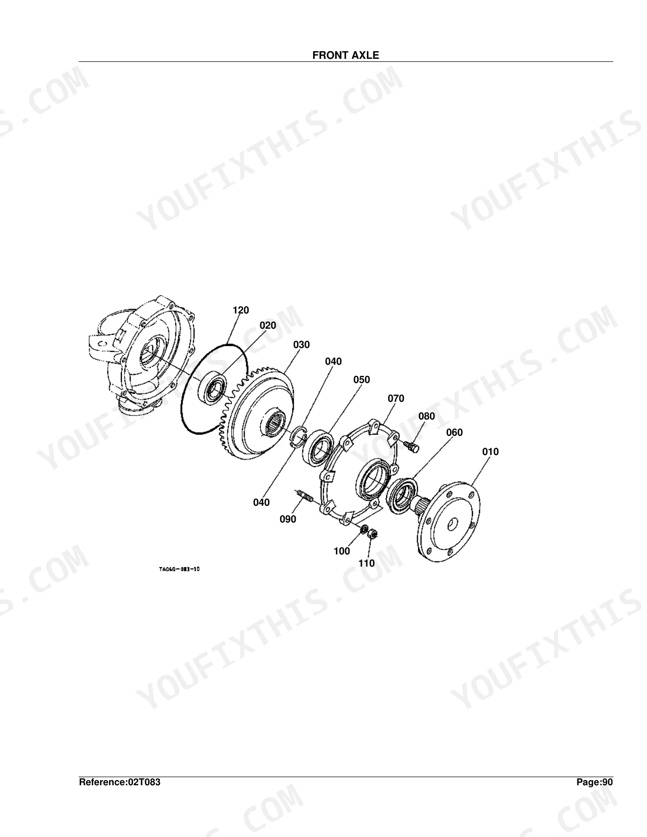
| Front Axle | 201-202 | FRONT AXLE Diagram, FRONT AXLE Parts List, Table of Front Axle Parts |
| Front Axle Case | 203-205 | FRONT AXLE CASE Diagram, FRONT AXLE CASE Detail View, FRONT AXLE CASE Parts List, Table of Front Axle Case Parts |
| Differential Gear Shaft | 206-207 | Differential Gear Shaft Diagram, Differential Gear Shaft Parts List, Table of Differential Gear Shaft Parts |
| Front Differential Case | 208-210 | Front Differential Case Diagram, Front Differential Case Detail View, Front Differential Case Parts List, Table of Front Differential Case Parts |
| Front Differential | 211-212 | Front Differential Diagram, Front Differential Parts List, Table of Front Differential Parts |
| Propeller Shaft | 213-214 | Propeller Shaft Diagram, PROPELLER SHAFT Parts List, Table of Propeller Shaft Parts |
| Front Wheel Drive Shaft | 215-216 | Front Wheel Drive Shaft Diagram, Front Wheel Drive Shaft Parts List, Table of Front Wheel Drive Shaft Parts |
| Front Wheel Drive Lever | 217-218 | Front Wheel Drive Lever Diagram, Front Wheel Drive Lever Parts List, Table of Front Wheel Drive Lever Parts |
| Front Wheel (7.2-16) | 219-220 | FRONT WHEEL (7.2-16) Diagram, FRONT WHEEL (7.2-16) Parts List, Table of Front Wheel (7.2-16) Parts |
| Front Wheel (10-16.5) | 221-222 | FRONT WHEEL (10-16.5) Diagram, FRONT WHEEL (10-16.5) Parts List, Table of Front Wheel (10-16.5) Parts |
| Front Wheel (25*8.50-14) | 223-224 | FRONT WHEEL (25*8.50-14) Diagram, FRONT WHEEL (25*8.50-14) Parts List, Table of Front Wheel (25*8.50-14) Parts |
| Front Wheel (27*8.50-15) | 225-226 | FRONT WHEEL (27*8.50-15) Diagram, FRONT WHEEL (27*8.50-15) Parts List, Table of Front Wheel (27*8.50-15) Parts |
| Front Wheel (27*10.50-15) | 227-228 | FRONT WHEEL (27*10.50-15) Diagram, FRONT WHEEL (27*10.50-15) Parts List, Table of Front Wheel (27*10.50-15) Parts |
| Front Wheel (29*12.50-15) | 229-230 | FRONT WHEEL (29*12.50-15) Diagram, FRONT WHEEL (29*12.50-15) Parts List, Table of Front Wheel (29*12.50-15) Parts |
| Front Axle Frame [4Wd] | 231-233 | Front Axle Frame [4WD] Diagram, FRONT AXLE FRAME [4WD] Detail View, Front Axle Frame [4WD] Parts List, Table of Front Axle Frame [4WD] Parts |
| Steering Linkage [4Wd] | 234-235 | Steering Linkage [4WD] Diagram, Steering Linkage [4WD] Parts List, Table of Steering Linkage [4WD] Parts |
| Steering Cylinder | 236-238 | Steering Cylinder Diagram, STEERING CYLINDER Detail View, Steering Cylinder Parts List, Table of Steering Cylinder Parts |
| Steering Cylinder [Component Parts] | 239-241 | Steering Cylinder [component Parts] Diagram, Table of Steering Cylinder Component Parts |
| Steering Controller | 242-243 | Steering Controller Diagram, Steering Controller Parts List, Table of Steering Controller Parts |
| Steering Handle | 244-245 | Steering Handle Diagram, STEERING HANDLE Parts List, Table of Steering Handle Parts |
| Hydraulic Oil Line (Ps) | 246-248 | Hydraulic Oil Line (ps) Diagram, Hydraulic Oil Line (ps) Detail View, Hydraulic Oil Line (ps) Parts List, Table of Hydraulic Oil Line (PS) Parts |
| Regulator Valve | 249-250 | Regulator Valve Diagram, REGULATOR VALVE Parts List, Table of Regulator Valve Parts |
| PTO Hydraulic Oil Line [With Ind-Pto] [Manual T/M Type] | 251-252 | PTO Hydraulic Oil Line, Assy Bolt Orifice, Gasket, Comp.Pipe I-PTO, Bolt Joint, Clamp, Pipe Rubber |
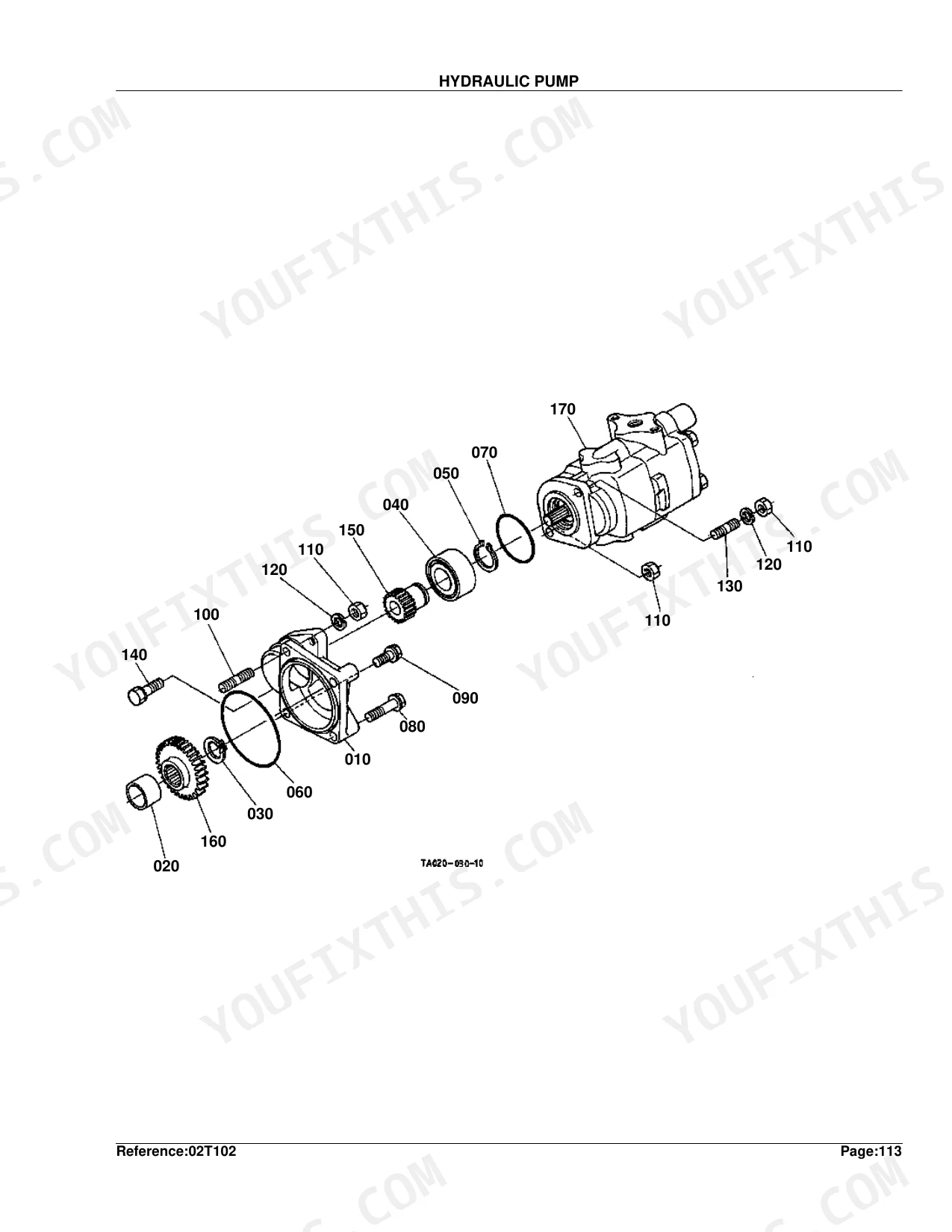
| Hydraulic Pump | 253-254 | HYDRAULIC PUMP Diagram, HYDRAULIC PUMP Parts List, Table of Hydraulic Pump Parts |
| Hydraulic Pump [Component Parts] | 255-256 | Hydraulic Pump [component Parts] Diagram, Hydraulic Pump [component Parts] Parts List, Table of Hydraulic Pump Component Parts |
| Hydraulic Oil Line (Inlet) | 257-259 | Hydraulic Oil Line (inlet) Diagram, Hydraulic Oil Line (inlet) Detail View, Hydraulic Oil Line (inlet) Parts List, Table of Hydraulic Oil Line (Inlet) Parts |
| Hydraulic Oil Line (Delivery) | 260-261 | Hydraulic Oil Line (delivery) Diagram, Hydraulic Oil Line (delivery) Parts List, Table of Hydraulic Oil Line (Delivery) Parts |
| Hydraulic Outlet Block | 262-263 | Hydraulic Outlet Block Diagram, Hydraulic Outlet Block Parts List, Table of Hydraulic Outlet Block Parts |
| Hydraulic Cylinder | 264-266 | Hydraulic Cylinder Diagram, Hydraulic Cylinder Detail View, Hydraulic Cylinder Parts List, Table of Hydraulic Cylinder Parts |
| Lift Arm | 267-268 | LIFT ARM Diagram, LIFT ARM Parts List, Table of Lift Arm Parts |
| Control Valve | 269-271 | CONTROL VALVE Diagram, CONTROL VALVE Detail View, CONTROL VALVE Parts List, Table of Control Valve Parts |
| Control Valve [Component Parts] | 272-273 | Control Valve [component Parts] Diagram, Control Valve [component Parts] Parts List, Table of Control Valve Component Parts |
| Feed Back Lever | 274-275 | FEED BACK LEVER Diagram, FEED BACK LEVER Parts List, Table of Feed Back Lever Parts |
| Position Control Lever | 276-278 | Position Control Lever Diagram, Position Control Lever Detail View, Position Control Lever Parts List, Table of Position Control Lever Parts |
| Draft and Position Control Lever 1 [Option] | 279-280 | Draft And Position Control Lever, Link Control, Pin Spring, Shaft Draft, Spring Plate, Link Draft, Circlip External, Rod Control |
| Draft and Position Control Lever 2 [Option] | 281-282 | Draft And Position Control Lever, Stay, Bolt, Bush, Shaft Draft, Gasket, Washer Plain, Spring Plate |
| Top Link Holder [Option] | 283-284 | Top Link Holder [option] Diagram, Top Link Holder [option] Parts List, Table of Top Link Holder [Option] Parts |
| Drawbar and PTO Protector | 285-287 | Drawbar And Pto Protector Diagram, Drawbar And Pto Protector Detail View, Drawbar And Pto Protector Parts List, Table of Drawbar and PTO Protector Parts |
| Swinging Drawbar and Clevis Drawbar [Option] | 288-289 | Frame Swing Drawbar, Bolt, Washer Spring, Pin Joint, Pin Snap, Manual Assembly, Drawbar, Hitch Drawbar |
| Remote Control Valve Lever 1 [Option] | 290-291 | Assy Valve Aux.con., Cover Aux.cont.valve, Assy Pipe Cont.valve, Pipe Return, Lever Aux.con.valve, Tube Lever, Grip Lever, Stay Aux.cont.valve |
| Remote Control Valve Lever 2 [Option] | 292-293 | Assy Valve Aux.con., Cover Aux.cont.valve, Assy Pipe Cont.valve, Lever Aux.con.valve, Tube Lever, Grip Lever, Stay Aux.cont.valve, Mark Aux.cont.valve |
| Remote Control Valve Lever 3 [Option] | 294-295 | Remote Control Valve Lever 3, Assy Valve Aux.con., Cover Aux.cont.valve, Assy Pipe Cont.valve, Pipe Return, Lever Aux.con.valve, Tube Lever, Grip Lever |
| Remote Control Valve Coupler 1 [Option] | 296-297 | Adapter, Hose Aux.cont.valve, Assy Coupler Female, Plug Coupler, Support Coupler, Cir Clip Internal, Washer Spring, Assy Coupler Male |
| Remote Control Valve Coupler 2 [Option] | 298-299 | Remote Control Valve Coupler, Adapter, O Ring, Hose Aux.cont.valve, Assy Coupler Female, Plug Coupler, Support Coupler, Cir Clip Internal |
| Remote Control Valve Coupler 3 [Option] | 300-301 | Remote Control Valve Coupler, Adapter, O Ring, Hose Aux.cont.valve, Assy Coupler Female, Plug Coupler, Support Coupler, Cir Clip Internal |
| 3-Point Linkage 1 (Lower Link) | 302-303 | 3-POINT Linkage 1 (lower Link) Diagram, 3-POINT Linkage 1 (lower Link) Parts List, Table of 3-Point Linkage 1 (Lower Link) Parts |
| 3-Point Linkage 2 (Lift Rod) | 304-305 | 3-POINT Linkage 2 (lift Rod) Diagram, 3-POINT Linkage 2 (lift Rod) Parts List, Table of 3-Point Linkage 2 (Lift Rod) Parts |
| Front Grille | 306-308 | FRONT GRILLE Diagram, FRONT GRILLE Detail View, FRONT GRILLE Parts List, Table of Front Grille Parts |
| Front Grille Support | 309-310 | Front Grille Support Diagram, Front Grille Support Parts List, Table of Front Grille Support Parts |
| Hood (Bonnet) | 311-313 | HOOD (BONNET) Diagram, HOOD (BONNET) Detail View, HOOD (BONNET) Parts List, Table of Hood (Bonnet) Parts |
| Side Cover | 314-316 | SIDE COVER Diagram, SIDE COVER Detail View, SIDE COVER Parts List, Table of Side Cover Parts |
| Side Cover Lower | 317-318 | Side Cover Lower Diagram, SIDE COVER LOWER Parts List, Table of Side Cover Lower Parts |
| Shutter Plate | 319-321 | SHUTTER PLATE Diagram, SHUTTER PLATE Detail View, SHUTTER PLATE Parts List, Table of Shutter Plate Parts |
| Panel Frame | 322-323 | PANEL FRAME Diagram, PANEL FRAME Parts List, Table of Panel Frame Parts |
| Fender | 324-325 | FENDER Diagram, FENDER Parts List, Table of Fender Parts |
| Floor Seat | 326-328 | FLOOR SEAT Diagram, FLOOR SEAT Detail View, FLOOR SEAT Parts List, Table of Floor Seat Parts |
| Seat | 329-330 | SEAT Diagram, SEAT Parts List, Table of Seat Parts |
| Step | 331-332 | STEP Diagram, STEP Parts List, Table of Step Parts |
| ROPS | 333-334 | ROPS Diagram, ROPS Parts List, Table of ROPS Parts |
| Label 1 | 335-336 | LABEL 1 Diagram, LABEL 1 Parts List, Table of Label 1 Parts |
| Label 2 | 337-338 | Mark M-Pto, Label M-Pto Warning, Mark Position, Label ROPS Warning, Label Drawbar, Mark Shift |
| Accessories and Service Parts | 339 | Manual Instruction, Assy Key Main Switch, Bracket Seat, Label ROPS Warning, Label Drawbar, Label Fuse |
Quick Reference Specifications
| Specification | Value | Page |
|---|---|---|
| SHIM INJECTION dimension | 0.20MM | p. 46 |
| FUEL FILTER SHIM dimension | 1.20mm | p. 79 |
| CONTROL VALVE SHIM dimension | 0.40MM | p. 273 |
| Engine Crankcase Weight | 48.5 kgf | p. 8 |
| Oil Pan Weight | 2.8 kgf | p. 10 |
| Piston Weight (STD) | 0.525 kgf | p. 12 |
| Cylinder Head Weight (>=17911) | 15.02 kgf | p. 22 |
| Nozzle Holder Assembly Weight | 0.13 kgf | p. 30 |
| Water Pump Assembly Weight | 1.21 kgf | p. 40 |
| Fuel Tank Assembly Weight (>=65341) | 7 kgf | p. 75 |
| Radiator Assembly Weight | 5.9 kgf | p. 85 |
| Alternator Assembly Weight | 2.85 kgf | p. 92 |
Kubota L2900DT Common Problems This Manual Covers
Drive falls off and hydraulics weaken as the control valve seals start leaking p. 272
Inspect the control valve component breakdown on page 272, then pin down the correct spool seals. Page 273 lists the 0.40MM control valve shim; confirm whether yours needs it. Match the diagram numbers to order exact OEM replacements for the hydraulic circuit.
Manual Section: Control Valve [Component Parts]Transmission shifting faults and GST-related shifting problems with grinding gears in forward and reverse p. 121
Check the transmission case drivetrain parts diagram on page 121. Locate the shift linkage components and the transmission case holder bearing, which has a weight of 4.5 kgf as listed on page 122. Verify the OEM part numbers match your specific serial number range before ordering.
Manual Section: Transmission CaseEngine cranks but will not start in cold weather, with a clicking starter solenoid p. 95
Review the starter component parts on page 95 and spot the worn brushes or solenoid contacts in the exploded view. If you'd rather swap the whole unit, page 94 lists the complete starter assembly at 3.4 kgf.
Manual Section: Starter [Component Parts]Rough idle that stalls under heavy load from a starved fuel delivery system p. 78
Examine the fuel filter component parts on page 78 to find the right O-rings, then check the 1.20mm fuel filter shim called out on page 79. Tie those diagram numbers back to the factory index for a clean seal and steady fuel flow.
Manual Section: Fuel Filter [Component Parts]Frequently Asked Questions
What are the replacement specifications for steering seals?
Steering seals are listed by part number and weight. The O RING (04811-00450) weighs 0.002 kgf, with a second O RING at 04810-50500, 0.005 kgf. Also covered: SEAL DUST (TA040-37580, 0.002 kgf), GASKET PISTON (0.002 kgf), and GASKET ROD (0.002 kgf).
What are the replacement specifications for power steering components?
Power steering parts come with part numbers and weights. The main ones: ASSY CYLINDER STRG. (TA040-37803, 4.85 kgf), ASSY VALVE REGULATOR (TA040-66010, 1.73 kgf), and ASSY PUMP HYDRAULIC (TA020-36400, 3.15 kgf). Hoses, O-rings, and bolts are listed the same way.
What format is this Kubota L2900DT manual in?
It's a 339-page searchable PDF, available to download the moment checkout completes. Read it on a laptop, tablet, or phone, wherever the work happens.
Can I print specific sections of this Kubota L2900DT Parts Catalog?
Yes. Print as many copies as you like, with no restrictions. Plenty of mechanics run off just the section they need and take it to the shop floor.
Document Quality
This document is a scanned PDF with an OCR text layer, so you can search and copy text from every page. The text from the original source is consistently crisp and clear, ensuring excellent readability. Diagrams and illustrations are scanned images, which appear generally clear, and their labels are readable, though some fine details might soften slightly at high zoom levels. The pages are clean, free from any noticeable scan artifacts, stains, or skewed content. You will find no notable blank or filler pages in this document.

Reviews
There are no reviews yet.