


Searching for a Kubota L3130 shop manual PDF backed by real factory data? This 619-page Kubota Shop Manual (OEM #9Y011-13111) documents every system on the L3130, L3430, L3830, L4630, and L5030 tractors: engine, clutch, transmission, rear axle, brakes, front axle, steering, hydraulics, electrical, and cabin A/C. The hydraulic section maps both front and rear hydraulic blocks; the electrical section carries color-coded wiring diagrams across every circuit. Expect 100 pages of exploded views and 250 pages of step-by-step service procedures, plus 10 pages of troubleshooting charts, error code diagnostics, and torque specs for each assembly. Head bolts tighten to 93.1 to 98.0 N·m (68.7 to 72.3 ft-lbs); rear wheel nuts call for 215 N·m (166 ft-lbs). When the machine is down and every hour counts, bookmarks by system and keyword search let you pull the right page on a phone or tablet at the machine.
What's Inside This Kubota L3130–L5030 Series Manual
| System | Pages | Key Topics |
|---|---|---|
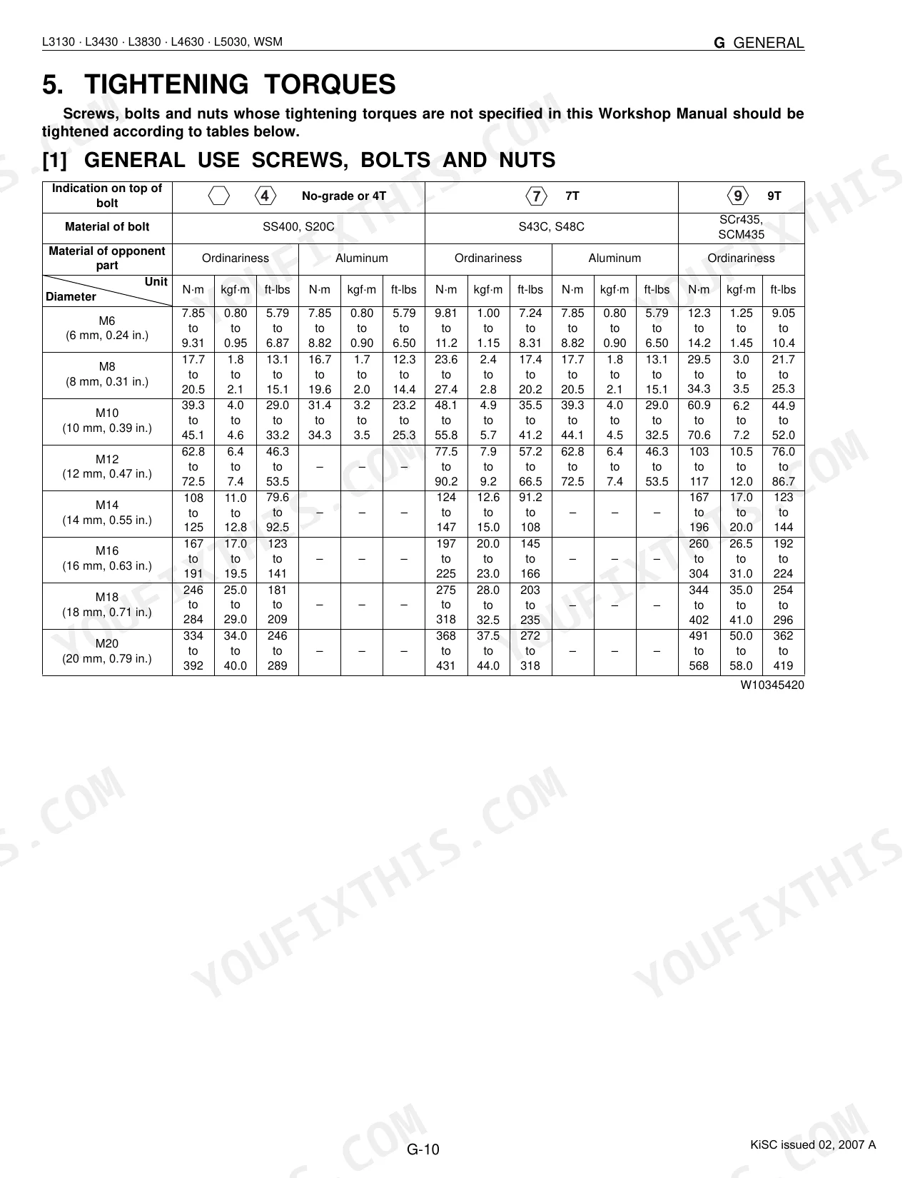
| G General | 19-80 | Tractor, Electrical Parts, Wiring, Battery, Fuse, Connector, Lubricants, Fuel |
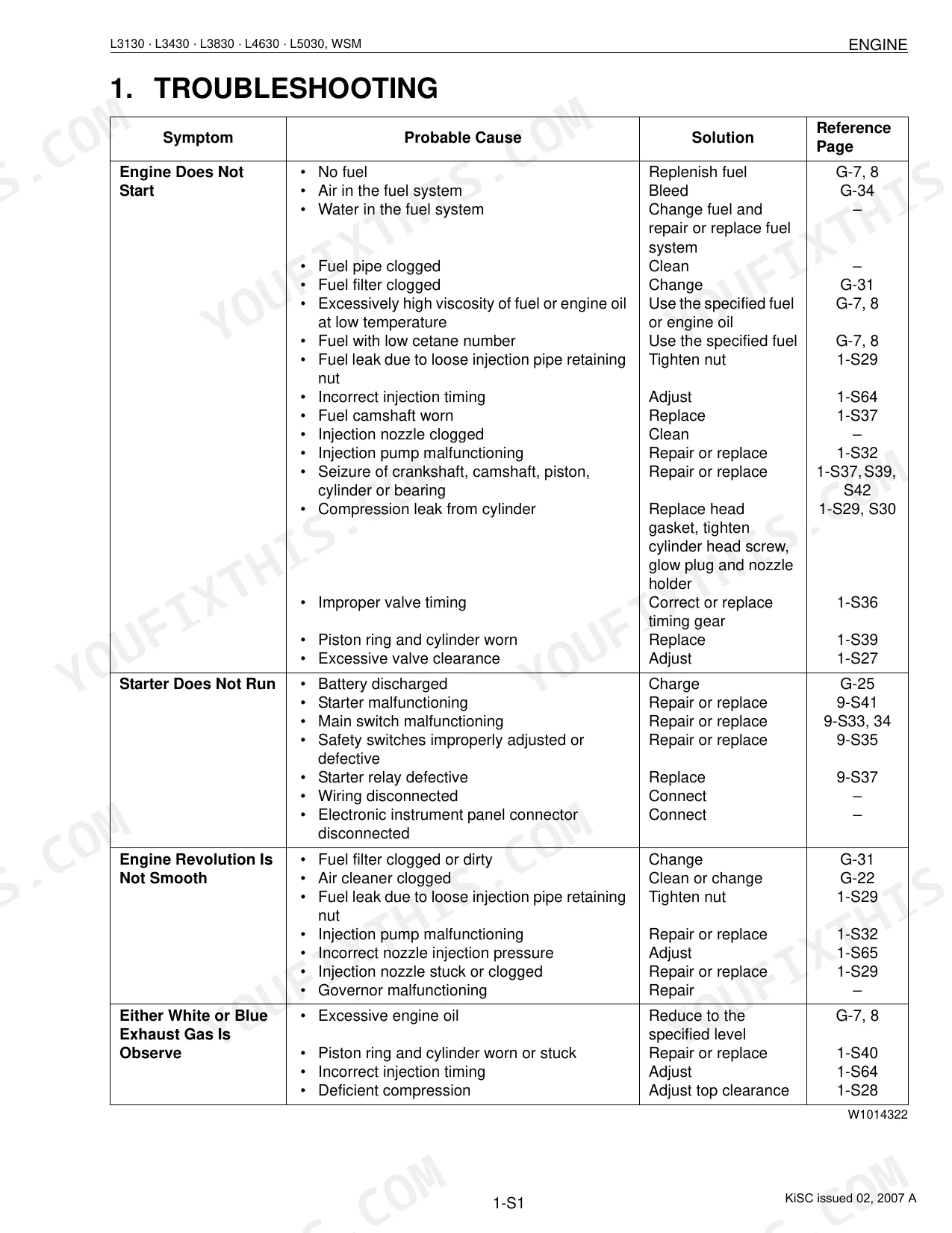
| 1 Engine | 81-152 | Features, Fuel System, Lubricating System, Cooling System |
| 2 Clutch | 153-172 | Clutch Pedal, Clutch Disc, Pressure Plate, Diaphragm Spring, Release Holder, Thrust Ball Bearing |
| 3 Transmission | 173-334 | Main Gear Shift Section, Shuttle Shift Section, Range Gear Shift Section, Front Wheel Drive Section, Creep Gear Shift Section, PTO System |
| 4 Rear Axle | 335-345 | Rear Axle, Rear Axle Case, Differential Gear Shaft, Brake Case, Differential Pinion, Final Gear |
| 5 Brakes | 346-361 | Brake Pedal, Brake Lever Link Shaft, Cam Plate, Brake Disc, Parking Brake Lever |
| 6 Front Axle | 362-386 | Front Axle, Axle Flange, Bevel Gear Case, Spiral Bevel Pinion Shaft, Differential Case, Differential Side Gear |
| 7 Steering | 387-413 | Hydraulic Pump, Steering Controller, Control Valve, Metering Device (Gerotor), Relief Valve, Steering Cylinder |
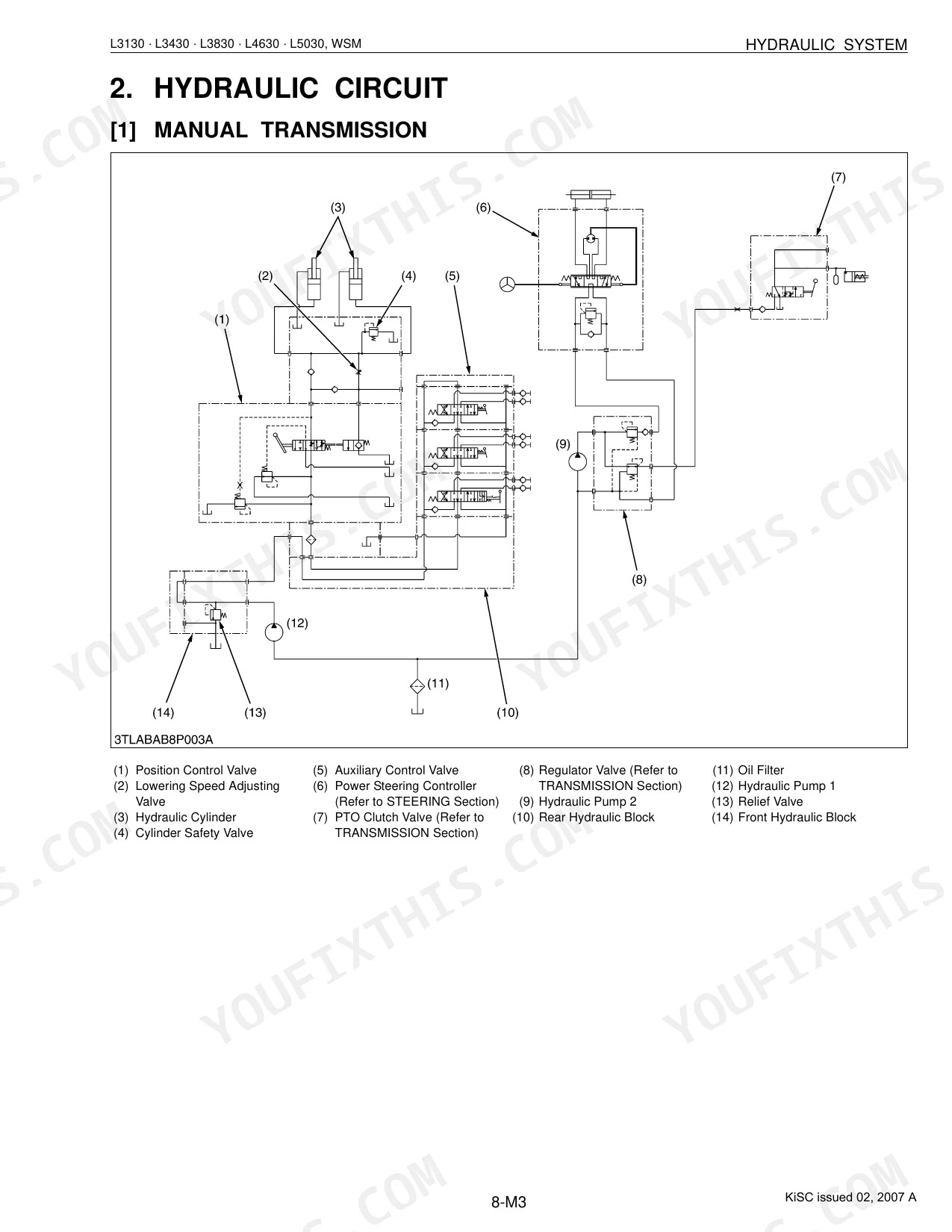
| 8 Hydraulic System | 414-462 | Hydraulic Pump, Front Hydraulic Block, Rear Hydraulic Block, Position Control Valve, Lowering Speed Adjusting Valve, Hydraulic Cylinder |
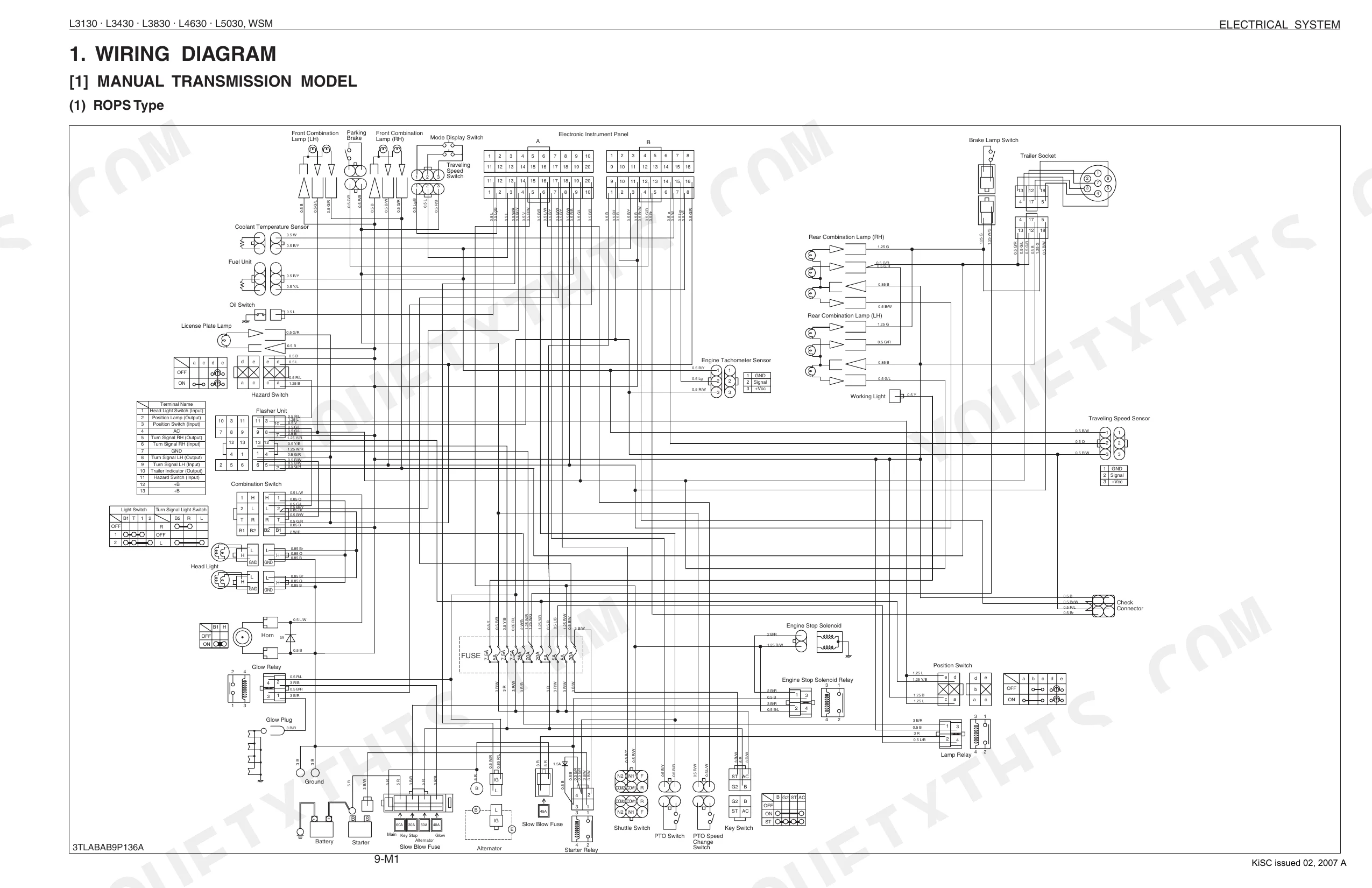
| 9 Electrical System | 463-555 | Wiring Diagram, Electronic Control Panel, Starting System, Charging System, Lighting System, Color of Wiring |
| 10 Cabin | 556-619 | AIR CONDITIONER SYSTEM OUTLINE, SYSTEM CONTROL, ELECTRICAL SYSTEM, A/C Model, Heater Model, Air Conditioner Relay, Blower Relays and Compressor Relay |
Quick Reference Specifications
| Specification | Value | Page |
|---|---|---|
| All Models | ||
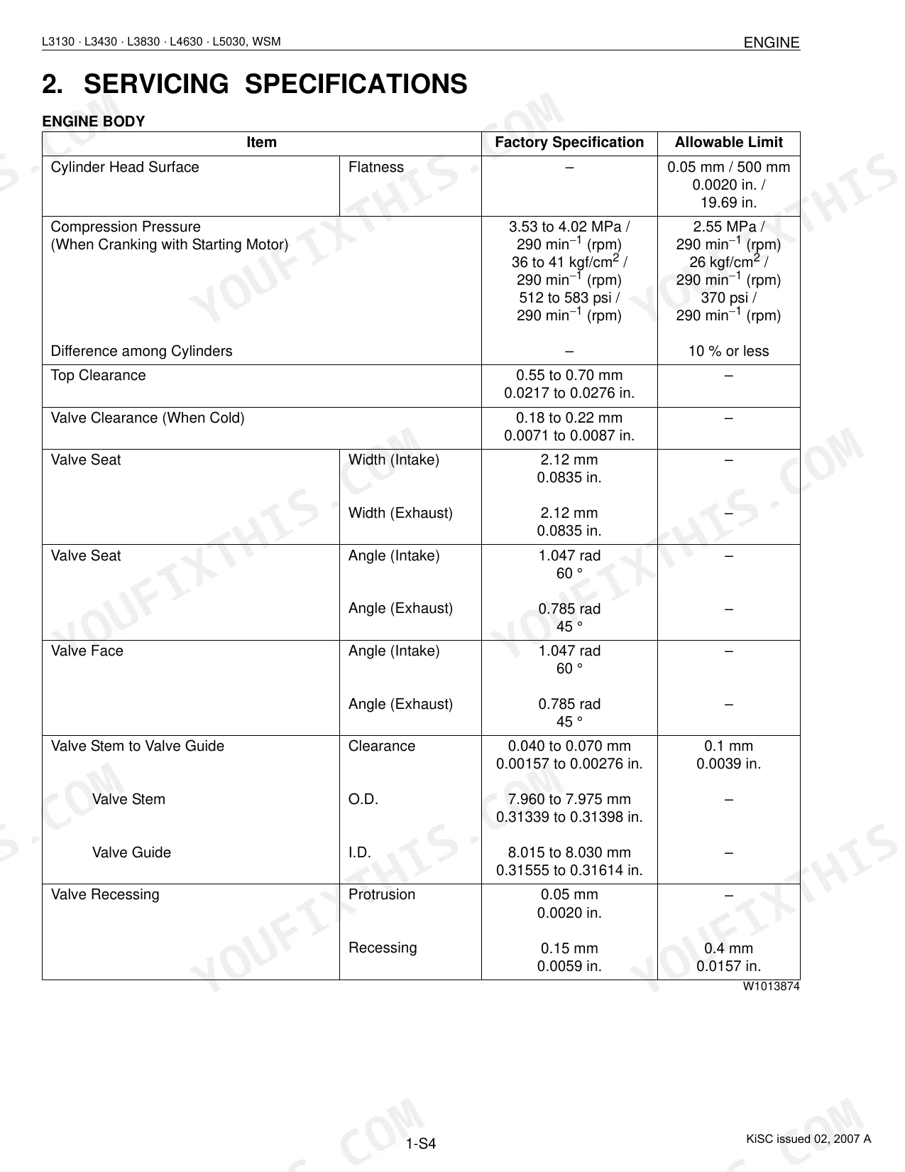
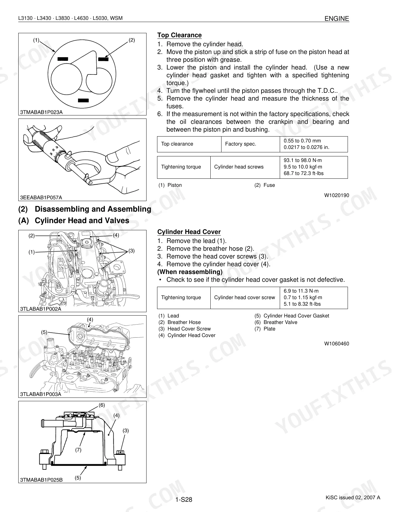
| Cylinder head screws | 93.1 to 98.0 N·m (9.5 to 10.0 kgf·m, 68.7 to 72.3 ft-lbs) | p. 98 |
| Rear wheel mounting screws and nuts | 215 N·m (22 kgf·m, 166 ft-lbs) | p. 41 |
| Hydraulic pump assembly mounting screw and nut | 23.5 to 27.5 N·m (2.4 to 2.8 kgf·m, 17.4 to 20.3 ft-lbs) | p. 444 |
| Alternator pulley nut | 58.3 to 78.9 N·m (5.95 to 8.05 kgf·m, 43.0 to 58.2 ft-lbs) | p. 508 |
| Alternator Stator Resistance | Less than 1.0 Ω | p. 507 |
| Bushing to Gear Shaft Clearance Factory spec. | 0.020 to 0.081 mm (0.0008 to 0.0032 in.) | p. 442 |
| Gear Shaft O.D. Factory spec. | 14.970 to 14.980 mm (0.5894 to 0.5898 in.) | p. 442 |
| Side Plate Thickness Allowable limit | 2.40 mm (0.0945 in.) | p. 442 |
| Battery Terminal Connection Potential difference Reference value | Less than 0.1 V | p. 509 |
| L5030 | ||
| Bevel gear case mounting screw | 166.7 to 196.1 N·m (17.0 to 20.0 kgf·m, 123 to 145 ft-lbs) | p. 370 |
| Fuel tank capacity | 43 L | p. 28 |
| L3130, L3430, L3830, L4630 | ||
| Fuel tank capacity | 40 L | p. 27 |
Kubota L3130–L5030 Series Common Problems This Manual Covers
Kubota L3130 hydraulic pump grinding noise when operating with front end lower than rear for long periods p. 442
Match your serial number against the Kubota service bulletin for this model. Avoid running the tractor with the front axle below the rear for long stretches: engine oil migrates off the pump drive gear and starves the bearing. Measure bushing-to-gear-shaft clearance (factory spec 0.020 to 0.081 mm, page 442) and swap worn parts before returning the machine to service.
Manual Section: 8 Hydraulic SystemCharging warning light stays on, voltage drops, or battery repeatedly goes flat after operating p. 507
Start at the charge wire connector and battery terminals: voltage drop across each connection should stay under 0.1 V (page 509). Pull the alternator and measure brush length (minimum 8.4 mm) and slip ring O.D. (minimum 12.8 mm) against the specs on page 507. Confirm stator resistance below 1.0 Ω and rotor at 2.9 Ω.
Manual Section: 9 Electrical SystemEngine cranks slowly or fails to start, hard white smoke on cold morning starts p. 88
Confirm fuel shut-off and glow plug operation, then work through the no-start troubleshooting chart. Set valve clearance cold to 0.18 to 0.22 mm (page 91). Check that the oil grade suits the ambient temperature and the crankcase sits at the full mark.
Manual Section: 1 EngineRear implement won't lift to maximum height, drops under load, or rises sluggishly p. 403
Inspect hydraulic oil level and condition first. On the L3130, L3430, and L3830, pump delivery must top 18.2 L/min at rated pressure (page 403). Test the lowering speed adjusting valve and position control valve for wear or contamination, and trace each circuit branch on the hydraulic schematic, page 418.
Manual Section: 8 Hydraulic SystemClutch pedal free play out of adjustment, slips under load or drags when disengaged p. 158
Measure clutch pedal free play against the 20 to 30 mm spec (page 158), and adjust the pushrod if it falls outside that range. If slipping continues after adjustment, look at the clutch disc and pressure plate for wear or oil contamination. Verify the release bearing travels smoothly through its full stroke.
Manual Section: 2 ClutchFront wheels wander, pull to one side, or front-wheel drive won't engage p. 368
Set front wheel toe-in with the tractor on level ground to 2 to 8 mm (page 368), adjusting tie-rod length if it reads out of spec. When front-wheel drive won't engage, examine the front axle shift linkage and bevel gear assembly in the front axle section starting on page 362.
Manual Section: 6 Front AxleFrequently Asked Questions
How do I reset the Kubota L3130/L3430/L3830/L4630/L5030 service indicator?
To reset the service indicator lamp, which illuminates every 50 hours, keep pushing both the display mode switch (3) and the travel speed switch (4) for two seconds or more while the hour meter (Normal Display 1) is displayed. This action clears the service alert.
How do I reset the Kubota L3130/L3430/L3830/L4630/L5030 ECU or control module?
Select "Mode D" from the IntelliPanel's mode selection. Wait for "CLEAR" and "PUSH SW" to display, then hold the display mode switch down for more than 2 seconds to delete the error information. Turn off the main switch to end the mode.
What do the Kubota L3130/L3430/L3830/L4630/L5030 error codes mean?
Codes show on the LCD screen: ERROR-00 flags electronic meter trouble, ERROR-10 an HST range gear shift lever sensor failure, ERROR-20 a wrong IntelliPanel setting, ERROR-30 an ECU memory device failure, ERROR-40 an input voltage failure to the lever sensor, ERROR-50 a GST lever sensor failure, and ERROR-60 a proportional reducing valve failure. Page 503 holds the full table of codes, their probable causes, and fixes.
How do I clear a fault code on a Kubota L3130/L3430/L3830/L4630/L5030?
Open the "Error Information Reset Mode (Mode D)" on the IntelliPanel using the steps on page 9-S12. With that mode active, bring up "CLEAR" and "PUSH SW," then hold the display mode switch for more than 2 seconds to erase the error information. Switch off the main switch afterward to leave the mode.
How quickly can I access this Kubota L3130–L5030 Series manual after buying?
A 619-page Shop Manual in searchable PDF, ready the moment your checkout completes. Open it on a computer, tablet, or phone with no shipping wait.
Are there any print restrictions on this Kubota L3130–L5030 Series manual?
Yes, print as many copies as you like. There are no restrictions, and plenty of mechanics print just the section they need to carry to the shop floor.
Are there wiring harness diagrams in this Kubota L3130–L5030 Series manual?
Yes. The manual includes full electrical schematics with wire colors, connector locations, and circuit descriptions.
Document Quality
This is a scanned PDF document with an OCR text layer, allowing you to search and copy text throughout. The text quality is crisp and consistently easy to read on every page. Diagrams and illustrations are a mix of sharp vector-like drawings and clear raster images or photos, with all labels remaining readable. Pages are clean with no noticeable scan artifacts, stains, marks, or skewed content. There are a few blank pages with only section titles, serving as dividers.


Reviews
There are no reviews yet.